
Signal Processing
Index 78
Monostable_multivibrator
Published:2009/7/17 4:15:00 Author:Jessie
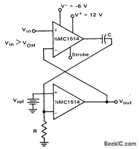
Monostable multivibrator (courtesy Motorola Semiconductor Products Inc.). (View)
View full Circuit Diagram | Comments | Reading(0)
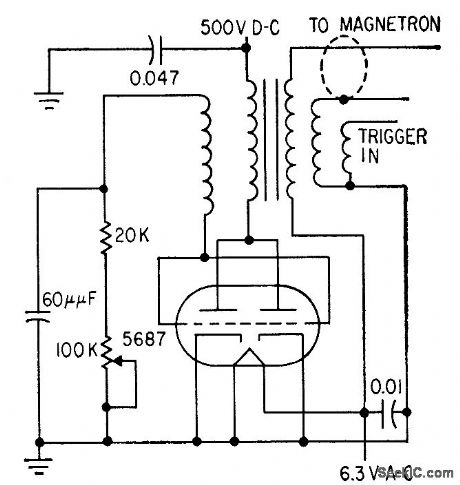
250_KW_MODULATOR
Published:2009/7/17 4:15:00 Author:Jessie
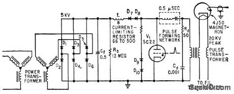
Ten silicon diodes replace five vacuum tubes in artificicd line. type modulator for airborne radar operating at peak power of 250 kw.-M..G. Gray, Using Silicon Diodes in Radar Modulators, Electronics, 32:24, p 70-72. (View)
View full Circuit Diagram | Comments | Reading(778)
NOISE_GENERATOR
Published:2009/7/10 20:55:00 Author:May
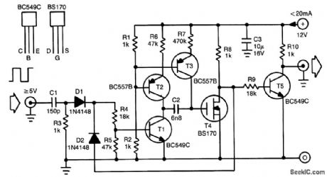
This noise generator provides constant noise energy over its bandwidth, which results from the non-linear behavior of its switching components, more particularly T4. It is very useful for measurements where limited noise bands are required. Varying the ratio R6:R7 and the clock frequency enables the gen-erated noise to be adapted to specific requirements.
Transistors T2 and T3 are current sources. The current through T2 is about 10 times the level of that through T3. Assuming that T4 is on and that the clock input is low, T1 is off, and C2 discharges. The capacitor is pulled to about half of the supply voltage by the two current sources. When that state is reached, stability ensues because the potential then present at the gate of T4 keeps the FET switched on.
When the clock goes high, T1 is switched on so that C2 is connected between the gate of T4 and the earth. Because C2 is only partly charged, the FET is switched off. Transistor T1 is kept switched on by OR gate D1/D2 so that the clock pulses are blocked. Capacitor C2 then charges via T3 until the potential across it becomes high enough to switch on T4. Transistor T1 is then switched off and the circuit is ready to receive another clock pulse (or rather a leading edge of one).
Because it is not known when the clock pulse arrives, it is not known to what potential C2 will be discharged by T2 (and countered by T3). It is therefore also not known when the next clock pulse will arrive. In other words, the pulse width of the output signal is varying constantly, which is characteristic of a noise signal. (View)
View full Circuit Diagram | Comments | Reading(0)
Active_filter_having_a_bandpass_with_60_dB_gain_using_the_ECG925
Published:2009/7/17 5:25:00 Author:Jessie
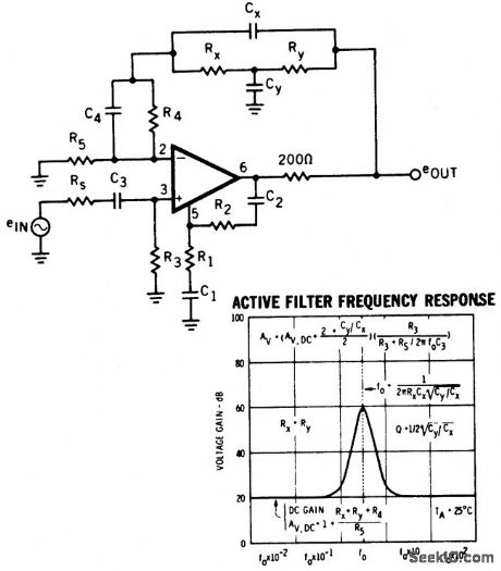
Active filter having a bandpass with 60 dB gain using the ECG925. Typical supply voltage is ±15 volts, but it can be powered with supplies ranging from ±3 volts to ±22 volts. (View)
View full Circuit Diagram | Comments | Reading(815)
BLOCKING_OSCILLATOR_MODULATOR
Published:2009/7/17 5:24:00 Author:Jessie
High permeability of ferrite-core transformer allows use of few coil turns, keeping capacitance at minimum so narrow pulses are produced.-C. D. Hardin and J. Salerno, Miniature X.-Band Radar Has High Resolution, Electronics, 32:5, p 48-51. (View)
View full Circuit Diagram | Comments | Reading(765)
GRAY_SCALE_TEST_GENERATOR
Published:2009/7/10 6:01:00 Author:May

Synchronized LO oscillator drives staircase generator, both of which are reset by horizontal-blanking input signal. Developed for testing video equipment. Synchronized oscillator uses two TTL gates of SN5400, biased at their linear range by negative feedback resistors R1 and R2. Oscillator always starts in same condition. Circuit generates staircase by integrating train of equally spaced pulses Article covers theory and gives design equations.-E. E. Morris, Simple Stair-Step Generator Uses 1IC and 3 Transistors, EDN Magazine, Oct. 1, 1972, p 48-49. (View)
View full Circuit Diagram | Comments | Reading(1362)
STEP_FU_NCTION_GENERATOR
Published:2009/7/10 5:57:00 Author:May
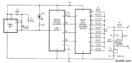
Successively lower resistances at decoder outputs create stairstep function for testing various types of instruments. Steps are equally spaced and of equal height, covering range of 5-12 or 50-120 mV depending on setting of range switch and RS. Spacing between steps ranges from 1.6 s to 6 min, so total time for complete 10-step stair-case is 16 s to 60 min depending on setting of 2.5-megohm timer pot. Reference voltage Vb can be 1.45-V mercury cell. Resistor values shown for Rd provide fixed 10% increments in stairstep.-M. M. Lacefield, Simple Step-Function Generator Aids in Testing Instruments, Electronics, Dec. 26, 1974, p 103 and 105. (View)
View full Circuit Diagram | Comments | Reading(1006)
STEP_GENERATOR
Published:2009/7/10 5:55:00 Author:May
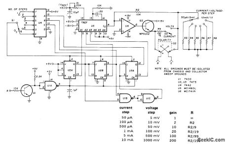
Base-step generator produces series of voltage or current steps synchronized with beginning of each collector voltage sweep, for application to base or gate of three-terminal semiconductor, device while sweep voltage is applied to collector of curve tracer that displays current-voltage characteristics on CRO. Circuit is bulk around Motorola MC1406L 6-bit D/A converter U5. U1 (7400), U2, and U3 (both 7473) form synchronous divide-by-8 counter whose outputs are applied to A1-A3 inputs of US. U6 (MC1741P1) and Q2 form current amplifier. al is general-purpose NPN transistor having DC current gain of about 30. Point A goes to output of full-wave rectifier using two 50-PIV 1-A diodes connected across 26.4-V secondary of transformer. Table gives values for R3 through R8 as ratio of R2 for various gains and steps. Thus, for 500-mV steps (gain of 100), R7 is about 101 ohms. Accuracy depends on values of R2-R9 used. Never apply voltage steps to base of bipolar transistor.-H. Wurzburg, Integrated Circuit Base-Step Generator, Ham Radio, July 1976, p 44-46. (View)
View full Circuit Diagram | Comments | Reading(4569)
AM_BROADCAS_BAND_SIGNAL_GENERATOR
Published:2009/7/10 5:50:00 Author:May
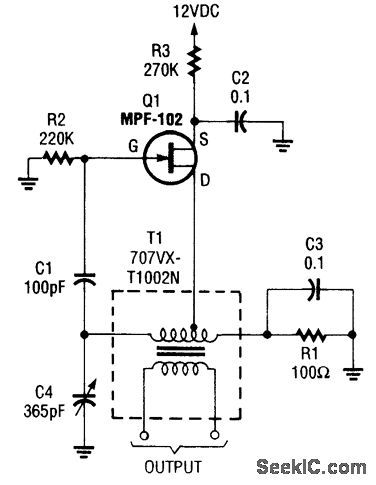
A Hartley oscillator usmg an MPF102 covers the band from 530 to 1600 kHz.T1 is a Toko P/N T1-707VXT1002N 217μhy transformer. (View)
View full Circuit Diagram | Comments | Reading(776)
PULSE_WIDTH_DISCRIMINATOR
Published:2009/7/17 5:09:00 Author:Jessie
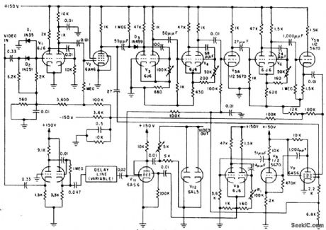
Cuts scanning loss from interfering radars in half, by blanking video signal only if it falls within notch developed by gating circuits. Gives marked improvement in acquisition capability.-K. H. Chase and J. L. Pierzga, Reducing Mutual Radar Interference, Electronics, 32:28, p 39-43. (View)
View full Circuit Diagram | Comments | Reading(1939)
455_kHz_AM_IF_SIGNAL_GENERATOR
Published:2009/7/10 5:36:00 Author:May
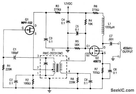
An MPF102 FET oscillator drives a dual-gate MOSFET buffer.The MPF102is configured as aHartley oscillator.If desired,an audio voltage can be coupled to the junction of R4,R5,and CS with anextra coupling capacitor(≈1μF) to AM modulate the signal.T1=Toko P/N RMC-202313NO. (View)
View full Circuit Diagram | Comments | Reading(2838)
BLOCKING_OSCILLATOR_FOR_10_1_SYNC
Published:2009/7/19 21:04:00 Author:Jessie
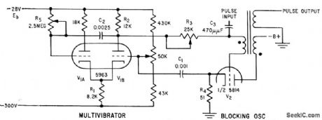
Combines basic mvbr and blocking oscillator into self-gated oscillator that gives synchronization ratio of 10:1 or greater, with stability equal to that of conventional circuit having 1:1 synchronization.-W. W. Whatley Blocking Oscillator for Ten-to-One Sychronization, Electronics, 32:48, p 58-59. (View)
View full Circuit Diagram | Comments | Reading(880)
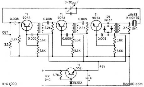
TWO_STAGE_VARIABLE_FREQUENCY_CRYSTAL_OSCILLATOR
Published:2009/7/19 21:03:00 Author:Jessie
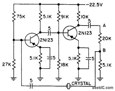
Operates at 9.1 kc with long-term frequency stability of a few parts per million. Frequency can be pulled up to 5 cps off resonance by adjusting trimmer capacitor in series with crystal. Used in analog and digital systems to achieve calibration by deviating carrier frequency a small but accurately known amount.-G. A. Gedney and G. M. Davidson, Crystal Oscillator has Variable Frequency, Electronics, 31:7, p 118-119. (View)
View full Circuit Diagram | Comments | Reading(1050)
STABLE_1_MC_OSCILLATOR
Published:2009/7/19 21:02:00 Author:Jessie
Gives frequency stability of one part in 1 billion per day at normal room temperature, at which a 12-Ib, 45-V battery can furnish crystal oven and circuit power for 72 hours.-J. F. Mercurio, Jr., Stable, Low-Cost One-Mc Oscillator, Electronics, 32:6, p 50-51. (View)
View full Circuit Diagram | Comments | Reading(706)
1_kHz_SQUARE_WAVE_GENERATOR
Published:2009/7/10 4:39:00 Author:May
When the output is high, R3 and R4 are in parallel, and C1 charges via R1 until the current in R2 equals that at the noninverting terminal. This action occurs when C1's voltage rises to 2/3 of the supply voltage. At that point, the circuit switches regeneratively. The output switches low and C1 starts to discharge via R1.Now, R4 is effectively disabled and the current to the noninverting terminal is determined solely by R3, so C1 discharges until the current through R2 falls slightly below that of R3.This happens when the voltage across C1 falls to about 1/3 of the supply voltage. At that point, the circuit again switches regeneratively, and the output again goes high.This circuit is useful for generating symmetrical square waves with maximum frequencies of only a few kHz. Because of the poor slew-rate characteristics of the LM3900 (0.5 V/μs), the output waveforms have rather slow rise and fall times. (View)
View full Circuit Diagram | Comments | Reading(794)
SIMPLE_VARIABLE_FREQUENCY_SQUARE_WAVE_GENERATOR
Published:2009/7/10 4:23:00 Author:May
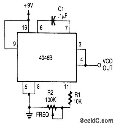
A CD4046B PLL is used as a simple generator.The range is 200 Hz to 2 kHz, but it can be changed by changing C1. (View)
View full Circuit Diagram | Comments | Reading(1658)
4_DECADE_SQUARE_WAVE_GENERATOR
Published:2009/7/10 4:21:00 Author:May
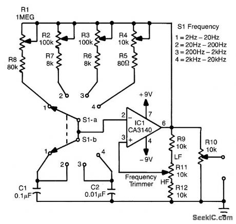
This circuit will generate a square wave of 2 Hz to 20 kHz. The circuit uses an op amp in a relaxation-oscillator configuration. The output is about 15 VPP. R1 through.R4. are calibrols for the four frequency ranges, as selected by S1-a and 51-b. R10 adjusts the output level. (View)
View full Circuit Diagram | Comments | Reading(832)
2000_MC_GENERATOR
Published:2009/7/19 21:42:00 Author:Jessie
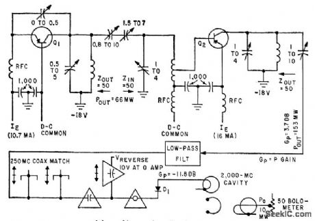
Depends on harmonic frequency conversion. Oscillator Q1 and amplifier Q2 deliver 153 mw at 250 Mc to coaxial matching section. Despite conversion loss of 11.8 db in 8th-harmonic generator D1, output of 10 mw at 2,000 Mc appears across 50-ohm bolometer.-M. M. Fortini and J. Vilms, Solid-State Generator for Microwave Power, Electronics, 32:36, p 42-43. (View)
View full Circuit Diagram | Comments | Reading(891)
FREQUENCY_SHIFT_KEYED_OSCILLATOR
Published:2009/7/19 21:40:00 Author:Jessie
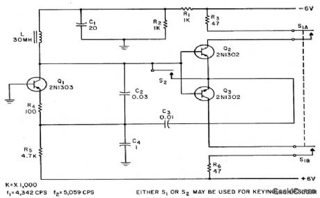
Q1 is Colpitts oscillator at 5 kc and Q2-Q3 is push-pull complementary-emitter amplifier with unity voltage gain. Either switch shorts amplifier, thereby increasing tuning capacitance enough to shift frequency 1 kc.-N. C. Hekimian, Getting Rid of Transients in Frequency-Shift Keying, Electronics, 35:45, p 58-59. (View)
View full Circuit Diagram | Comments | Reading(877)
12_22_Mc_VOLTAGE_CONTROLLED_OSCILLA_TOR
Published:2009/7/19 21:38:00 Author:Jessie
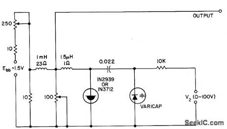
Voltage-variable capacitor tunes tunnel-diode oscillator electronically.- Transistor Manual, Seventh Edition, General Electric Co., 1964, p 350. (View)
View full Circuit Diagram | Comments | Reading(741)
| Pages:78/195 At 206162636465666768697071727374757677787980Under 20 |
Circuit Categories
power supply circuit
Amplifier Circuit
Basic Circuit
LED and Light Circuit
Sensor Circuit
Signal Processing
Electrical Equipment Circuit
Control Circuit
Remote Control Circuit
A/D-D/A Converter Circuit
Audio Circuit
Measuring and Test Circuit
Communication Circuit
Computer-Related Circuit
555 Circuit
Automotive Circuit
Repairing Circuit