
Signal Processing
Index 66
CRYSTAL_CONTROLLED_PRR
Published:2009/7/16 1:22:00 Author:Jessie
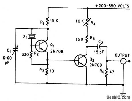
Avalanche pulse generator used with 10.Mc AT.-cut crystal supplies nanosecond pulses with high sea bility and high repetition rate, for phase-locking microwave oscillcators and for generating vhf and uhf local oscillator signals.-J. N. Bridgeman, Crystal Accurately Controls Avalanche Pulse Generator, Electronics, 38:23, p 112-113. (View)
View full Circuit Diagram | Comments | Reading(2398)
AUDIO_DETECTOR_WITH_NOISE_LIMITER
Published:2009/7/16 1:21:00 Author:Jessie
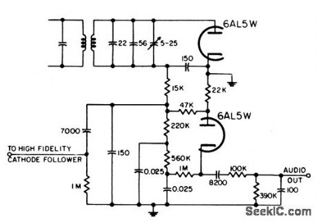
Conventional 6AL5 series noise limiter and diode detector are here augmented by elaborate lone control network.-NBS, Handbook Preferred Circuits Navy Aeronautical Electronic Equipment, Vol. 1, Electron Tube Circuits, 1963, p N12-1. (View)
View full Circuit Diagram | Comments | Reading(1161)
PREFERRED_DETECTOR_AND_NOISE_LIMITER
Published:2009/7/16 1:20:00 Author:Jessie
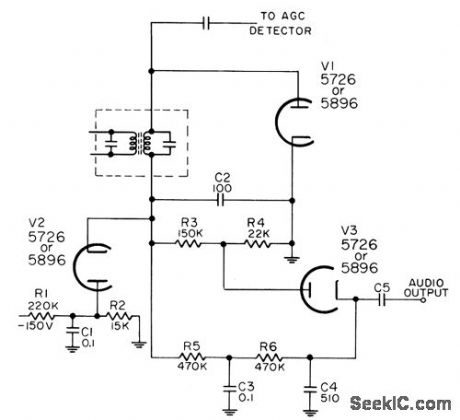
Used in a-m receivers to demodulate i-f output and reduce effect of short-duration electrical disturbances or impulse interference. Audio output is 20 to 150 mv rms, and upper 3-db frequency is 7,000 cps.-NBS, Handbook Preferred Circuits Navy Aeronautical Electronic Equipment, Vol. I, Electron lube Circuits, 1963, PC 62, p 62-2. (View)
View full Circuit Diagram | Comments | Reading(720)
LONG_DUTY_CYCLE
Published:2009/7/16 1:08:00 Author:Jessie
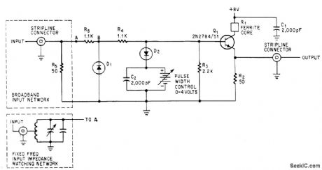
Input shaping network with Inst-recovery diodes permits generation of wide pulses at high repetition rates (up to 100 Mc).-W. T. Rhoades, 100.Mc Pulse Generator Provides 50% Duty Cycle, Electronics, 37:32, p 42-43.
(View)
View full Circuit Diagram | Comments | Reading(824)
PREAMP_COVERS_1_50_MHz
Published:2009/7/16 1:06:00 Author:Jessie
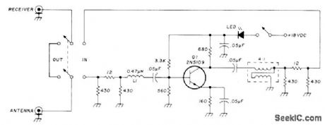
Can be used to improve performance of old communication receivers as well as modern equipment. L1 is several ferrite beads over short loop of about No.20 insulated wire. Transformer is made by winding about 10 bifilar turns of about No. 20 wire on 0.5-inch toroid core. - E. Pacyna, Wideband Preamp, Ham Radio, Oct. 1976, p 60-61. (View)
View full Circuit Diagram | Comments | Reading(776)
WWV_RECEIVER
Published:2009/7/16 1:04:00 Author:Jessie
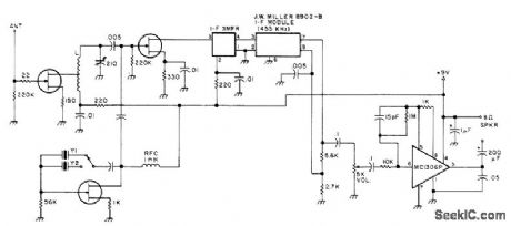
Solid-state components simplify construction of good HF utility-type receiver suitable for monitoring WWV and other station transmissions or for checking specific frequencies in HF bands. Receiver is single-conversion superheterodyne with FET front end, crystal-controlled. No bandswitching is required over 6-15 MHz range. All transistors are MPF 102 or HEP 802. IF transformer is part of Miller IF module. L is 26 turns No.26 on 1/4-inch form, tapped at 13 turns. Y1 is 9.545 MHz for 10-MHz WWV, and Y2 is 14.545 MHz for 15-MHz WWV.-Build a Useful HF Receiver, 73 Magazine, Dec. 1977, p 216-217.
(View)
View full Circuit Diagram | Comments | Reading(6425)
ZERO_CROSSING_PULSES
Published:2009/7/16 1:04:00 Author:Jessie
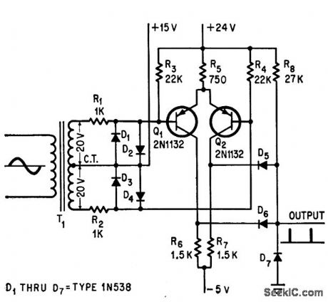
Sharp pulse is pro duced ct each zero crossing, for phase con trol of scr power supply. When instantaneous line voltage is zero, differential amplifier Q1-Q2 is balanced and collectors swing to +2.5 v, causing gate to produce 2-v, 20-microsec output pulse.-S. Prigozy, Zero. Crossing Detector Provides Fast Sync Pulses, Electronics, 38:8 p 91. (View)
View full Circuit Diagram | Comments | Reading(1177)
MONOSTABLE_WITH_ZENER_CLAMP
Published:2009/7/16 1:02:00 Author:Jessie
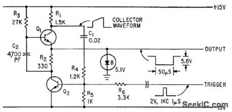
Produces pulses of known length and amplitude when triggered by external pulse.-C. M. Stewart, Monostable Pulse Generator Employs Zener-Diode Clamp, Electronics, 34:19, p 76-77. (View)
View full Circuit Diagram | Comments | Reading(783)
ADJUSTABLE_DUTY_CYCLE
Published:2009/7/16 0:55:00 Author:Jessie
R2 varies off time from 0.25 to 40 sec, while R15 provides variation of over 100 to 1 in ratio of on time to off time. Pulse width and inferpulse time con thus be adjusted independently.-A. A Dargis, On and Off Time Adjusted Independently, Electronics, 37:31, p 50-51.
(View)
View full Circuit Diagram | Comments | Reading(776)
SINE_WAVE_CLIPPER
Published:2009/7/16 0:52:00 Author:Jessie
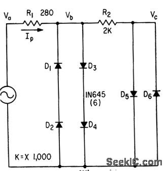
When driven by sine waves circuit gives high-quality square waves over wide frequency range. Output voltage is essentially constant ct 1.5 v peak-to-peak if input voltage is high enough to saturate silicon diodes.-W. E. Nemeth, Two. State Sine-Wave Clipper, Electronics, 34:11, p 64. (View)
View full Circuit Diagram | Comments | Reading(1058)
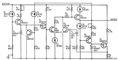
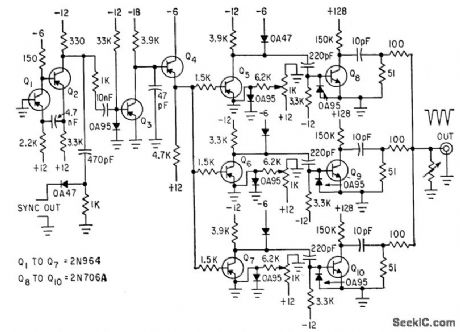
RECTANGULAR_PULSES_GENERATED_IN_PAIRS
Published:2009/7/16 0:50:00 Author:Jessie
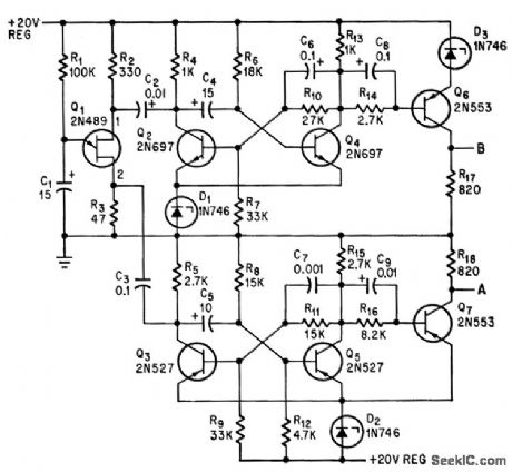
Output A gives 50-millisec positive pulses and output B gives 120-millisec positive pulses, both square wave and both at 0.5 cps, with rise and fall limes under 2 micro. sec for 12.v pulses. Circuit uses one unijunction transistor, two npn transistors, and four pnp transistors.-R. W. Maine, Generating Two Rectangular Waves, Electronics, 37:18, p 82-83. (View)
View full Circuit Diagram | Comments | Reading(714)
VARIABLE_WIDTH_PULSE_GENERATOR
Published:2009/7/16 0:48:00 Author:Jessie

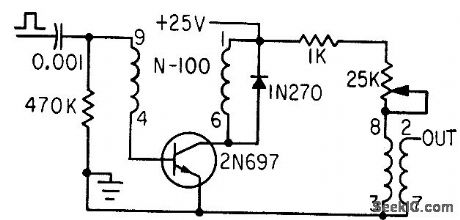
Rheo-stat in series with pulse transformer primary winding controls bitts current to adjust output pulse width over range of 0.06 to 5 microsec. Rise time is less thon 40 nsec.-Blocking Oscillator Has Variable Width Output, Electronics, 36:11, p 156. (View)
View full Circuit Diagram | Comments | Reading(896)
THREE_PULSE_GROUPS_TEST_10_NSEC_DECADE_COUNTERS
Published:2009/7/16 0:19:00 Author:Jessie
Free-running mvbr Q1-Q2 triggers sawtooth generator Q3, which in turn acts through emitter-follower Q4 to drive delay-adjusting amplifiers Q5, Q6 and Q7, each driving silicon tratnsistor working in avalanche mode. Common output is group of three 10-v pulses having rise times below 1 nsec.-R. Charbonnier, Avalanche Transistors Test 10.Nsec Logic, Electronics, 36:28, p 46. (View)
View full Circuit Diagram | Comments | Reading(699)
40_275_MHz_BROADBAND_VMOS
Published:2009/7/16 0:12:00 Author:Jessie
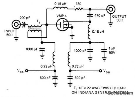
Response is flat within 1 dB over entire frequency range for 12-dB output. Circuit requires no initial adjustments and cannot be damaged by mismatched loads. Designed primarily for communication applications. Uses Siliconix VMP-4 vertical MOS power transistor.-E. Oxner, Will VMOS Power Transistor. - E. Oxner, Will VMOS Power Transistor Replace Bipolars in HF Systems? , EDN Magazine, June 20, 1977, p 71-75. (View)
View full Circuit Diagram | Comments | Reading(757)
TWO-TRANSISTOR_RECEIVER
Published:2009/7/16 0:11:00 Author:Jessie
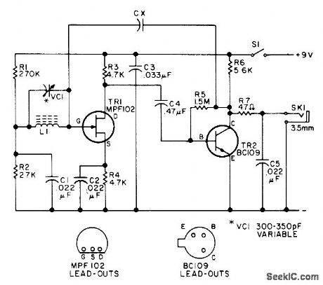
Suitable for reception of local AM broadcast stations, L1 is standard ferrite-rod antenna or suitable winding on 5/16-inch ferrite rod 31/2 inches long, for use with broadcast-band tuning capacitor. Choose value of CX that gives maximum sensitivity.-Circuits, 73 Magazine, July 1975, p 170. (View)
View full Circuit Diagram | Comments | Reading(1972)
2_12_MHz_DIODE_RECEIVER
Published:2009/7/16 0:08:00 Author:Jessie
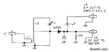
Basic crystal detector circuit can be tuned over 4-MHz range and can also serve as AM detector for 10.7-MHz IF strip. L2 is 64 turns on 1/2-inch diameter air-wound, center-tapped, with 2 turns around it for L1. C1 is about 365 pF. UnmarkedC can be 0.01 μF. - B. Hoisington, Tuned Diode VHF Receivers, 73 Magazine, Dec. 1974, p 81-84. (View)
View full Circuit Diagram | Comments | Reading(992)
AM_HOMODYNE
Published:2009/7/16 0:07:00 Author:Jessie
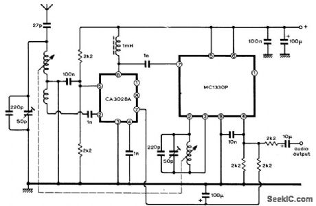
Circuit uses ICs to provide product demodulator that overcomes interstation tuning whistles or heterodynes by deriving local oscillator source from incoming signal carrier. This AM carrier is amplified before modulation is stripped off, and used in homodyne system in which convener output (IF signal) is the same as audio signal. Motorola MC1330P IC, originally developed as color TV video detector, is here connected as synchronous demodulator. RF amplifier IC is RCA CA3028A operating in cascode mode, with permeability tuning of input and RF choke and input of MC1330P together forming output load. Article covers circuit operation in detail and gives alignment procedures. Although developed for broadcast band, basic circuit can be adapted for communication and FM receivers as well.-J. W. Herbert, A Homodyne Receiver, Wireless World, Sept. 1973, p 416-419. (View)
View full Circuit Diagram | Comments | Reading(2976)
100_200_MHz_DIODE_RECEIVER
Published:2009/7/16 0:04:00 Author:Jessie
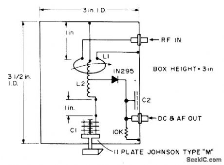
Hybrid tuned-diode version of basic crystal detector uses line cavity cut from sheet copper and soldered into box to give high Q up to 200 MHz. Useful for checking local oscillators around 135 MHz and transmitters around 147 MHz, along with 2-meter transmitters and transceivers. L2 is 4 turns air-wound 1/2 inch diameter and 1/2 inch long, with L1 as 1 turn adjustable around it. C2 is 1 x 2 inch brass plate with 0.005-inch teflon sheet with nylon bolts.-B. Hoisington, Tuned Diode VHF Receivers, 73 Magazine, Dec. 1974, p 81-84. (View)
View full Circuit Diagram | Comments | Reading(962)
RING_TYPE_OSCILLATOR
Published:2009/7/15 23:47:00 Author:Jessie
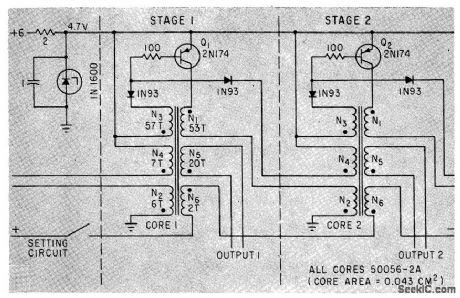
After core-setting current is removed, pulse output of Q1 is followed by output of Q2 after delay of 100 microsec to 3 sec, depending primarily on input voltage and core size. No separate drive oscillator is required when used as ring counter.-J. M. Marzolf, Magnelic-Core Ring Counter Needs No Drive, Electronics, 35:12, p 52-53. (View)
View full Circuit Diagram | Comments | Reading(1082)
WARBLE_TONE_OSCILLATOR
Published:2009/7/13 23:13:00 Author:May
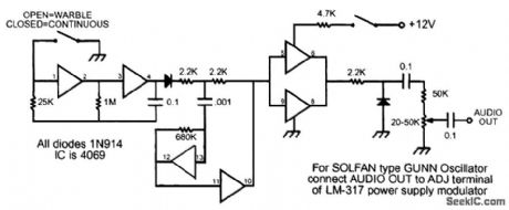
Originally used for microwave transmitter testing, this warble oscillator produces a tone that jumps between two frequencies. (View)
View full Circuit Diagram | Comments | Reading(1267)
| Pages:66/195 At 206162636465666768697071727374757677787980Under 20 |
Circuit Categories
power supply circuit
Amplifier Circuit
Basic Circuit
LED and Light Circuit
Sensor Circuit
Signal Processing
Electrical Equipment Circuit
Control Circuit
Remote Control Circuit
A/D-D/A Converter Circuit
Audio Circuit
Measuring and Test Circuit
Communication Circuit
Computer-Related Circuit
555 Circuit
Automotive Circuit
Repairing Circuit