
Signal Processing
Index 71
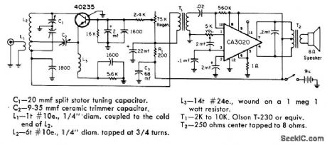
SOS_ON_TWO_FREQUENCIES
Published:2009/7/16 5:22:00 Author:Jessie
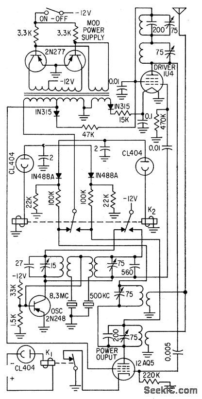
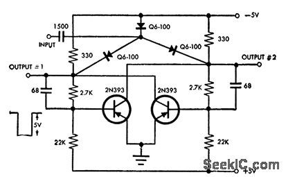
Transistors and tubes are combined for maximum power efficiency at 5-w output. Operates on 500-kc and 8.326.Mc distress frequencies. Code-wheel-operated photoelectric flip-flop automatically switches bands and keys transmitter in SOS code.-H. B. Weisbecker, Distress Transmitter is Hybrid, Electronics, 31:31, p 98-100. (View)
View full Circuit Diagram | Comments | Reading(943)
MICROSEC_FALL_TIME
Published:2009/7/16 5:20:00 Author:Jessie
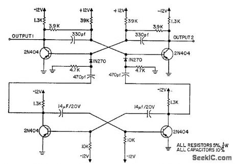
Fast rise time of astable mvbr is used to set and reset bistable flip-flop, whose output waveform follows that of astable with important exception that now both rise and fall limes are very fast, of the order of few microsec for 5-cps square wave.-M. I. Neidich, Astable Multi has Microsecond Fall, EEE, 11:7, p 28. (View)
View full Circuit Diagram | Comments | Reading(920)
BALANCED_PRODUCT_DETECTOR
Published:2009/7/16 5:19:00 Author:Jessie
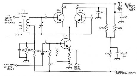
Uses RCA CA3028A differential amplifier U1 to provide conversion gain of about 18 dB for commonly used IF values. Values of tuned circuits depend on frequency used. Unmarked resistors are on IC.-D. DeMaw, Understanding Linear ICs, QST, Feb. 1977, p 19-23. (View)
View full Circuit Diagram | Comments | Reading(1223)
SIX_TRANSISTOFR_AM
Published:2009/7/16 5:11:00 Author:Jessie
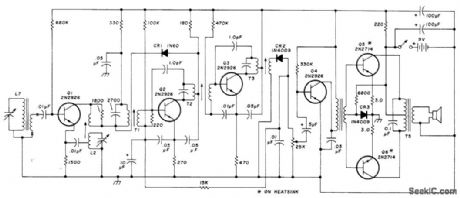
Typical older Magnavox radio uses PNP germanium transistors. L7 is loopstick antenna. Article tens how to add FET converter to radio for use as standard-frequency receiver.-H. Olson, Five-Frequency Receiver for WWV, Ham Radio, July 1976, p 36-38. (View)
View full Circuit Diagram | Comments | Reading(1410)
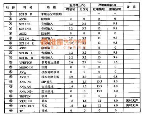
MSP3463G-audio signal processing integrated circuit
Published:2011/7/27 10:07:00 Author:Nancy | Keyword: audio signal
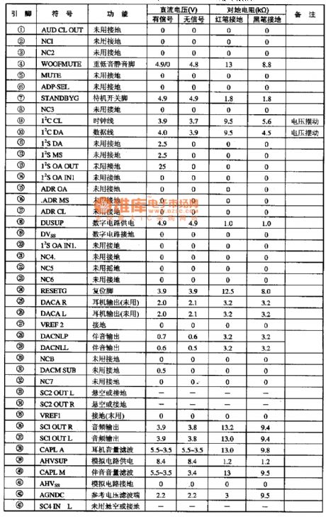
The MSP3463G is a new generation audio signal processing integrated circuit widely used in Konka S series wide screen color TV.
1.Functions and features:The MSP3463G integrated circuit contains I2C bus interface circuit, I2S bus interface circuit, earphone audio amplifier circuit, standby switching circuit, heavy bass mute circuit, and some other auxiliary function circuits. 2. Pin function and data:
The MSP3463G integrated circuit adopts 64 DIP package, which is used in the Konka P2960S, P2971S mirror color TV. The pin function and data is shown as the table. (View)
View full Circuit Diagram | Comments | Reading(744)
VHF_REGENERATIVE
Published:2009/7/16 5:09:00 Author:Jessie
Covers 2-meter amateur band, 152-174 MHz public-service channels including 162.5-MHz weather service, and number of other services. performance is good enough for use as emergency communication receiver. Supply should be six D cells in series; cheaper 9-V transistor radio batteries may have too much impedance and cause motor-boating.-S. Kelly, A Solid State V.H. F. Regenerative Receiver, CQ, March 1970, p 63-64. (View)
View full Circuit Diagram | Comments | Reading(1336)
28_30_MHz_SATELUTE_PREAMP
Published:2009/7/16 5:08:00 Author:Jessie
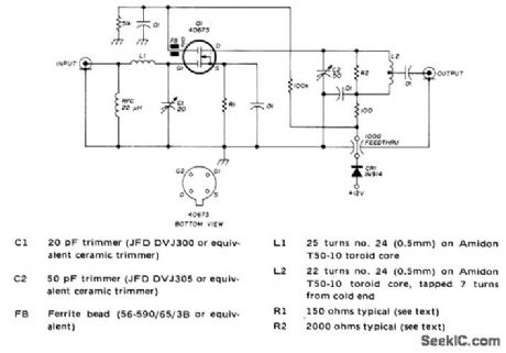
Low-noise design provides up to 25-dB gain and typical noise figure of 1 dB, using dual-gate MOSFET in cascode circuit. Adjust C1 and C2 for maximum output. Developed for use at input of communication receiver. Drain from 12-V power supply should be 3 to 7 mA; if too low or too high, adjust value of R1.-J. Reisert, Jr., Low Noise Figure 28-30 MHz Preamplifier for Satellite Reception, Ham Radio, Oct. 1975, p 48-51. (View)
View full Circuit Diagram | Comments | Reading(1057)
RC_COUPLED_BINARY_STAGE
Published:2009/7/16 5:00:00 Author:Jessie
Typical switching times are 30 and 44 millimicrosec.-Philco MAT Transistors for Logic Circuits up to 5 Mc (Philco ad), Electronics, 33:17, p 50. (View)
View full Circuit Diagram | Comments | Reading(687)
PRODUCT_DETECTOR
Published:2009/7/16 5:00:00 Author:Jessie
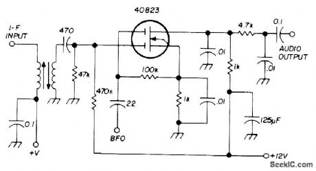
Excellent isolation is provided by dual-gate MOSFET. Used for demodulating SSB or CW signals. Input resonant circuit is tuned to IF value. High-frequency components of signal are filtered out by drain output circuit. RC low-pass filter passes voice frequencies to succeeding audio amplifier.-E. Noll, MOSFET Circuits, Ham Radio, Feb.1975, p50-57. (View)
View full Circuit Diagram | Comments | Reading(0)
2_METER_VMOS_ADDITIVE_MIXER
Published:2009/7/16 4:59:00 Author:Jessie
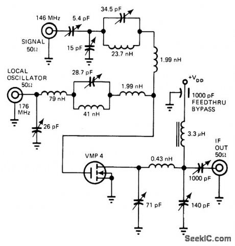
Single-ended circuit for amateur band can deliver 0.5 W of power to IF amplifier while providing conversion gain of 18 dB and compression level of 10 dBm. Noise figure is 5.2 dB. Traps in both signal and noise feeds to Siliconix VMP-4 power transistor prevent radiation of unwanted signals. - E. Oxner, Will VMOS Power Transistors Replace Bipolars in HF Systems ? , EDN Magazine, June 20, 1977, p 71-75. (View)
View full Circuit Diagram | Comments | Reading(858)
14_30_MHz_PRESELECTOR
Published:2009/7/16 4:51:00 Author:Jessie
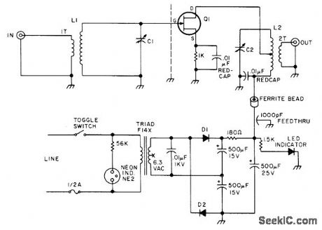
Simple self-powered preselector using FET improves overall noise figure of shortwave receiver along with sensitivity in 14-30 MHz portion of HF band. Also helps reduce cross-modulation from strong out-of-band shortwave broadcast stations. C1 and C2 are 50-500 pF Miller 160B. L1 is 10 turns No. 22 on 750-10 Micrometals core with 1-turn link. L2 is 10 turns No. 22 with center tap and 2-turn link on 750-10 core, Q1 is MPF102, HEP-802, or HEP-F0015. D1 and D2 are 1N4002 or HEP-R0051.-H. Olson, The S38 Is Not Dead!, 73 Magazine, Nov. 1976, p 88-89. (View)
View full Circuit Diagram | Comments | Reading(1670)
3_kV_FOR_CRO
Published:2009/7/13 2:38:00 Author:May
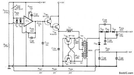
Circuit also provides 1-kV negative supply at 2 mA, as required for cathoderay tube of oscilloscope. Positive supply furnishes 50 μA at 3 kV. Design uses transistor inverter operating at about 20 kHz to simplify filtering. Tr82 and Tr83 form current-switched class D oscillator producing sine waves at high efficiency. Current multiplication is provided by Tr80 and Tr81 for 709 IC opamp.-C.M. Little,A 50 MHz Oscilloscope, Wireless World, July 1975,p 319-322. (View)
View full Circuit Diagram | Comments | Reading(2356)
ALL_BAND_PREAMP_WITH_WHIP
Published:2009/7/16 4:48:00 Author:Jessie

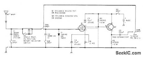
Combination of two-stage preamp and 47-inch telescoping antenna gives overall gain of over 30 dB from 160 to 10 meters, for use with communication and SWL receivers when frequent travel precludes erection of fixed antennas. Use type F, BNC, or SO-239 antenna connector. Tuning coil has 20 taps on 150 turns of No. 28 enamel wire wound on 1/2-inch dowel, with taps at 3, 7, 12, 18, and 25 turns and then about every 10 or 11 turns. Keep leads of at shorted during handling and soldering, to avoid damage by static charges.-K. T. Thurber, Jr., Build A Vacation Special, 73 Magazine, Aug. 1977, p 62-63.
(View)
View full Circuit Diagram | Comments | Reading(1038)
THREE_TONE_VEHICLE_BEACON
Published:2009/7/16 4:46:00 Author:Jessie
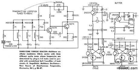
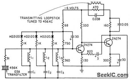
Multitone oscillator modulates 456-kc carrier with three different audio tones whose frequencies are determined by plug-in L-C tanks used in parallel with unstabilized BaTi Transfilter r-f lank circuit.-R. Stapelfeldt, Multitone Oscillcators-New Source of Simultaneous Frequencies, Electronics, 36:1, p 86-87. (View)
View full Circuit Diagram | Comments | Reading(790)
MACHINE_GUN_CONTROL_OSCILLATOR
Published:2009/7/13 2:22:00 Author:May
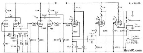
Phase-shift oscillator firing circuit for airborne 20-mm guns permits operation anywhere in range of 600 to 900 rounds per minute,Accuracy is improved by adjusting firing rate away from natural gun-mount vibration frequency.-M. Halio, Firing Circuits Trigger Airborne Machine Guns, Electronics, 31:31, p 86-89. (View)
View full Circuit Diagram | Comments | Reading(1037)
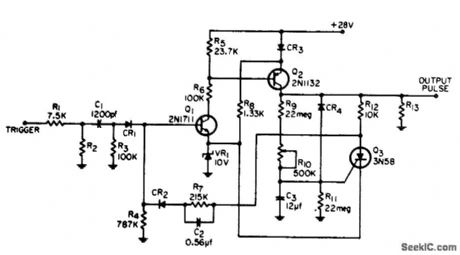
VARIABLE_PULSER
Published:2009/7/16 20:49:00 Author:Jessie
Operates with any power supply voltage from l.5 to 20 v, und generates symmetrical or nonsymmetrical low. impedance pulses from 0.5 ppm to above 200,000 pps. Used for controlling repetitive operation of certain analog computers, and as source for checkout of digital circuits. -J. V. Gaudiosi, Variable Pulse Generator, EEE, 11:2, p 27-28. (View)
View full Circuit Diagram | Comments | Reading(803)
State variable oscillation circuit diagram
Published:2011/8/4 1:53:00 Author:Ecco | Keyword: State variable oscillation
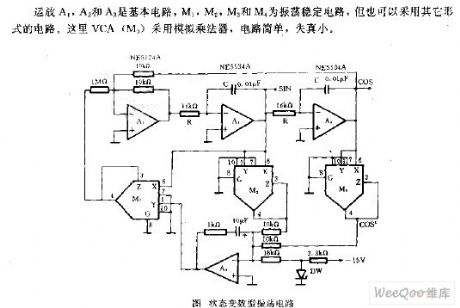
Op amps A1, A2 and A3 are the basic circuits, and M1. , M2, M3 and M4 use the shock stabilizing circuit, but can also use other forms of circuits. The VCA uses the analog multiplier, which is simple with low distortion.
(View)
View full Circuit Diagram | Comments | Reading(1077)
LONG_PULSE_MONO
Published:2009/7/16 12:39:00 Author:Jessie
Advantages are high current gain, long pulse width with relatively small timing capacitance, and low dissipation when off. Pulse width is 11 sec. Drives 19.6K load.-J. M. Meuer, High-Gain, Long-Pulse Monostable, EEE, 14:4, p 41. (View)
View full Circuit Diagram | Comments | Reading(807)
QUARTZ_CRYSTAL_SPECIFICATIONS
Published:2009/7/12 23:49:00 Author:May
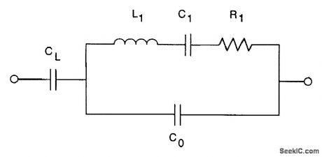


Five main parameters control the characteristics of a crystal, as noted in the equivalent circuit for the figure. These parameters are:
● C1, the motional capacitance● L1, the motional inductance● R1, the equivalent series resistance (ESR)● C0, the parallel capacitance resulting from the electrodes and crystal packaging● CL, external load capacitanbe of the circuit
C1 and L1 are interdependent because they determine the resonant frequency of the crystal. If we know one of the parameters, we can readily compute the other if we know the series resonant frequency. R1 is the resistance determined by the motional (piezoelectric) behavior of the crystal. If it is too high, the crystal might not start oscillation. C0 is a physical capacitor, created by the electrodes plated onto the crystal surface, along with some additional capacitance from the package. Generally, larger C0 contributes to better pullability. CL is the load capacitance of the user's circuit. The crystal must operate at the right frequency in the intended circuit, so this value needs to be included in the crystal purchase specification. (View)
View full Circuit Diagram | Comments | Reading(1303)
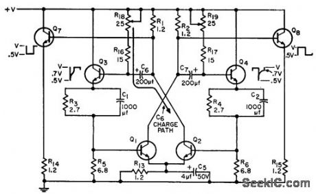
Y_POSITION_DETECTOR_FOR_MISSILE_TRACKER
Published:2009/7/16 11:31:00 Author:Jessie
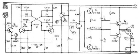
Flip-flop Q2-Q3 is triggered by processed video pulse fed through Q1and by delay vertical sync pulse fed through Q4. Width of flip-flop output pulse, relate to target position is integrated by Q6-Q7 and amplified by Q8-Q9 to give d-c output voltage proportional to Y-position of target. –T. L. Poppelbaum,TV Camera Tracker: Can it Detect Missile Decoys? Electronics, 36:17, p 51-55. (View)
View full Circuit Diagram | Comments | Reading(937)
| Pages:71/195 At 206162636465666768697071727374757677787980Under 20 |
Circuit Categories
power supply circuit
Amplifier Circuit
Basic Circuit
LED and Light Circuit
Sensor Circuit
Signal Processing
Electrical Equipment Circuit
Control Circuit
Remote Control Circuit
A/D-D/A Converter Circuit
Audio Circuit
Measuring and Test Circuit
Communication Circuit
Computer-Related Circuit
555 Circuit
Automotive Circuit
Repairing Circuit