
Signal Processing
Index 74
LOW_POWER_RING_COUNTERLESS_THAN_6_mW
Published:2009/7/16 22:00:00 Author:Jessie
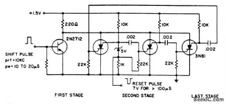
The ring counter operates from 1.0 to 6.0 V and requires only 6 mW at 1.5 V. The reset pulse turns on the first stage with its trailing edge. The maximum shift pulse width increases with voltage and approaches 70 μs for a 6.0-V supply. Minimum pulse width is 10 μs. (View)
View full Circuit Diagram | Comments | Reading(708)
NEGATIVE_PULSE_STRETCHER
Published:2009/7/16 21:59:00 Author:Jessie
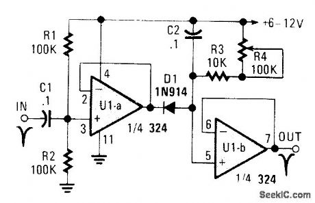
U1A acts as an amplifier, which drives D2 and charges C2. U1B acts as a voltage follower. R3 and R4 determine the amount of stretch that the input pulse receives. C2 can be charged to accommodate different pulse rates. (View)
View full Circuit Diagram | Comments | Reading(749)
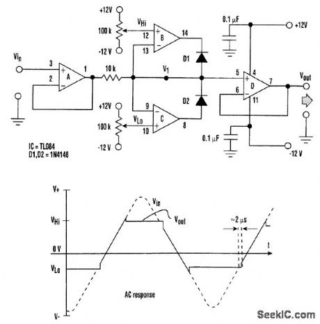
SCHMIDT_TRIGGER_MEMORY_CELL_CIRCUIT
Published:2009/7/16 21:55:00 Author:Jessie
View full Circuit Diagram | Comments | Reading(969)
SHOCK_EXCITED_COSINE_WAVE_OSCILLATOR
Published:2009/7/16 21:53:00 Author:Jessie
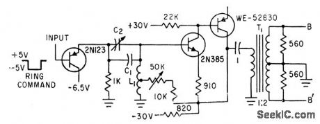
Single 34.1-mlcrosec ring command turns on five identical harmonic generators for alphanumeric character generator.-K. E. Perry and E. J. Aho,Radar-Computer Display Traces Alphanumeric Characters, Electronics, 34:26, p 75-79. (View)
View full Circuit Diagram | Comments | Reading(730)
SHOCK_EXCITED_SINE_WAVE_OSCILLATOR
Published:2009/7/16 21:51:00 Author:Jessie
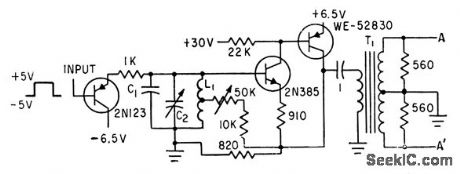
Rectangular pulse turns on five identical harmonic generators for alphanumeric character generator.-K. E. Perry and E. J. Aho, Radar-Computer Display Traces Alphanumeric Charactors, Electronics, 34;26, p 75-19. (View)
View full Circuit Diagram | Comments | Reading(775)
ANALOG_CHARACTER_GENERATOR
Published:2009/7/16 21:49:00 Author:Jessie
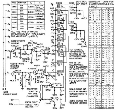
Displays numeric characters 1 through 7 on cathode-ray tube by deflecting spot to trace out each character continuously. X and Y defection voltages are obtained by combining sine and cosine terms of first five harmonics of 30-kc fundamental. Transistorized gated oscillators, flip-flop serial counters, and emitter -followers feed 10 toroidal transformers having one sot of secondary windings for each character.-K. E. Perry and E. J. Aha, Generating Characters for Cathode-Ray Readout, Electronics, 31:1, p 72-75. (View)
View full Circuit Diagram | Comments | Reading(958)
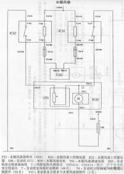
Zhonghua Car AirConditioning System Circuit (the 6th)
Published:2011/7/18 5:06:00 Author:Felicity | Keyword: Zhonghua Car, Air Conditioning System, Circuit
View full Circuit Diagram | Comments | Reading(560)
ZENER_DIODE_SIMULATOR_CIRCUIT
Published:2009/7/16 23:09:00 Author:Jessie
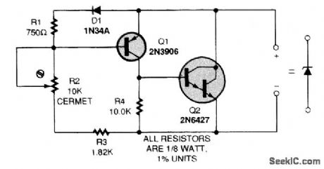
Conventional zener diodes, unless specially compensated, all exhibit a similar problem: As the zener bias current increases, the temperature coefficient also increases in a positive direction. Also, the temperature compensation can be negative or positive, depending on the zener voltage and the particular bias current used-even for a single diode over its characteristic curve! Also, zener diodes available for less than approximately 5.0-V values exhibit very weak knees, where the zener impedance causes a large voltage change over the full bias-current range. This circuit is an attempt to reduce those problems. The bias current range is 1 to 20 mA, and this can be extended by using a higher-power transistor for Q2. This circuit has an adjustable zener voltage of from 1.5 to 6.5 V. That voltage (VZ)can be determined using
VZ=1.5=(5R2/104)
For any setting of R2, the voltage varies less than 1 percent over the 2- to 20-mA bias current. The base-emitter voltage of Q1 provides the reference voltage that is temperature D1, a 1N34A germanium diode. A stable voltage of about 375 mV is then present across R1, and a constant current of 0.5 mA flows through the resistor divider. The net temperature coefficient is complex, but it remains below -2mV/℃ because of the interaction of the diode and transistors. Darlington pair Q2 handles all the bias current, except for the 600 μA needed to bias the reference. (View)
View full Circuit Diagram | Comments | Reading(1672)
EXTENDED_68HC11_RESET_TIMEOUT
Published:2009/7/16 23:32:00 Author:Jessie
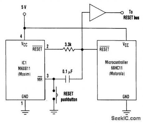
Some microcontrollers (such as the Motorola 68HC11) are implemented with a bidirectional RESET pin that can create a contention problem with the RESET output of certain supervisory ICs. If the supervisor RESET is high, for example, and the microcontroller tries to pull it low, the result might be an intermediate logic level that fails to reset the microcontroller. In addition, some devices on the RESET bus might require a RESET pulse of longer duration than the microcontroller pro-vides. IC1 in the circuit shown eliminates this concern by producing a RESET output with a mini-mum duration of 140 ms. Its RESET output becomes asserted either when the microcontroller initiates a reset, when the MR pushbutton is depressed, or when VCC dips below a threshold internal to IC1. When the reset line is pulled low by IC1 or the microcontroller, MR is pulled low and then re-turns high (initiating a timeout period of 200 ms typical) as the capacitor is charged via the internal MR pull-up resistor. 1C1's RESET deasserts following the timeout, allowing the capacitor to discharge through the internal pull-up resistor and ESD-protection diode. (View)
View full Circuit Diagram | Comments | Reading(1047)
MEASURING_PULSE_LENGTH
Published:2009/7/16 23:23:00 Author:Jessie
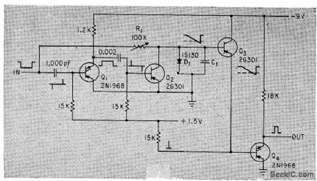
Circuit delivers output pulse only when triggered by input pulse above preset width. Can be used for checking lengths of objects moving past photocell.-K. R. Whittington and G. Robson, Versatile Discriminator Measures Pulse Length, Electronics, 35:31, p 48. (View)
View full Circuit Diagram | Comments | Reading(1008)
Zhonghua Car Air Conditioning System Circuit(the 2nd)
Published:2011/7/18 5:05:00 Author:Felicity | Keyword: Zhonghua Car, Air Conditioning System, Circuit
View full Circuit Diagram | Comments | Reading(695)
Zhonghua Car Air Conditioning System Circuit (the 4th)
Published:2011/7/18 5:05:00 Author:Felicity | Keyword: Zhonghua Car, Air Conditioning System, Circuit
View full Circuit Diagram | Comments | Reading(534)
PHOTOVOLTAIC_ISOLATOR_CIRCUIT
Published:2009/7/16 22:59:00 Author:Jessie
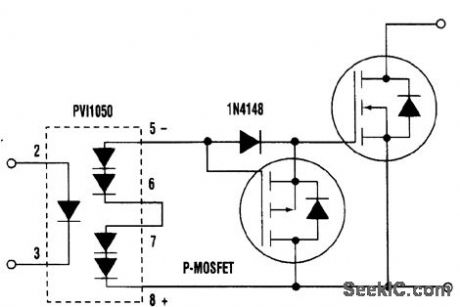
The advantage of the programmable junction transistor (PUT) over a P-MOSFET used as a gate pull-down is that the PUT will pull the gate well below the MOSFET threshold voltage much faster at lower cost. The PUT can discharge a gate capacitance of 5 nF at 12V in 100 ns. (View)
View full Circuit Diagram | Comments | Reading(1251)
ONE_IC_TRANSMIT_TONE_ENCODER
Published:2009/7/16 22:34:00 Author:Jessie
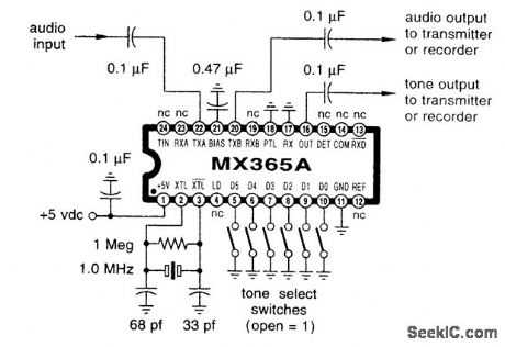
This circuit can be used in a communications transmitter or repeater to place an encoding tone on an audio signal. (View)
View full Circuit Diagram | Comments | Reading(698)
PC_SIGNAL_GENERATOR
Published:2009/7/12 22:20:00 Author:May
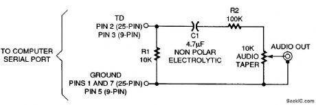
This circuit will produce audio from your PC. The trick is U-the ASCⅡ character U, that is.The hexadecimal value of U is 55, which in binary is 01010101 (with 8 data bits and no parity, or 7 data bits and even parity). The RS232 protocol specifies that the bits of an ASCII character are tran-mitted from least to most significant, preceded by a start bit (always 0) and followed by a stop bit (always 1). So, after adding the requisite start and stop bits, the result is 1010101010. Now, suppose a string of us is generated at the serial port at some steady rate. The result is a continuous series of alternating is and 0s-a square wave. The frequency of the signal will be half the baud rate, which by definition is the number of transitions per second. Each cycle of a square wave comprises two transitions, so, for example, a 9600-bps baud rate produces a 4800-Hz square wave. In practical terms, just about any computer should be able to deliver frequencies of 55, 150, 300, 600, 1200, 2400, and 4800 Hz, corresponding to the standard baud rates from 110 to 9600. The output of a serial port is nominally 24 V p-p, which is much too high a voltage to feed to the input of an audio amplifier. The circuit attenuates the signal to a more useful level, a variable 2-V p-p. The circuit also protects the computer from static electricity and voltage surges. Capacitor C1, a nonpolar unit, blocks dc because the serial port, when idling, outputs approximately -12 V.
(View)
View full Circuit Diagram | Comments | Reading(759)
BAUD_RATE_GENERATOR
Published:2009/7/12 22:07:00 Author:May
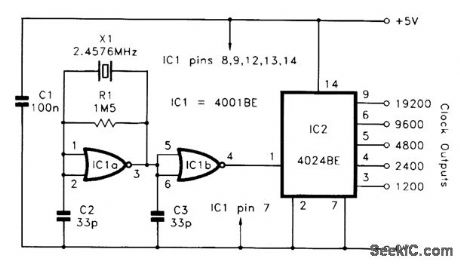
Gate IC1a is used in a conventional crystal oscillator circuit and IC1b acts as a buffer stage. IC2 is a CMOS 4024BE seven-stage binary counter and its clock input is fed with the 2.4576-MHz signal from IC1b. The first two stages of IC2 are not used, but the other five outputs provide baud rates from 1200 to 19,200 baud. Of course, the clock frequency is 16 times the baud rate and output frequencies from IC2 range from 19.2 to 307.2 kHz. (View)
View full Circuit Diagram | Comments | Reading(2389)
MARKER_PULSE_GENERATOR
Published:2009/7/12 21:53:00 Author:May
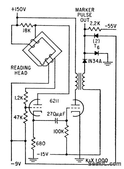
Uses blocking oscillator to generate digit pulses of word being stored in magnetic-spoke disk memory, as well as for generation of index marker pulses.-T.C. Chen and O. B. Stram, Digital Memory System Keeps Circuits Simple,Electronics, 32:11, p130-133. (View)
View full Circuit Diagram | Comments | Reading(1215)
WINDOW_GENERATOR
Published:2009/7/12 21:33:00 Author:May
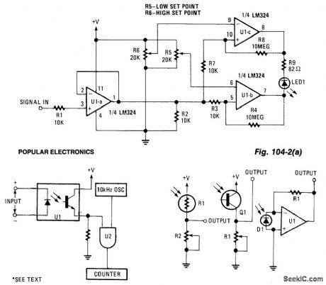
This window generator uses a single LM324 op amp and features two adjustable set points. When the two comparators formed by U1B go high, LED1 lights. When U1C goes high, the LED extinguishes. Some hysteresis is provided by the 10-mΩ resistors. As shown in Fig. 104-2(b), LED1 can be replaced by an optoisolator (etc.) for use in several applications. (View)
View full Circuit Diagram | Comments | Reading(1873)
HARMONIC_GENERATOR
Published:2009/7/12 21:02:00 Author:May
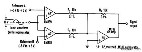
This circuit can extract harmonics from various waveforms. With a sloped input waveform, the comparator produces a pulse width that is proportional to a reference plus input amplitude. As the pulse width changes, the harmonics spectrum changes. Combining the two comparator outputs eliminates some harmonics, depending on the duty cycle. Adjusting the references can create virtually any harmonic.A1 and A2 should be matched, R1 and R2 should be equal to 0.1%, and A3 should have good common-mode rejection and high slew rate. (View)
View full Circuit Diagram | Comments | Reading(0)
CODE_PRACTICE_OSCILLATOR
Published:2009/7/12 20:49:00 Author:May
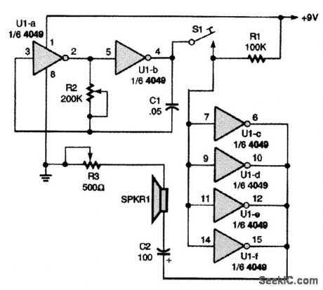
This versatile code-practice oscillator has a variable frequency and volume control. The unit is especially suitable for use by small groups that are interested in learning and practicing code. A single 4049 CMOS hex inverting buffer is the heart of the oscillator, with inverters U1-a and U1-b making up the variable audio-oscillator circuit. The oscillator's output is coupled to the speaker-driver circuit through the CW (Morse code) key S1. The audio frequency of the oscillator (hence, its tone) is varied by the potentiometer. R3 is used to vary the speaker's volume. (View)
View full Circuit Diagram | Comments | Reading(0)
| Pages:74/195 At 206162636465666768697071727374757677787980Under 20 |
Circuit Categories
power supply circuit
Amplifier Circuit
Basic Circuit
LED and Light Circuit
Sensor Circuit
Signal Processing
Electrical Equipment Circuit
Control Circuit
Remote Control Circuit
A/D-D/A Converter Circuit
Audio Circuit
Measuring and Test Circuit
Communication Circuit
Computer-Related Circuit
555 Circuit
Automotive Circuit
Repairing Circuit