
Signal Processing
Index 69
PLL_AS_AM_DEMODULATOR
Published:2009/7/16 2:52:00 Author:Jessie
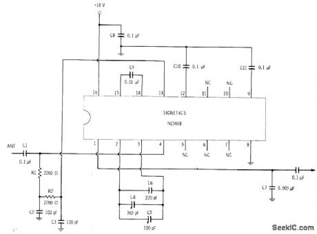
Single phase-locked loop IC provides audio output signal when connected to suitable antenna for broadcast band. Demodulation is achieved without use of input tuned circuits because control oscillator of PLL is locked to frequency of incoming carrier. IC is tuned over broadcast band by changing frequency of internal VCO with external variable capacitor 04. By changing capacitor limits, circuit can be used to cover long-wave and shortwave bands.-E. M. Noll, Linear IC Principles, Experiments, and Projects, Howard W. Sams, Indianapolis, IN, 1974, p 303-305. (View)
View full Circuit Diagram | Comments | Reading(1948)
2_m_LOW_NOISE_PREAMP
Published:2009/7/16 2:51:00 Author:Jessie
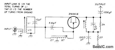
Combination of grounded-gate and grounded-source connections uses bridge arrangement for neutralizing feedback capacitance between gate and drain.Input impedance is transformed in parallel between gate and ground to provide necessary wideband characteristic. Noise figure is between 1 and 2 dB, with gain of about 15 dB. Circuit is unconditionally stable, and combines optimum matching for best noise, lowest input SWR, and high power gain.-U. Rohde, High Dynamic Range Two-Meter Converter, Ham Radio, July 1977, p 55-57. (View)
View full Circuit Diagram | Comments | Reading(847)
SIMPLEST_SWEEP_GENERATOR
Published:2009/7/13 6:09:00 Author:May
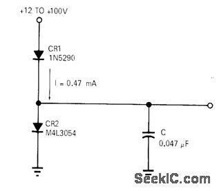
Requires only constant-current generator CR1, Schottky diode CR2, and capacitor. Provides excellent linearity (0.07%) and stability over wide range of supply voltages and temperatures. Sweep rates as high as 100 kHz can be obtained by changing value of C. Article gives design equations.-DR Morgan, Sweep Generator Boasts Only Three Parts, EDN Magazine, Sept. 15, 1970, p 57. (View)
View full Circuit Diagram | Comments | Reading(995)
PLL_DETECTOR
Published:2009/7/16 2:48:00 Author:Jessie
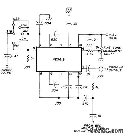
Developed for use with BFO multiplexor in 455-kHz multimode detection system using NE561 phase-locked loop IC. Circuit provides required 90° phase-shift network in series with output of BFO multiplexor, to compensate for lockup of NE561 in quadrature with signal at input of phase detector during AM reception. IF input level to NE561 should be below about 100 mVRMS for minimum distortion. Audio output level will then be at least half that for narrow-band FM, about same for SSB and CW, and about double for AM if both sidebands are passed by IF filters. FM audio output level is proportional to percent deviation and cannot be increased by increasing signal level. Two 0.004-μF capacitors limit audio bandwidth to about 4 kHz. VCO output of NE561 is 0.6 V P-P square wave at AM carrier or BFO frequency.-J. Regula, BFO Multiplexor for a Multimode Detector, Ham Radio, Oct. 1975, p 52-55. (View)
View full Circuit Diagram | Comments | Reading(4146)
EIGHT_PULSE_GENERATOR
Published:2009/7/13 5:43:00 Author:May
With 32-microsec gate following blocking oscillator, produces eight pulses at 4.5-microsec intervals at output of emitter-follower.-W. W. Grannemannet al. Pulse-Height-to-Digital Signal Converter, Electronics, 33:2, p58-60. (View)
View full Circuit Diagram | Comments | Reading(820)
200_MHz_NEUTRALIZED
Published:2009/7/16 2:47:00 Author:Jessie
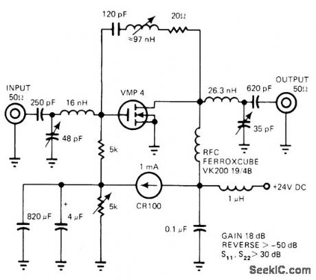
Provides 18.2-dB gain and -50 dB reverse isolation for communication applications. Noise figure is low. Uses Siliconix VMP-4 vertical MOS power transistor.-E. Oxner, Will VMOS Power Transistors Replace Bipolars in HF Systems?. EDN Magazine, June 20, 1977, p 71-75. (View)
View full Circuit Diagram | Comments | Reading(1043)
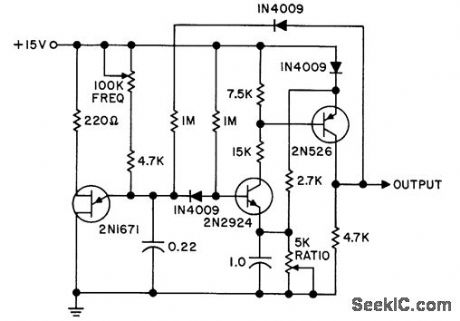
VOLTAGE_CONTROLLED_OSCILLATOR
Published:2009/7/13 5:15:00 Author:May
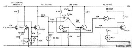
Simple circuit,using feedback to maintain accuracy,converts 0 to 3V d-c linearly to 0 to 400 cps.Uses differential amplifier that amplifies difference between input and feedback signals and feeds frequency-determining output to Shockley four-layer diode oscillator-J. D.Long, Feedback linearizes Voltage-To-Frequency Converter, Electronics, 34:35, p48. (View)
View full Circuit Diagram | Comments | Reading(0)
TRANSDUCER_DRIVEN_CRYSTAL_OSCILLATOR
Published:2009/7/13 5:07:00 Author:May
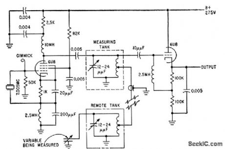
Sensitive 70-Mc one-tube oscillator feeds local and remote tank circuits to which capacitive or inductive transducers may be connetted, for conversion of displacement, temperature, pressure, and other variables to corresponding changes in d-c output voltage.Will give up to 250V change per micromicro-farad of transducer capacitance change.-L. J.Rogers, Sensitive Transducers Use One-Tube Crystal Oscillator, Electronics, 32:40, p48-49. (View)
View full Circuit Diagram | Comments | Reading(1414)
CONSTANT_WIDTH_HIGH_CURRENT_PULSES
Published:2009/7/16 2:37:00 Author:Jessie
Circuit generates negative pulses from -2 to -12 v with rise and fall limes less than 30 nsec. Amplitude and spacing depend on supply voltage. For positive output pulses, use npn transistors and positive supply.- C. P. Hohberger, Fast Pulse Generator Tests Digital Circuit Delay, Electronics, 39:4, p 88-89.
(View)
View full Circuit Diagram | Comments | Reading(696)
SINGLE_PULSE
Published:2009/7/16 2:35:00 Author:Jessie
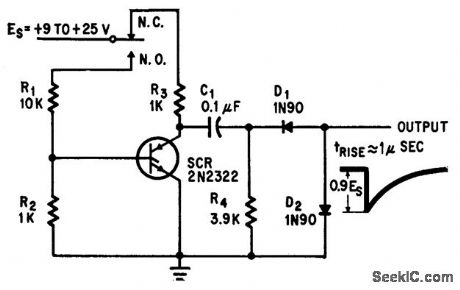
Push button fires scr to produce single pulse with rise time of 1 micro. sec.-R. W. Bailey, Push Button SCR Equals Fast Pulse, Electronics, 37:30, p 41-42. (View)
View full Circuit Diagram | Comments | Reading(932)
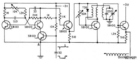
F_M_RECEIVER
Published:2009/7/16 3:41:00 Author:Jessie
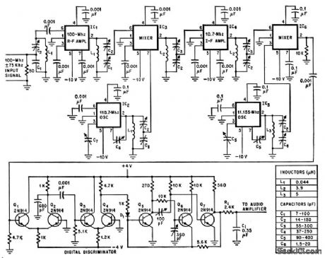
Multipurpose integrated-circuit chip consisting of six resistors and two identical transistors in cascode amplifier con figuration serves three different functions in single-frequency 100-Mc f-m receiver. Although discrete components are used in, digital discriminator, circuit requirements and component values here are compatible with monolithic techniques.-R. L. Sanquini, Multipurpose Chips Cut Costs of F-m Receiver, Electronics, 39:10, p 80-82. (View)
View full Circuit Diagram | Comments | Reading(1138)
9_MHz_CRYSTAL_WITH_MULTIPLIER
Published:2009/7/16 3:40:00 Author:Jessie
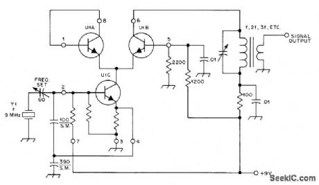
Uses two sections of RCA CA3028A differential amplifier as Colpitts oscillator U1C feeding U1B which can be either amplifier or multiplier depending on values used for output tuned circuit. U1A is not used. Unmarked resistors are on IC.-D. DeMaw, Understanding Linear ICs, QST, Feb. 1977, p 19-23. (View)
View full Circuit Diagram | Comments | Reading(1001)
20_dB_PREAMP_FOR_160_METERS
Published:2009/7/16 3:30:00 Author:Jessie
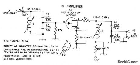
Provides badly needed extra gain when using Beverage or other inefficient low-noise receiving antennas. Gate of common-source JFET is tapped down on tuned circuit by capacitive divider C3-C4 to prevent self-oscillation. Mica compression trimmer C1 provides match to antenna. L1 and L2 are J. W. Miller 43-series slug-tuned coils; L1 has tuning range of 36-57 μH, and L2 has 24-40 μH range. For 160-meter band, L1 and L2 can be peaked at 1827 kHz to provide maximum gain in 1825-1830 kHz DX window.-D. DeMaw, Build This Quickie Preamp, QST, April 1977, p 43-44. (View)
View full Circuit Diagram | Comments | Reading(1625)
VOLTAGE_CONTROLLED_PULSE_SPACING
Published:2009/7/16 4:41:00 Author:Jessie
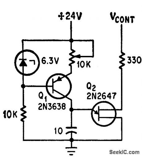
Unijunction transistor circuit generates train of pulses with constant pulse width but with spacing linearly adjustable over 20.to-1 rang by voltage V, which varies trigger point of uit Q2.-A. M. Ridenour and F. Turco, Unijunction Controls Spacing Between Pulses, Electronics, 39:14, p 82-83. (View)
View full Circuit Diagram | Comments | Reading(975)
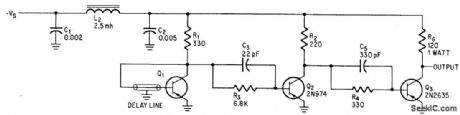
PULSE_CODED_100_WATT_BEACON
Published:2009/7/16 4:41:00 Author:Jessie
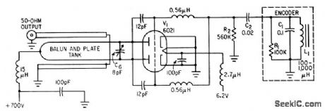
Push-pull power oscillator with transmission-line tank gives good frequency stability at 220 to 260 Mc. Encoder uses capacitor charge and discharge to cut off V1 at intervals giving pairs of 10-microsec pulses to aid in recovery of spacecraft.-J. G. Richter, Redesigning Project Mercury Beacons, Electronics, 35:3, p 50-52. (View)
View full Circuit Diagram | Comments | Reading(823)
PULSE_SQUARING_ZENERS
Published:2009/7/16 4:38:00 Author:Jessie
Addition of zener diodes lo transistor amplifier fed by tunnel.diode pulse generator improves output wave form.-G. B. Smith, Tunnel Diode Generates Rectangular Pulses, Electronics, 33:48, p 124-l25. (View)
View full Circuit Diagram | Comments | Reading(856)
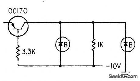
3_LIGHT_SUPERHET_MARKER_BEACON
Published:2009/7/16 4:30:00 Author:Jessie
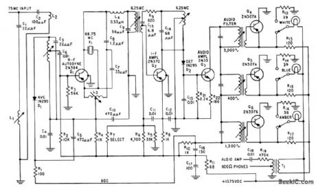
Gives audio output as well as colored-light presentation in aircraft. Superheterodyne provides immunity to spurious activation of lamps by tv stations.-F. P. Smith, Transistorized Receiver for Marker Beacon Use, Electronics, 37:46, p 76-78. (View)
View full Circuit Diagram | Comments | Reading(1398)
LOW_NOISE_RF_INPUT
Published:2009/7/16 4:30:00 Author:Jessie
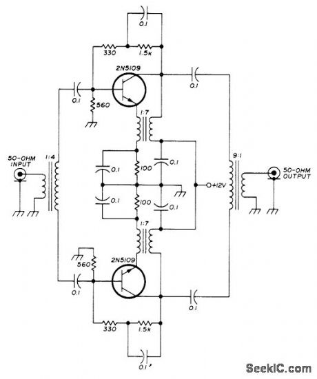
Low-noise version of transistorized push-pull RF stage uses emitter feedback through transformer to give extremely high input and output impedances. Noise figure is below 2 dB. Developed for use in high-quality communication receiver.- U. L. Rohde, Optimum Design for High-Frequency Communications Receivers, Ham Radio, Oct. 1976, p 10-25. (View)
View full Circuit Diagram | Comments | Reading(1264)
MEASURING_MAGNETIC_CHARACTERISTICS
Published:2009/7/16 4:19:00 Author:Jessie
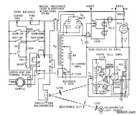
Provides rapid and accurate record of d-c magnetization and hysteresis characteristics of materials.-R. R. Bockemuehl and P. W. Wood, Industrial Hysteresigraph Uses D-c Integration, Electronics, 33:13, p 70-71. (View)
View full Circuit Diagram | Comments | Reading(809)
ELECTRICAL_READOUT_INTEGRATOR
Published:2009/7/16 4:19:00 Author:Jessie
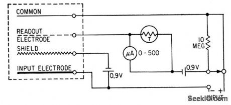
Use of solion diode eliminates need for sensitive electrometer. Integral may be read continuously while integration is taking place, without affecting its value. Varistor is used in parallel with meter to compensate for temperature changes.-R. N. Lane and D. B. Cameron, Current Integration with Solion Liquid Diodes, Electronics, 32:9, p 53-55. (View)
View full Circuit Diagram | Comments | Reading(795)
| Pages:69/195 At 206162636465666768697071727374757677787980Under 20 |
Circuit Categories
power supply circuit
Amplifier Circuit
Basic Circuit
LED and Light Circuit
Sensor Circuit
Signal Processing
Electrical Equipment Circuit
Control Circuit
Remote Control Circuit
A/D-D/A Converter Circuit
Audio Circuit
Measuring and Test Circuit
Communication Circuit
Computer-Related Circuit
555 Circuit
Automotive Circuit
Repairing Circuit