
Control Circuit
Index 131
100_MHz_multifunction_counter_using_the_Intersil_ICM7226A_40_pin_DIP
Published:2009/7/21 21:57:00 Author:Jessie
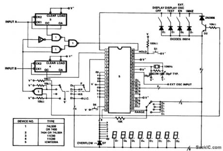
100 MHz multifunction counter using the Intersil ICM7226A 40-pin DIP. This circuit uses a divide-by-10 percaler in the frequency counter mode (courtesy Intersil, Inc.). (View)
View full Circuit Diagram | Comments | Reading(2141)
LIQUID_BATH_THERMOSTAT_FOR_O01°_CONIROL
Published:2009/7/21 21:55:00 Author:Jessie
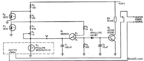
Based on thermistor R2, which has linear temperature coefficient of -6% per degree C from 15 to 35 degree C. R2 is one element in relaxation oscillator also consisting of Q1, C1, R1, R3, and R4.-K. von der Geer, Control is Accurate to 0.01℃, Electronics, 39;12, p 111. (View)
View full Circuit Diagram | Comments | Reading(650)
NULL_INDICATING_DIODE_THERMOMEIER
Published:2009/7/21 21:53:00 Author:Jessie
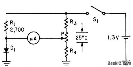
Microammeter serves as null indicator. When potentiometer is adjusted for zero current, arm of potentiometer indicates temperature value directly. Values of R3 and R4 are chosen to place 25℃ range anywhere from near absolute zero to about 40℃.-L. E. Barton, Measuring Temperature with Diodes and Transistors, Electronics, 35:18, p 38-40. (View)
View full Circuit Diagram | Comments | Reading(697)
TEMPERATURE_MONITOR
Published:2009/7/21 21:52:00 Author:Jessie
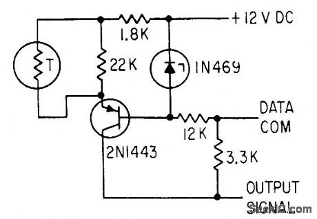
Senses variations in ambient temperature near telemetry detector in space probe. Zener diode maintains constant voltage on transistor base.-S. Chase, Jr. and F. Schwarz, Mariner II Instrumentation:What Will It See on Venus?, EJectronics, 35:50, p 42-45. (View)
View full Circuit Diagram | Comments | Reading(2366)
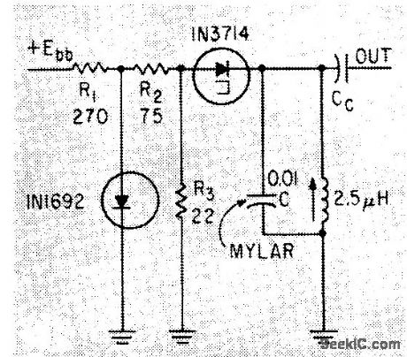
11_Mc_TEMPERATURE_SENSING_OSCILLATOR
Published:2009/7/21 21:41:00 Author:Jessie
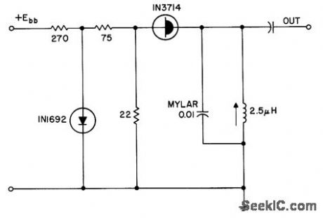
Uses mylar capacitor as main temperature sensing element, with temperature coefficient of 0.5 kc/℃, in tunnel-diode oscillator that translates temperature changes into frequency changes.- Transistor Manual, Seventh Edition, General Electric Co., 1964, p 350. (View)
View full Circuit Diagram | Comments | Reading(690)
4_digit_unit_counter_with_BCD_output_using_an_Intersil_ICM7217A_28_pin_DIP
Published:2009/7/21 21:37:00 Author:Jessie
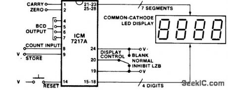
4-digit unit counter with BCD output using an Intersil ICM7217A 28-pin DIP. All that is required is an ICM7217, a power supply and a 4-digit display. Add a momentary switch for reset and an SPDT center-off switch to blank the display or view leading zeros. One more SPDT switch gives you up/down capabilities. With an ICM7217A and a common-cathode calculator-type display this is the least expensive digital counter/display system you can make (courtesy Intersil, Inc.). (View)
View full Circuit Diagram | Comments | Reading(1689)
Clcok_timebase_with_1MHz_reference
Published:2009/7/21 21:52:00 Author:Jessie
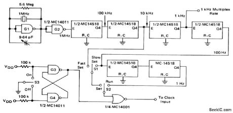
Clcok timebase with 1MHz reference (courtesy Motorola Semiconductor Products Inc.). (View)
View full Circuit Diagram | Comments | Reading(668)
LIMITED_RANGE_DIODE_THERMOMETER
Published:2009/7/21 21:51:00 Author:Jessie
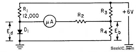
Values of R3 and R4 determine portion of tem perature spectrum to be measured, while R2 determines full-scale temperature value of meter, which may be as low as 25℃. Meter depends on fact that voltage drop across germanium diode is linear function of temperature.-L. E. Barton, Measuring Temperature with Diodes and Transistors, Electronics, 35:18, p 38-40. (View)
View full Circuit Diagram | Comments | Reading(783)
TEMPERATURE_CONTROL
Published:2009/7/21 21:50:00 Author:Jessie
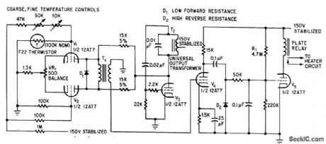
Fast thermal response is obtained with high-resistance thermistor in bridge circuit, feeding chopper V1-V2. V3 is Hartley oscillator operating at about 400 cps, to plate modulate chopper tubes. When bridge is unbalanced by thermister, pulses in secondary ofT1 act through amplifiers V4 and V5 to operate relay. -G. A. R. Trollope, Thermistor Regulator Provides Fast Response, Electronics, 39:5, p 106-107.
(View)
View full Circuit Diagram | Comments | Reading(0)
Time_delay_circuit_with_constant_current_charging_of_timing_circuit_using_a_UJT_and_JFET
Published:2009/7/21 21:48:00 Author:Jessie
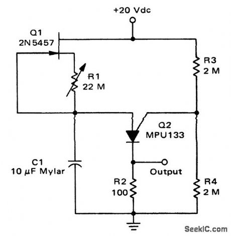
Time delay circuit with constant-current charging of timing circuit using a UJT and JFET. Constant currents of less than 1 μA can easily be obtained that result in time delays up to 10 minutes. (View)
View full Circuit Diagram | Comments | Reading(834)
BATH_TEMPERATURE_CONTROL
Published:2009/7/21 21:48:00 Author:Jessie
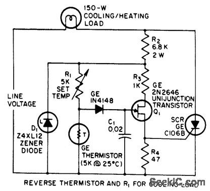
Used to maintain temperature of photographic developer solution constant. When temperature drops, thermistor resistance increases and scr is turned on earlier in each cycle by ujt.-J. Embinder, SCRs in the Consumer Market, EEE, 14:8, p 100-103. (View)
View full Circuit Diagram | Comments | Reading(966)
TEMPERATURE_SENSING_TD_OSCILLATOR
Published:2009/7/21 21:46:00 Author:Jessie
Mylar capacitor with known and reproducible temperature characteristics makes oscillator frequency vary with temperature, Diode bias regulator circuit is used.-E. Gottlieb and J. Giorgis, Tunnel Diodes-Using Them as Sinusoidal Generators, Electronics, 36:24, p 36-42. (View)
View full Circuit Diagram | Comments | Reading(763)
LOW_HYSTERESIS_D_C_LEVEL_DETECTOR
Published:2009/7/21 21:46:00 Author:Jessie
Serves as temperature control when thermistor or other temperature-sensing resistive device is connected to input. Dual complementary transistor Q1 is high-stability d-c amplifier, with zener diode CR1 providing threshold level. With sharp-breaking charatcteristic for zener, hysteresis con be less than 10 mv between turn-on end turn-off. -P. C. Murray, Accurate DC-Level Detector, EEE, 13:12, p 65. (View)
View full Circuit Diagram | Comments | Reading(729)
PROPORTIONING_TEMPERATURE_CONTROL
Published:2009/7/21 21:44:00 Author:Jessie
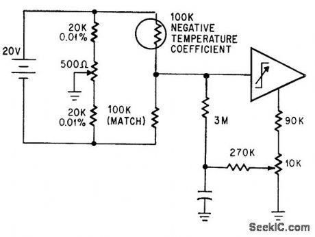
Operational trigger trips when temperature goes beyond 0.001℃ of desired value. Bridge power supply is floating.-P. Lefferts, Operational Trigger For Precise Control, Electronics, 37:28, p 50-55. (View)
View full Circuit Diagram | Comments | Reading(697)
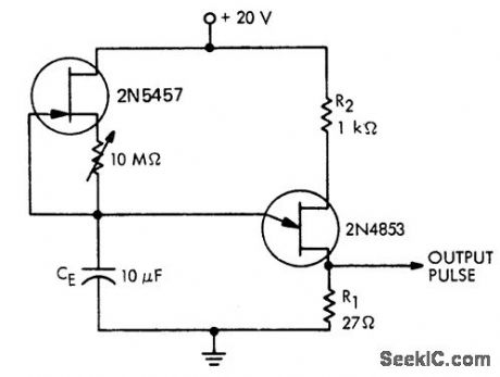
Long_duration_time_delay_circuit
Published:2009/7/21 21:43:00 Author:Jessie
Long duration time delay circuit. Time delays of up to 10 hours are possible with this circuit (courtesy Motorola Semiconductor Products Inc.). (View)
View full Circuit Diagram | Comments | Reading(754)
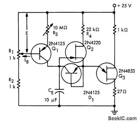
HIGH_ACCURACY_CONTROL
Published:2009/7/21 21:43:00 Author:Jessie
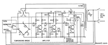
Holds temperature constant to within 0.1℃for any value between -25 and 200℃. For controlling refrigerated unit instead of oven, switch S2 is placed in its other position and output relay is then used to energize solenoid valve that controls fiow of refrigerant.-G. H. P. Kohnke, Electronic Thermostat Controls Temperature to Within 0.1℃,Electronics, 39:1,P 100-102. (View)
View full Circuit Diagram | Comments | Reading(685)
OPAMP_SPEED_CONTROL
Published:2009/7/7 3:16:00 Author:May
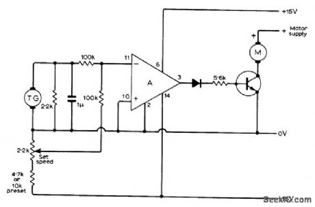
Provides fine speed control of DC motor by using 0.25-W 6-V motor as tachogenerator giving about 4 V at 13,000 rpm. Opamp (RCA 3047A or equivalent) pro-vides switching action for transistor in series with controlled motor, up to within a few volts of supply voltage. Choose transistor to meet motor current requirement.-N. G. Boreham, D.C. Motor Controller, Wireless World, Aug.1971, p 386. (View)
View full Circuit Diagram | Comments | Reading(1628)
WATER_LEVEL_CONTROL
Published:2009/7/7 3:14:00 Author:May
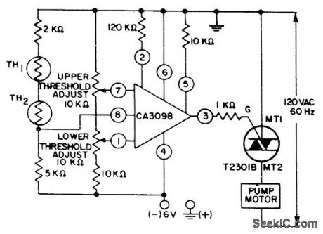
Two thermistors operating in self-heating mode are mounted on sides of water tank. Thermistors change resistance when water level rises so liquid rather than air conducts heat away. Threshold adjustment pots are set so RCA CA3098 programmable Schmitt trigger turns on pump motor when water level rises above thermistor mounted near upper edge of tank, to remove water from tank and prevent overflow. Motor stays on to pump water out of tank until water level drops below location of lower thermistor inside tank.- Linear Integrated Circuit and MOS/ FET's, RCA Solid State Division, Somerville, NJ, 1977, p 218-221. (View)
View full Circuit Diagram | Comments | Reading(2713)
TRIAC_STARTING_SWITCH_FOR_1_2_hp_MOTOR
Published:2009/7/7 3:04:00 Author:May
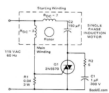
Triac replaces centrifugal switch normally used to control current through starting winding of single-phase induction motor. Value of R1 is chosen so triac turns on only when starting cur-rent exceeds 12A. When motor approaches nor-mal speed, running current drops to 8 A and triac blocks current through starting winding.- Circuit Applications for the Triac, Motorola, Phoenix, AZ, 1971,AN-466, p 8. (View)
View full Circuit Diagram | Comments | Reading(5724)
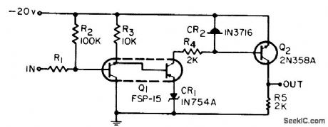
Off_on_control_of_a_triac_with_programmable_hysteresis
Published:2009/7/21 22:13:00 Author:Jessie
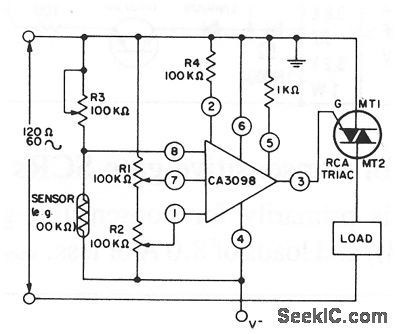
This circuit shows control of a triac with a CA3098 programmable Schmitt trigger. R1 and R7 set the low and high reference voltages, respectively, while R3 sets the control-signal level from the sensor. (View)
View full Circuit Diagram | Comments | Reading(902)
| Pages:131/312 At 20121122123124125126127128129130131132133134135136137138139140Under 20 |
Circuit Categories
power supply circuit
Amplifier Circuit
Basic Circuit
LED and Light Circuit
Sensor Circuit
Signal Processing
Electrical Equipment Circuit
Control Circuit
Remote Control Circuit
A/D-D/A Converter Circuit
Audio Circuit
Measuring and Test Circuit
Communication Circuit
Computer-Related Circuit
555 Circuit
Automotive Circuit
Repairing Circuit