
Control Circuit
Index 135
AC_DC_CONTROL_WITH_SCR
Published:2009/7/6 21:38:00 Author:May
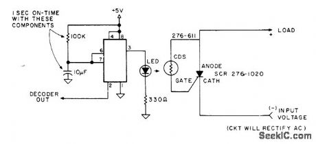
Decoder output of microprocessor feeds 555 timer driving LED that is mounted in light shield with cadmium sulfide photocell. Combination serves as optocoupler for triggering gate of SCR to energize load for short time interval determined by value of resistor and capacitor used. Serves to control small DC motor such as is used to raise or lower transmitter power in small increments.-R. Wright, Utilize ASCII Control Codes!, Kilobaud, Oct. 1977, p 80-83. (View)
View full Circuit Diagram | Comments | Reading(1336)
Crystal_oven_control_circuit
Published:2009/7/22 0:33:00 Author:Jessie
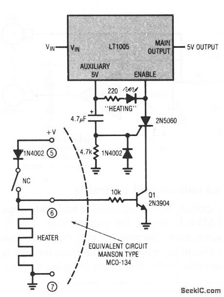
This circuit combines an LT1005 multifunction regulator and a typical commercial crystal oven to prevent equipment use until oven temperature has stabilized (as is often required in precision test equipment). When power is applied, pin 6 of the crystal oven is high, which biases Q1 on. Simultaneously, the SCR gate is triggered by the current flowing through the 4.7-kΩ resistor (the 4.7-μF capacitor charge current). This turns the SCR on and allows the load (the LT1005 enable pin) to receive power. The 4.7-kΩ resistor eliminates false SCR triggering, and the diode suppresses reverse gate current when LT1005 input power is removed. (View)
View full Circuit Diagram | Comments | Reading(878)
LOW_POWER_ZERO_VOLTAGE_SWITCH_TEMPERATURE_CONTROLLER
Published:2009/7/6 21:38:00 Author:May
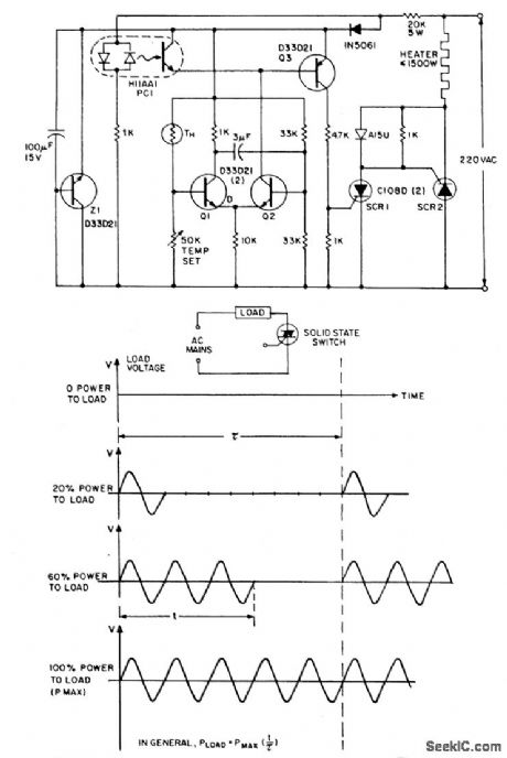


The zero voltage switching technique is widely used to modulate heating and similartypes of ac loads where the time constant associated with the load(tens of seconds tominutes) is sufficiently long to allow smooth proportional modulation by time ratio control,usmg one complete cycle of the ac input voltage as the mlnlmum switching movementoDespite its attractions,the traditional triac-based ZVS is virtually unusable for the controlof very low power loads,especially from 220 volt ac inputs due to the triac's reluctanceto latch-on into the near-zero instantaneous currents that flow through it and the loadnear the ac voltage zero crossover point so The circuit side-steps the latching problem by employing a par of very sensitive low current reverse blocking thyristors(C106)connected in antiparallel;these are triggered by a simple thermistor modulated differential amplifier(Q1,Q2),with zero voltage logic furnished by an H11AA1 ac input optocoupleroWith the NTC thermistor TH calling for heat,transistor Q1 is cut off and Q2 is on,which would normally provide contmuous base drive to Q3,with consequent triggeing of either SCR,or of SCR 2 vla SCR1,depending on phasing of the ac input.Note that when the ac input voltage is positive with respect to SCR 2,SCR 1 isreverse biased and,in the presence of gate current from Q3,behaves as a remotebase transistor, whose output provides vla blocking diode CR1,positive gate triggercurrent for SCR 2.When the ac input polarity is reversed(SCR 1's anode positive),SCR 1 behaves as a direct fired conventional thyristoro Trigger current to SCR 1,however,is not continuous,even when TH is calling for heat and Q2 is delivering basecurrent to Q3.In this situation,Q3 is inhibited from conduction by the clamping actionof POI,an H11AA photocoupler,except during those brief instants when the ac input voltage is near zero and the coupler input diodes are deprived of current.Triggering of either SCR can occur Only at ac voltage crosslng points,and RFI-less operation resultsoThe proportional control feature is injected via the positive feedback action of capacitor CM,which converts the differential amplifier Q1,Q2 into a simple multivibrator,whose duty cycle vanes from one to 99 percent according to the resistance of TH.Zener diode 21 is operational,being preferred when maxlmum immunity from ac voltage induced temperature drift is desired. (View)
View full Circuit Diagram | Comments | Reading(2005)
Overload_protected_motor_speed_controller
Published:2009/7/22 0:26:00 Author:Jessie
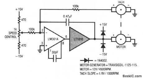
With this circuit, the tach signal is fed back and compared to a reference current, with the LM301A closing the control loop. The 0.47-μF capacitor provides stable compensation. Because the tach output is bipolar, the speed is controllable in both directions, with clean transitions through zero. The LT1010 thermal protection prevents device destruction in the event of mechanical overload or malfunction. (View)
View full Circuit Diagram | Comments | Reading(766)
POLICE_ALERTING_ALARM
Published:2009/7/22 0:03:00 Author:Jessie
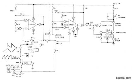
Combination of CA3130 bipolar MOS opamp, CA3094 programmable opamp, and CA3082 transistor array develops large signal swings with various waveforms required for driving loudspeakers to produce attention-getting siren and other sounds. CA3094 is connected as VCO for generating tones that are combined with output of CA3130 astable MVBR to develop required signal swings.- Circuit Ideas for RCA Linear ICs, RCA Solid State Division, Somerville, NJ, 1977, p8. (View)
View full Circuit Diagram | Comments | Reading(1011)
8_BITS_CONTROL_128_BITS
Published:2009/7/6 21:20:00 Author:May
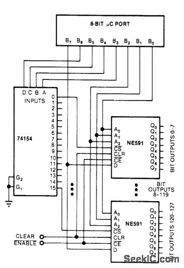
Combination of 74154 demultiplexer and 16 NE591 latches permits control of 128 single-bit outputs with standard 8-bit parallel output of microprocessor. Latches are driven from three low-order bits of microprocessor. Next four higher bits drive 74154 which in turn drives chip-enable inputs of NE591s. Eighth bit of microprocessor drives data inputs of all latches and sets addressed bits appropriately.-R. D. Grappel, Control 128 Bits with an 8-BitμC Port, EDN Magazine, Sept. 5, 1978, p 70 and 72. (View)
View full Circuit Diagram | Comments | Reading(1524)
TWO_TONE_ALARM
Published:2009/7/6 21:07:00 Author:May
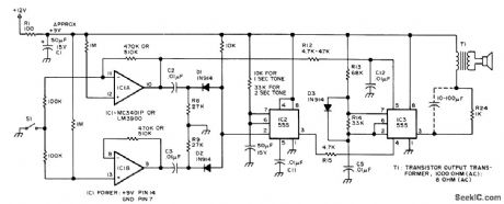
Provides audible backup for visual display in microprocessor-controlled system that requires human intervention under certain conditions, to alert operator who may be watching machinery rather than display. When input line goes high, device emits 1-s beep that means stop. When input goes low, 1-s lower-frequency boop sounds to indicate go. S1 represents signal derived from single-bit computer output. Audio bursts are generated by 555 timers, IC2 is wired as mono MVBR to determine tone duration, set by C4 and R11.Negative-going pulse on pin 2 triggers mono on. ff microprocessor circuit creates pulse rather than level change, input should go to pin 2. Tone frequency is set by C5, R13, and R14 of IC3. Trigger uses IC1A as inverting opamp and IC1B as noninverting opamp. Trigger outputs are differentiated to give negative-going spike for each input level change. Spikes are ORed by Dl and D2 for trigger input of IC2. Different tones are achieved by using IC1A to change input voltage to pin 5 of tone generator IC3. 0p-tional electrolytic capacitor across R24 will in-crease volume.-C. F. Douds, Audible Interrupts for Humans, BYTE, Feb. 1977, p 54 and 58. (View)
View full Circuit Diagram | Comments | Reading(947)
LINEAR_F_M_MODULATOR
Published:2009/7/22 1:17:00 Author:Jessie
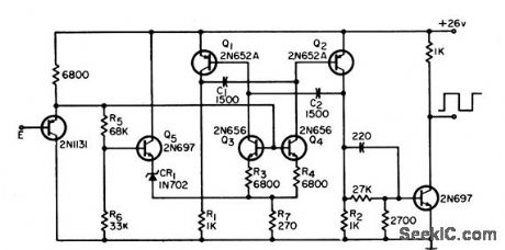
Adding emitter-followers to useable mvbr makes output frequency linear function (within 0.01%) of input voltage for 50% modulation above and below center frequency.-G. Richwell, Linear FM Modulator, EEE, 12:10, p 59-60. (View)
View full Circuit Diagram | Comments | Reading(674)
TEMPERATURE_CONTROL
Published:2009/7/6 21:01:00 Author:May
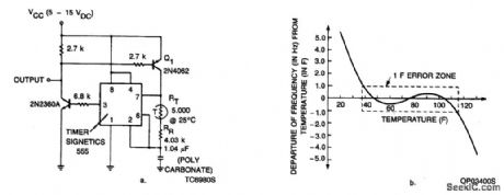
A couple of transistors and a thermistor in the charging network of the 555 type timer enable this device to sense temperature and produce a corresponding frequency output. The circuit is accurate to within ±1 Hz over a 78°F temperature range. (View)
View full Circuit Diagram | Comments | Reading(0)
TEMPERATURE_CONTROLLING_CIRCUIT
Published:2009/7/6 20:59:00 Author:May
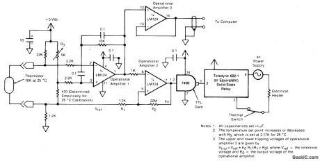
The circuit switches the current to an electrical heater on and off to maintain the temperature of a room at 25 ±0.5℃. The temperature sensor is a thermistor which provides a differential input (for reduced noise) to an operational amplifier. A 5 kilohm potentiometer is used to adjust the set point through a voltage divider; a value of 2.17 kilohms yields the 25℃ setting. A second operational amplifier is connected as an inverting differential-input comparator. The output of operational amplifier 2 controls the electrical heater through a zero-crossing solid-state relay. A transistor/transistor-logic (TTL) gate adjusts the output to the proper level for the relay. A thermal switch is placed in series with the heater and the ac supply for safety in case of thermal runaway. A third operational amplifier monitors the output of the thermistor, providing a signal to a computer for data logging.
(View)
View full Circuit Diagram | Comments | Reading(867)
SCR_RING_COUNTER_DRIVES_HYSTERESIS_MOTOR
Published:2009/7/22 1:28:00 Author:Jessie
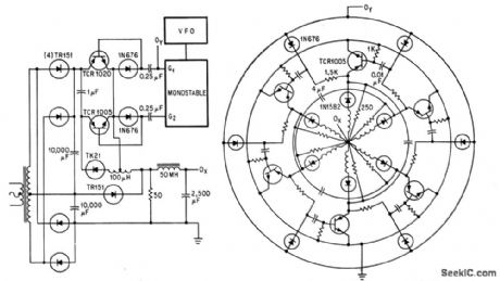
Speed range of 1,200 to 18,000 rpm is obtained with 400-cps, six-pole fractional-hp hysteresis motor by modifying scr ring counter to work in switching mode. Series rectifiers prevent spurious modes during commutation. Output OX of circuit at left goes to centet of circular configuration, and OY goes to outer circle.-R. H. Murphy, Static Alternator Controls Three-Phase Motor, Electronics, 37:15, p 30-33. (View)
View full Circuit Diagram | Comments | Reading(990)
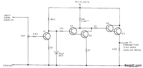
3_W_CLASS_AB
Published:2009/7/22 1:27:00 Author:Jessie
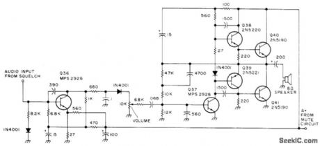
Used in all-band double-conversion super heterodyne receiver for AM, narrow-band FM, CW, and SSB operation. When only noise is present, first audio transistor Q36 is biased out of conduction by squelch and mutes loudspeaker. Supply is 13.6 V regulated. Article gives all circuits of receiver-D. M. Eisenberg, Build This All-Band VHF Receiver, 73 Magazine, Jan, 1975, p 105-112. (View)
View full Circuit Diagram | Comments | Reading(3834)
FULL_WAVE_DRIVE_FOR_D_C_MOTOR
Published:2009/7/22 1:26:00 Author:Jessie
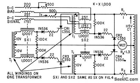
Requires four controlled rectifiers and centertapped transformer. Four magnetic cores ate required for full-wave push-pull action.-W. R. Seegmiller, Controlled Rectifiers Drive A.C and D.C Motors, Electronics, 32:46, p 73-75. (View)
View full Circuit Diagram | Comments | Reading(686)
GONIOMETER_MOTOR_AMPUFIER
Published:2009/7/22 1:24:00 Author:Jessie
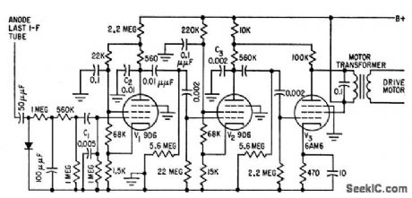
Portion of adf receiver output is separately rectified and applied to selective amplifier V1.V2-V3.C1, C2, and C3 develop 90° phase shift re quired between two coils of goniometer drive motor and serve also as low-pass fiber with sharp cutoff above 150 cps. Overall gain is high enough so motor will exert full torque when goniometer is only 3° off true null.-J. r. Hatch and D. W. G. Byatt, Direction Finder with Automatic Readout Electronics, 32:16, p 62-64. (View)
View full Circuit Diagram | Comments | Reading(1215)
EIGHT_TONE_CRANE_MOTOR_CONTROL
Published:2009/7/22 1:23:00 Author:Jessie
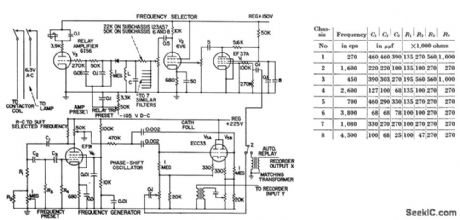
Eight preset frequencies or tones activate collector relays that operate crane motor contactors. Sequence of preselected operations, recorded on magnetic tape, is repeated by traveling crane during playback, to give positioning accuracies better than 1/8th inch. Table gives values of R-C network compo nents in grid circuit of phase-shift oscillator to provide the eight tones.-G. V. Sadler, Taped Tones Control Overhead Crane, Electronics, 31:1, p 63-65. (View)
View full Circuit Diagram | Comments | Reading(3304)
CONSTANT_MOTOR_SPEED
Published:2009/7/22 1:21:00 Author:Jessie
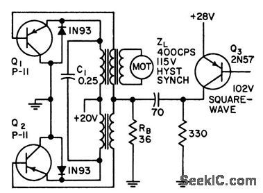
Precise control of instantaneous voltage and current for power transistors gives 90% operating efficiency in driving 400-cps synchronous motor of portable lope transport from 28 v d-c. Negative 800-cps synchronizing pulses from precision oscillator are applied to base of Q3 to pro duce positive pulses at bases of Q1 and Q2, cutting them off quickly.-J. W. Caldwell and T. C. G. Wagner, Boosting Power Transistor Efficiency, Electronics, 31:47, p 86-88. (View)
View full Circuit Diagram | Comments | Reading(714)
FULL_WAVE_CONTROL
Published:2009/7/22 1:20:00 Author:Jessie
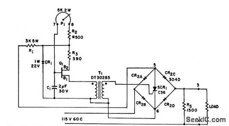
Uses only one control rectifier and one single-ended trigger to obtain continuously variable ac or d-c full-wave output. May be designed for any standard service power voltage. Trigger is always synchronized with power bridge be-cause both obtain power from same source Used to drive and adjust speed of single-phase induction motor, drive and adjust speed of universal motors in machine tools, and vary light output of high-power incandescent lamp.-Full-Wave Control with One Trigger and One Control Rectifier, Electronic Circuit Design Handbook, Mactier Pub Corp., N.Y., 1965, p 187. (View)
View full Circuit Diagram | Comments | Reading(1)
CARRIER_OPERATED_SWITCH
Published:2009/7/22 1:19:00 Author:Jessie
Turns on transmitter of 2-meter FM transceiver (used as repeater) when squelch of receiver is broken by signal. Transmitter remains on about 1s after received signal disappears; for longer delay, use larger electrolytic on collector of Q1. Q1-Q4 can be 2N3904, 2N3565, 2N2222, or other good NPN switching transistor. Q5 is 2N3054 or equivalent, capable of handling 25V at 1 A.-H Cone, The Minirepeater,73 Magazine, June 1975,p55-57,60-62,and 64-65. (View)
View full Circuit Diagram | Comments | Reading(1268)
TRANSFORMER_COUPLED_BASE_MODULATION
Published:2009/7/22 1:19:00 Author:Jessie
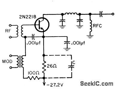
Modulation is in series with r-f signal, so transistor operates in common-emitter con figuration for both r-f and audio. Waveform is good, but modulation power is only 0.7 mw into 900 ohms when audio bypass C is used. Without bypass, modulation power is 1 mw into 200 ohms.-B. Rheinfelder, Modulation Techniques for Transistorized A-M Transmitters, EEE, 11:7, p 54-57. (View)
View full Circuit Diagram | Comments | Reading(832)
SERIES_RESISTOR_PULSE_MODULATOR
Published:2009/7/22 1:18:00 Author:Jessie
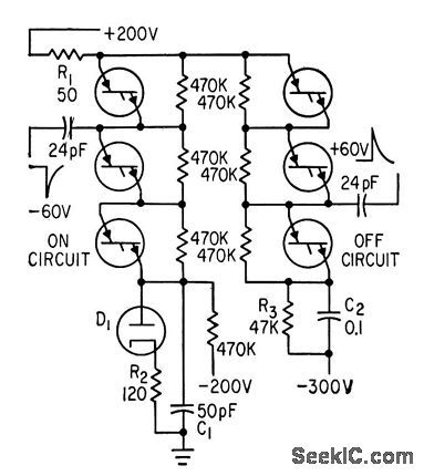
Four, layer diodes with series resistors reduce 350-v,1-cmp pulses to modulate twt and for other applications requiring fast-rise, variable-width, high-current lat-top pulses at repetition rates up to 200 pps.-E. H. Heckman, Three New Approaches to Pulse Modulation, Electronics, 36:18, p 62-64. (View)
View full Circuit Diagram | Comments | Reading(873)
| Pages:135/312 At 20121122123124125126127128129130131132133134135136137138139140Under 20 |
Circuit Categories
power supply circuit
Amplifier Circuit
Basic Circuit
LED and Light Circuit
Sensor Circuit
Signal Processing
Electrical Equipment Circuit
Control Circuit
Remote Control Circuit
A/D-D/A Converter Circuit
Audio Circuit
Measuring and Test Circuit
Communication Circuit
Computer-Related Circuit
555 Circuit
Automotive Circuit
Repairing Circuit