
Control Circuit
Index 140
SOUND_ACTIVATED_SWITCH
Published:2009/7/6 5:52:00 Author:May

The audio from Mia is amplified by Q1. Peaks of signal (adjusted by R1) greater than about 0.7 volts trigger the SCR and light lamp I1. (View)
View full Circuit Diagram | Comments | Reading(0)
VARYING_FREQUENCY_WARNING_ALARM
Published:2009/7/6 5:50:00 Author:May
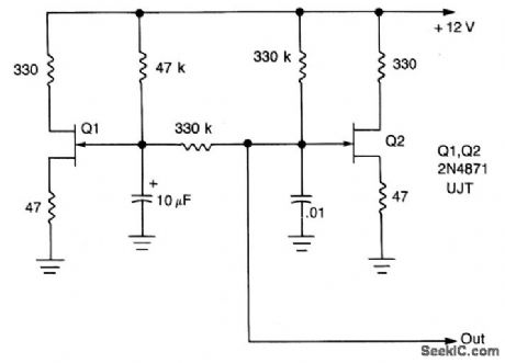
The output frequency changes continuously. Low frequency oscillator (Q1) modulates high frequency oscillator Q2 and its associated timing capacitor.
(View)
View full Circuit Diagram | Comments | Reading(701)
COMMON_MODE_VOLUME_AND_TONE_CONTROL
Published:2009/7/6 5:48:00 Author:May

Eliminates attenuation of signal by conventional voltage-divider type of volume control and gives maximum input impedance. Used with transducers having high source impedance, but will also serve with low-impedance transducers.- Audio Handbook, National Semiconductor, Santa Clara, CA, 1977, p 4-21-4-28. (View)
View full Circuit Diagram | Comments | Reading(792)
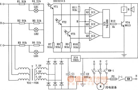
Commercial power safe voltage protector circuit diagram
Published:2011/8/2 2:43:00 Author:Rebekka | Keyword: Commercial power safe voltage protector
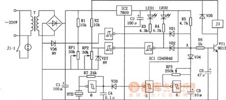
The protector can cut off the power supply automatically and and issue intermittent alarm sound and lighting instructions when the main power protector is lower or higher than the set voltage. The circuit plays the role of automatic protection for household appliances. (View)
View full Circuit Diagram | Comments | Reading(1317)
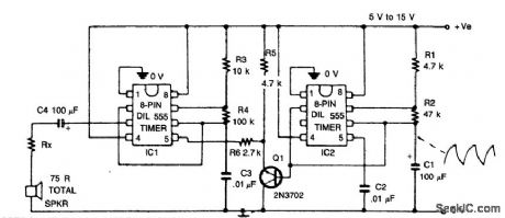
WARBLE_TONE_ALARM
Published:2009/7/6 5:30:00 Author:May
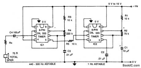
The circuit generates a warble-tone alarm signal that simulates the sound of a British police siren. IC1 is wired as an alarm generator and IC2 is wired as a 1 Hz astable multivibrator. The output of IC2 is used to frequency modulate IC1 via R5. The action is such that the output frequency of IC1 alternates symmetrically between 500 Hz and 440 Hz, taking one sound to complete each alternating cycle. (View)
View full Circuit Diagram | Comments | Reading(1896)
AUTOMATIC_POWER_DOWN_PROTECTION_CIRCUIT
Published:2009/7/6 5:30:00 Author:May
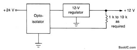
This circuit is faster than a fuse and automatically resets itself when a short is removed. The normal regulated dc input line is opened and the phototransistor of the opto isolator is connected in series with the source and regulator. Between the output of the regulator and ground is a LED and an associated current-limiting resistor, placed physically close to the surface of the photosensitive device. As long as the regulator is delivering its rated output, the LED glows and causes the photo device to have a low resistance. Full current is thus allowed to flow. If a short circuit occurs on the output side of the regulator, the LED goes dark, the resistance of the photo device increases, and the regulator shuts off. When the short is removed, the LED glows, and the regulator resumes operation. (View)
View full Circuit Diagram | Comments | Reading(820)
Voltage photoelectric sensor broken circuit and open phase protection circuit diagram
Published:2011/8/2 2:36:00 Author:Rebekka | Keyword: Voltage photoelectric sensor, broken circuit, open phase protection
The circuit is voltage photoelectric sensor type three-phase broken circuit protector. It will make alarm sound and cut off the power supply automatically. The circuit is shown as above. (View)
View full Circuit Diagram | Comments | Reading(3269)
WAILING_ALARM
Published:2009/7/6 5:28:00 Author:May

This circuit simulates the sound of an American police siren. IC2 is wired as a low frequency astable that has a cycling period of about 6 seconds. The slowly varying ramp waveform on C1 is fed to pnp emitter follower Q1, and is then used to frequency modulate alarm generator IC1 via R6. IC1 has a natural center frequency of about 800Hz. Circuit action is such that the alarm output signal starts at a low frequengy, rises for 3 seconds to a high frequency, then falls over 3 seconds to a low frequency again, and so on ad infinitum.
(View)
View full Circuit Diagram | Comments | Reading(1568)
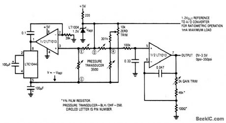
STRAIN_GAUGE_BRIDGE_SIGNAL_CONDITIONER
Published:2009/7/6 4:50:00 Author:May
View full Circuit Diagram | Comments | Reading(687)
HEADLIGHT_ALARM
Published:2009/7/6 3:48:00 Author:May
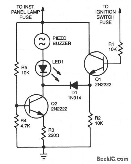
The base of Q1 is connected to the car's ignition circuit. One side of the piezoelectric buzzer is connected to the instrument-panel light fuse. When the headlights are off, no current reaches the buzzer, and therefore nothing happens. What happens when the headlights are on depends on the state of the ignition switch. When the ignition switch is on, transistors Q1 and Q2 are biased on, removing the buzzer and the LED from the circuit.When the ignition switch is turned off, but the headlight switch remains on; transistor Q1 is turned off, but transistor Q2 continues to be biased on. The result is that the voltage is sufficient to sound the buzzer loudly and light the LED. Turning off the headlight switch will end the commotion quickly. (View)
View full Circuit Diagram | Comments | Reading(0)
TRIAC_RELAY_CONTACT_PROTECTION
Published:2009/7/6 3:19:00 Author:May
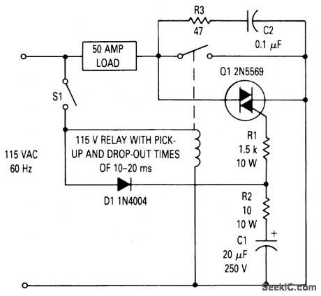
Circuit Notes
This circuit can be used to prevent relay contact arcing for loads up to 50 amperes.There is some delay between the time a relay coil is energized and the time the contacts close. There is also a delay between the time the coil is de-energized and the time the contacts open. For the relay used in this circuit both times are about 15 ms. The TRIAC across the relay contacts will turn on as soon as sufficient gate current is present to fire it. This occurs after switch S1 is closed but before the relay contacts close. When the contacts close, the load current passes through them, rather than through the TRIAC, even though the TRIAC is receiving gate current. If 51 should be closed during the negative half cycle of the ac line, the TRIAC will not turn on immediately but will wait until the voltage begins to go positive, at which time diode Dl conducts providing gate current through R1. The maximum time that could elapse before the TRIAC turns on is 8-1/3 ms for the 60 Hz supply. This is adequate to ensure that the TRIAC will be on before the relay contact closes. (View)
View full Circuit Diagram | Comments | Reading(1367)
TWO_PHASE_VOLTAGE_CONTROLLED
Published:2009/7/6 3:09:00 Author:May

Produces fixed-amplitude sawtooth outputs that can be shaped to give sine waves, with outputs of the two identical channels differing by a specified phase such as 90o. Each output is integrated to give rising or falling ramp that controls switching FET of opposite channel. With oscillation established, one integrator output goes toward zero and the other away from zero, with same or opposite polarity. When first output crosses zero, discriminator switches FET in input amplifier of other channel, witch action being self-perpetuating to give desired sawtooth outputs. Dashed-line gating at outputs of discriminators can be used to boost slope of one sawtooth in one quadrant.-F. B. Jones, Voltage-Controlled Two-Phase Sawtooth Oscillator, Wireless World, June 1973, p 285. (View)
View full Circuit Diagram | Comments | Reading(714)
COURTESY_LIGHT_DELAY_SWITCH
Published:2009/7/6 2:15:00 Author:May
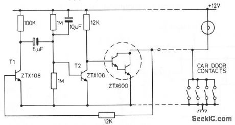

This circuit holds on the internal light for approximately one minute after the car doors are closed. When the door contacts open, a + VE pulse is applied to the base of T1. This transistor turns on, turning off T2 and charging the 10-μF capacitor. T3 turns on, holding on the intemal light . The capacitor takes one minute to discharge when the circuit reverts to its original state. (View)
View full Circuit Diagram | Comments | Reading(819)
5_V_AT_5_A_WITH_IC_SWITCHER
Published:2009/7/6 2:12:00 Author:May
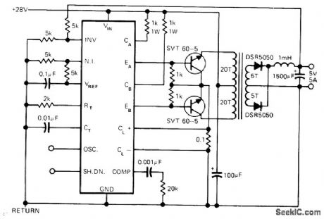
Uses Silicon General SG1524 IC as pulse-width-modulated regulator for which operating frequency remains constant, with ON time of each pulse adjusted to maintain desired output voltage. Operating range extends above 100 kHz but device draws only 10 mA. IC includes voltage reference, oscillator, comparator, error amplifier, current limher, pulse-steering flip-flop, and automatic shutdown for overload.-P. Franson, Today's Monolithic Switching Circuits Greatly Simplify Power-Supply Designs, EDN Maga-zine, March 20, 1977, p 47-48, 51, and 53. (View)
View full Circuit Diagram | Comments | Reading(2147)
PRESET_FREQUENCY_ALARM
Published:2009/7/6 1:35:00 Author:May
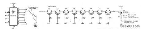
When selected frequency occurs in Nixie-driving counter, alarm circuit triggers and locks until reset manually. Requires one SN7441 Nixie decoder/driver, one decimal-type thumbwheel switch, and one 2N3905 transistor for each digit of display in counter. Four connections are made to each counter stage to get BCD inputs A, B, C, and D for 7441. Connections can be made to 7475 quad latch in typical counter. Circuits are for 8-digit display. When display reaches digit to which switch is set, switch output is grounded. When all switch outputs are grounded, all transistors are turned on and SOP fires to actuate alarm relay. If latching is unclesirable, use medium-power NPN transistor in place of SCR.-W. L. MacDowell, Frequency Detector for Your Counter, 73 Magazine, Oct.1976 p 50-51. (View)
View full Circuit Diagram | Comments | Reading(1047)
DIGITAL_CONTROL_OF_PHASE_ANGLE
Published:2009/7/6 1:16:00 Author:May
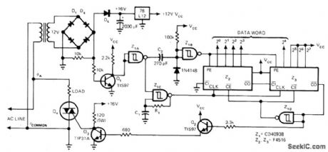
Circuit transforms 5-bit digital control word into phase angle over full range. Resolution is proportional to length of control word. Developed for stage lighting control. Z1C serves as clock oscillator that is periodically synchronized with zero crossings of AC line; R1 and C1 set clock frequency, which for 5-bit control word must be 64 times line frequency or 3.84 kHz. Load requirements determine choice of triac for Q4. Required signal for generating triac drive is produced by D1-D4 and Q1.-R. Tenny, Circuit Provides Digital Phase Control of AC Loads, EDN Magazine. Oct. 5, 1977, p 99-101. (View)
View full Circuit Diagram | Comments | Reading(2502)
Basic_function_tests
Published:2009/7/23 21:43:00 Author:Jessie
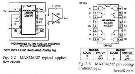
Figures 2-C and 2-D show the typical application circuit and pin configuration/ logic, respectively, for the MAX326/27. Test this ultra-low-leakage CMOS analog switch by applying and removing +5 V to the channel-control pins, and checking that the corresponding switches open and close. Use an ohmmeter connected across the switch pins. (View)
View full Circuit Diagram | Comments | Reading(666)
SWITCHING_DIODE_TESTER
Published:2009/7/23 21:46:00 Author:Jessie
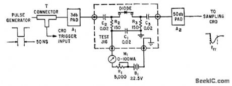
Used in checking performance of computer diodes when handling steep-edged, short-duration pulses. Negative input pulse cuts off diode current, and sampling oscilloscope with 1,000-Mc band-width permits study of diode recovery limes down to 500 picosec.-W. S. Eckess and P. G. Docket, Measurement of Diode Switching Characteristics, Electronics, 33:15, p 59-61. (View)
View full Circuit Diagram | Comments | Reading(866)
Enable_delay_tests
Published:2009/7/23 22:03:00 Author:Jessie
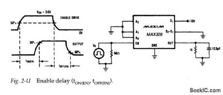
Figure 2-U shows a test circuit for measuring enable time for the MAX328/29. Typical enable turn-on time is 1μs for the MAX328/29M and 1.5μs for the MAX328/ 29C/E. (View)
View full Circuit Diagram | Comments | Reading(657)
5_AND_15_V_SINGLE_CONTROL
Published:2009/7/5 23:52:00 Author:May
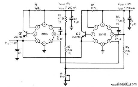
Single poten-tiometer serves for adjusting two reguiators simultaneously, Accuracy depends on output voltage differences of reguiators; error decreases when output voltages are closer Article gives design equation and covers other possiblesources of error.-R C Dobkin, One Adjustment Controls Many Regulators、EDN Magazine, Nov,1,1970 p33-35 (View)
View full Circuit Diagram | Comments | Reading(609)
| Pages:140/312 At 20121122123124125126127128129130131132133134135136137138139140Under 20 |
Circuit Categories
power supply circuit
Amplifier Circuit
Basic Circuit
LED and Light Circuit
Sensor Circuit
Signal Processing
Electrical Equipment Circuit
Control Circuit
Remote Control Circuit
A/D-D/A Converter Circuit
Audio Circuit
Measuring and Test Circuit
Communication Circuit
Computer-Related Circuit
555 Circuit
Automotive Circuit
Repairing Circuit