
Control Circuit
Index 130
LONG_TERM_ELECTRONIC_TIMER
Published:2009/7/7 3:57:00 Author:May
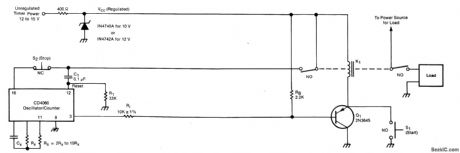
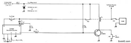
The timer includes an oscillator and a counter in an integrated circuit. The timing interval equals the oscillator period multiplied by the number of cycles to be counted.The oscillator frequency depends upon resistor RS and capacitor CX. The number of oscillator cycles to be counted before the counter output changes state is determined by the selection of the counter output terminal, shown here as pin 3. The interval can be set anywhere in the range from fractions of a second to months; it is given by T = 0.55 RSCX2n, where n is an integer determined by the counter-output selection.Operation is initiated by the closure of momentary switch S1 (or by a command signal having a similar effect). This grounds one side of relay K1, thereby activating the relay and causing the closure of the switches that supply power to the timer and to the load.The turn-on of VCC at the timer is coupled through C1 to the counter-reset terminal, thus resetting the counter. The initial reset voltage transient is then drained away through R1 to permit normal operation. During the first half cycle of the counter operation, the counter output voltage (at pin 3 in this case) is low. This tums on transistor Q1 so that relay K1 latches on, enabling the timer to continue running even though switch S1 has opened. The oscillator runs while the relay is on. When the number of oscillator cycles reaches the limit, the counter output voltage at pin 3 goes high. This tums off Q1, thereby tuming off the relay and returning the system to the original power-off state to await the next starting command. The timing cycle can also be interrupted and the system tumed off by opening normally-closed switch S2. (View)
View full Circuit Diagram | Comments | Reading(1036)
TRANSISTOR_THERMOMETER
Published:2009/7/21 21:21:00 Author:Jessie
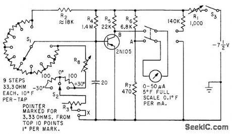
Base bias of germanium transistor varies linearly with temperature over wide ranee, at about 0.0014 v d-c per deg F. Meter is connected to measure base bias and calibrated in degrees for household and outdoor tempera tures. Range switch S1 covers 0 to 100°F in ten steps, and S2 extends range 30°in both directions.-L. E. Barton, Measuring Temperature with Diodes and Transistors, Electronics, 35:18, p 38-40. (View)
View full Circuit Diagram | Comments | Reading(823)
CYRO__TEMPERATURE__CONTROL
Published:2009/7/21 21:19:00 Author:Jessie
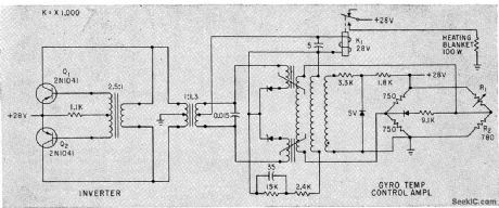
Regulates temperature to 0.5°F by sensing differences between gyro-mounted temperature-sensitive resistor R1 and fixed resistor R2 in bridge. Magnetic amplifier for bridge operates relay K1 to energize gyro heater when temperature is low, -R. E, King and H. Low, Solid-State Guidance For Able-Series Rockets, Electronics, 33:5, p 60-63. (View)
View full Circuit Diagram | Comments | Reading(752)
001℃_DIFFERENTIAL
Published:2009/7/21 20:42:00 Author:Jessie
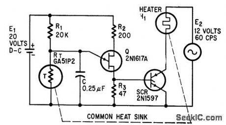
Scr conducts until heater reaches desired temperature, when thermistor T turns off unijunction oscillator Q.-R. G. Ferric, Thermostat Operates With 0.01℃ Differential, Electronics, 37:26, p 65. (View)
View full Circuit Diagram | Comments | Reading(575)
TEMPERATURE_COMPENSATING_THERMOCOUPLE_BRIDGE
Published:2009/7/21 20:41:00 Author:Jessie
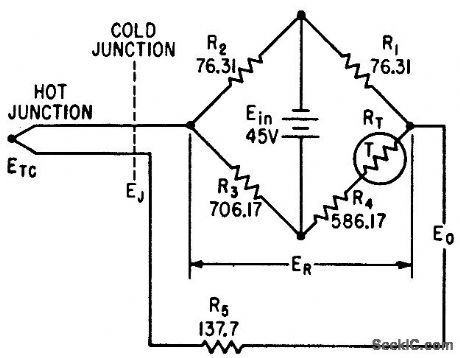
Temperature-sensitive resistor RT in bridge provides voltage to compensate variations in cold-junction voltage during missile light testing.-J. B. Brownwood, Thermocouple Compensating Circuit Design, Electronics, 35:1, p 98-100. (View)
View full Circuit Diagram | Comments | Reading(2144)
PHOTOFEEDBACK_STABILIZATION_OF_PHOTOTRANSISTOR
Published:2009/7/21 20:40:00 Author:Jessie

Subminiature lamp mounted on window of phototransistor stabilizes electro-optical response of high-temperatures. Base bias for phototransistor is supplied by d-c component of light from feedback lamp. -S. A. Elder, Designing Phototransistor Pyrometers With and Without Feedback, Electronics, 34:49, p 56-60. (View)
View full Circuit Diagram | Comments | Reading(897)
MERCURY_THERMOSTAT_AND_SCR_CONTROL_HEATER
Published:2009/7/21 20:39:00 Author:Jessie
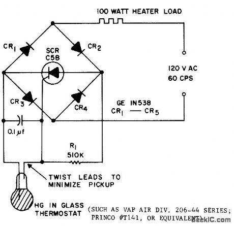
Uses mercury-in-glass thermostat capable of sensing 0.1℃ changes. Scr serves both as current amplifier for thermostat and as main load switching element. With thermostat open, sct will trigger on each half-cycle and deliver power to heater load. When thermostat closes, scr can no longer trigger, and heater shuts off.- Silicon Controlled Rectifier Manual, Third Edition, General Electric Co., 1964, p 121. (View)
View full Circuit Diagram | Comments | Reading(1369)
TEMPERATURE_TELEMETER_FOR_BALLOON
Published:2009/7/21 20:38:00 Author:Jessie

Designed for range of -70 to +70℃, for which circuit produces frequency change of 1.5 kc. Uses temperature-sensitive base-to-emitter voltage of transistor, which varies linearly with temperature, as transducer for voltage-controlled oscillator based on astable mvbr.-G. F. Ingle, Using Transistors for Temperature Measurement, EEE, 11:8, p 53-55. (View)
View full Circuit Diagram | Comments | Reading(694)
CLAMPED_DARLINGTON_CONTROL
Published:2009/7/7 3:48:00 Author:May
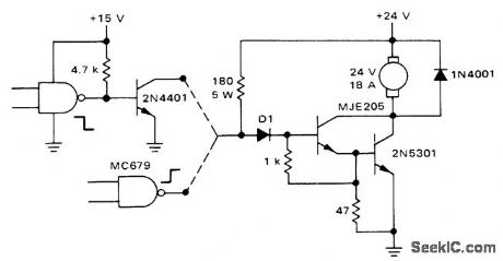
Circuit uses MJE205 5-A transistor in Darlington con-figuration driving 2N5301 30-A transistor for passing 18 A to DC motor under logic control.CMOS gate connections are shown for energizing motor when logic is low and when logic is high.-A. Pshaenich, Interface Techniques Between Industrial Logic and Power Devices, Motorola, Phoenix, AZ, 1975, AN-712A, p 19. (View)
View full Circuit Diagram | Comments | Reading(885)
TRIAC_SPEED_CONTROL_WITH_FEEDBACK
Published:2009/7/7 3:45:00 Author:May

Feedback is derived from load current, eliminating need for separate connections to motor field and armature windings. When triac conducts, normal line voltage less drop across triac and R5 is applied to motor. If firing of triac is delayed in each half of AC cycle, RMS voltage of motor is reduced and speed is correspondingly reduced. Feedback maintains torque at reduced speeds. Value of R5 in ohms is equal to 2 divided by rated RMS motor current in amperes and is 0.32 ohm for 6.5-A induction motor. Suitable for use with electric drills, where good torque is obtained down to about one-third of maximum speed.- Circuit Applications for the Triac, Motorola, Phoenix, AZ, 1971, AN-466, p 7. (View)
View full Circuit Diagram | Comments | Reading(2944)
BODY_TEMPERATURE_TRANSISTOR_THERMOMETER
Published:2009/7/21 21:17:00 Author:Jessie
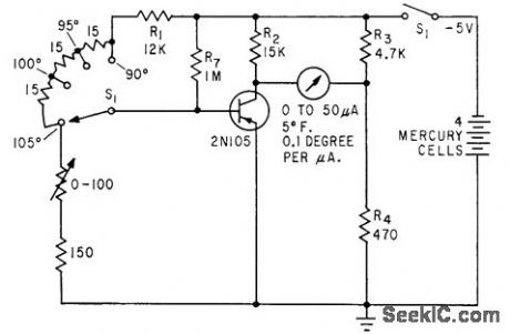
Covers range of 90°to 105°F in three steps, with , temperature indicated on meter that measures base bias of germanium transistor, for which bias varies linearly with temperature.-L. E. Barton, Measuring Temperature with Diodes and Transistors, Electronics, 35:18, p 38-40. (View)
View full Circuit Diagram | Comments | Reading(929)
WIDE_RANGE_DIODE_THERMOMETER
Published:2009/7/21 21:14:00 Author:Jessie
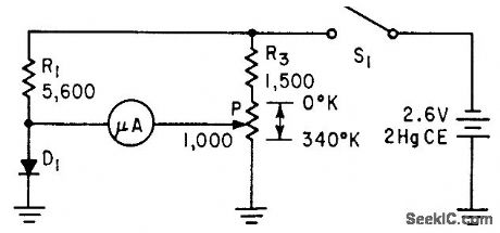
Temperature-sensing germanium-diode bucking-vott-age microammeter has null indicator, covers full usable range of from near absolute zero to about 45℃ with resistance values shown. -L. E. Barton, Measuring Temperature with Diodes and Transistors, Electronics, 35:18, p 38-40. (View)
View full Circuit Diagram | Comments | Reading(819)
TEMPERATURE_TRANSMlTTER
Published:2009/7/21 20:55:00 Author:Jessie
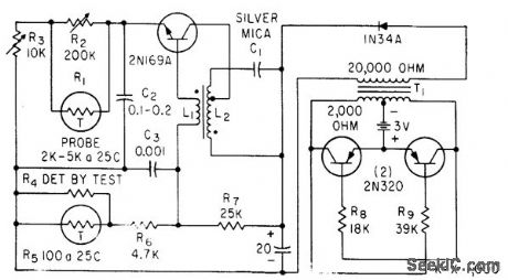
2N169A transistor is used in tuned-collector oscillator, with large R.C time constant in emitter drcuit to give self-modulator for quenching action. Variation in quench break is accomplished with temperature-sensing element R1, consisting of glass-enclosed bead thermistor.-R. H. Elsken, Temperature Telemetry Aids Frozen Food Study, Electronics, 33:33, p 129-131. (View)
View full Circuit Diagram | Comments | Reading(862)
MEASURING_HIGH_TEMPERATURES
Published:2009/7/21 20:51:00 Author:Jessie
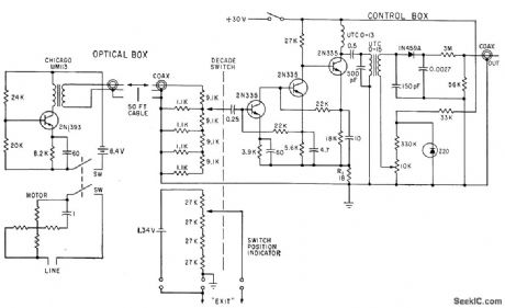
Used for automatic recording of missile und rocket surface temperatures. Phototransistor, connected in common-emitter mode, requires no preamp. Decade amplifier in control box is stabilized by 34 db of feedback through R1. Diode demodulator provides d-c output for recording.-S. A. Elder, Designing Photo. transistor Pyrometers With and Without Feed. bock, Electronics, 34:49, p 56-60.
(View)
View full Circuit Diagram | Comments | Reading(1140)
TRANSISTORS_SENSE_TEMPERATURE
Published:2009/7/21 20:45:00 Author:Jessie
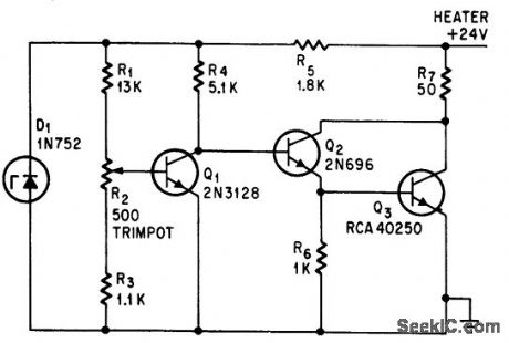
Transistor Q1, nounted in tight thermal contact with heater R7, will maintain crystal oven within 0.2℃ of 70℃.-S. Greenblatt, Transistor Be-comes Sensor In Temperature Regulator, Electronics, 37:28, p 65. (View)
View full Circuit Diagram | Comments | Reading(1076)
SIMPLE_DIODE_SENSOR
Published:2009/7/21 20:44:00 Author:Jessie
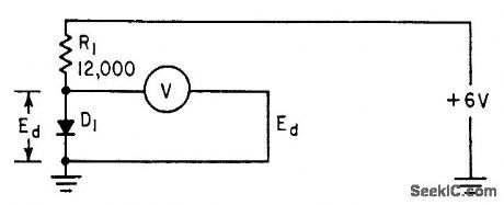
Meter measures voltage drop across germanium diode (such as 1N2326), which varies linearly with temperature from near absolute zero to a high limit around 45℃, which is upper limit of diode base material.-L. E. Barton, Measuring Temperature with Diodes and Transistors, Electronics, 35;18, p 38-40. (View)
View full Circuit Diagram | Comments | Reading(802)
MANUALLY_CONTROLLED_SIREN
Published:2009/7/22 1:12:00 Author:Jessie
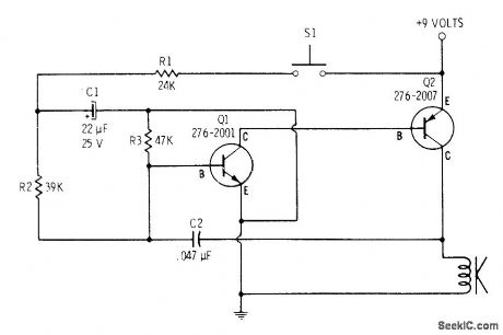
When switch is pressed, output tone of loudspeaker builds from low to high frequency. Releasing switch brings high frequency slowly back to low point and then cutoff. Siren sounds can be varied manually by pushing and releasing switch at different points in cycle.C2 controls pitch, and R3 determines speed at which pitch changes.-F. M. Mims, Transistor Projects, Vol. 1, Radio Shack, Fort Worth, TX, 1977, 2nd Ed. p 58-63. (View)
View full Circuit Diagram | Comments | Reading(674)
TRANSFORMERLESS_LINEAR_MODULATOR
Published:2009/7/22 1:11:00 Author:Jessie
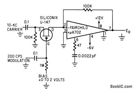
Integrated-circuit operational amplifier and field effect transistor in single-ended linear configuration eliminate need for filter and transformer. Carrier level is adjusted by changing d-c bias, which sets gate midway between zero bias and pinchoff.-J. Althouse, linear Amplifier Circuit Eliminates Transformers, Electronics, 39:6, p 99. (View)
View full Circuit Diagram | Comments | Reading(615)
10_W_AUTO_ALARM_SIREN
Published:2009/7/21 23:16:00 Author:Jessie
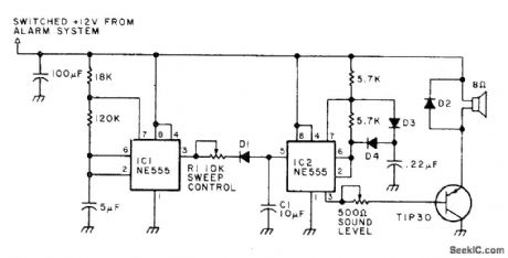
Generates force field of high-intensity sound inside car, painful enough to discourage thief from entering car after tripping alarm switch by opening door.Circuit produces square-wave output that sweeps up and down in frequency. Modulation is provided by triangle waveform generated by R1, D1, and C1. If sweep-frequency siren is prohibited, remove C1 to produce legal two-tone sound. Use efficient horn loudspeaker capable of handling up to 10W. D2 is silicon rectifier rated 1 A at 50 PIV. Other diodes are general-purpose silicon.-A. T. Roderick III, New Protection for Your Car, 73 Magazine, March 1978, p 76-77. (View)
View full Circuit Diagram | Comments | Reading(799)
UP_TO_SPEED_LOGIC
Published:2009/7/7 3:26:00 Author:May
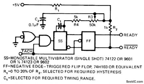
Simple speed-sensing circuit fed by tachometer pulses makes READY output high when rotating device reaches desired minimum or threshold speed. Single-action triggering eliminates instability at decisionpoint. Circuit also provides hysteresis, for separating pull-in and drop-out points any desired amount as determined by ratio of R1 to R2 in timing network. Article covers circuit operation and gives timing diagram.-W. Bleher, Circuit Indicates Logic Ready, EDN Magazine, March 5, 1974, p 72 and 74. (View)
View full Circuit Diagram | Comments | Reading(801)
| Pages:130/312 At 20121122123124125126127128129130131132133134135136137138139140Under 20 |
Circuit Categories
power supply circuit
Amplifier Circuit
Basic Circuit
LED and Light Circuit
Sensor Circuit
Signal Processing
Electrical Equipment Circuit
Control Circuit
Remote Control Circuit
A/D-D/A Converter Circuit
Audio Circuit
Measuring and Test Circuit
Communication Circuit
Computer-Related Circuit
555 Circuit
Automotive Circuit
Repairing Circuit