
Control Circuit
Index 125
PROPORTIONAL_CONTROL_FOR_OVEN
Published:2009/7/8 1:32:00 Author:May
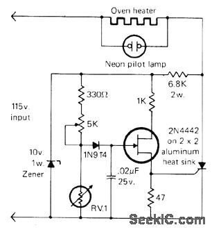
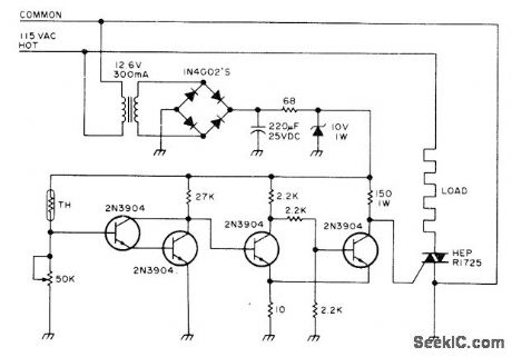
Thermistor RV1 and resistor-pot combination form voltage divider across 10-V zener, with output applied to UJT. Voltage across capacitor is ramp during positive half-eycles of AC Iine, slope of which is function of temperature and setting of 5K pot, When ramp reaches firing voltage of UJT, it turns on SCR and applies power to load, Negative half of AC input tums off SCR and cycle repeats. When oven temperature is low, SCR fires early in cycle to give more heat. When preset temperature is reached, SCR fires very late in cycle to compensate for heat lost by oven. Designed for 100'F environmental test chamber.-I. Math, Math's Notes, CQ, Sept. 1978, p 63 and 82-83.
(View)
View full Circuit Diagram | Comments | Reading(957)
PIEZOELECTRIC_FAN_BASED_TEMPERATURE_CONTROLLER
Published:2009/7/7 23:18:00 Author:May
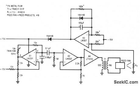
The fan employed is one of the new electrostatic type which is very retable, because it contains no wearing parts. These devices require high-voltage drive. When power is applied, the thermistor, located in the fan's exhaust stream, is at a high value. This value unbalances the A3 amplifier driven bridge. A1 receives no power and the fan does not run. As the instrument enclosure warms, the thermistor value decreases until A3 begins to oscillate. A2 provides isolation and gain, and A4 drives the transformer to generate high voltage for the fan. In this fashion, the loop acts to maintain a stable instrument temperature by controlling the fm's exhaust rate. The 100-μF time constant across the error amplifier pins is typical of such configurations. Fast time constants will produce audibly annoying hunting in the servo. Optimal values for this time constant and gain depend upon the thermal and airflow characteristics of the enclosure being controlled. (View)
View full Circuit Diagram | Comments | Reading(866)
PROPORTIONAL_TEMPERATURE_CONTROLLER
Published:2009/7/7 23:13:00 Author:May
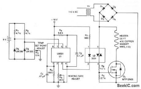
This temperature controller operates as a fiulse snatching device, which allows it to run at its own speed and turn on at the zero crossing of the line frequency. Zero crossing turn-on reduces the generation of line noise transients. TMOS Power FET, Q1, is used to turn on a heater.
Temperature sensor D6 provides a dc voltage proportional to temperature that is applied to voltage-to-frequency converter U1. Output from U1 is a pulse train proportional to temperature offset that is applied to the input of triac optoisolator U2. The anode supply for the triac is a 28 V pk-pk, full-wave rectifted sine wave. The optoisolator ORs the pulse train from U1 with the zero crossing of U2's anode supply, supplying a gate tum on signal for Q1. Therefore, TMOS power FET Q1 can only turn the heater on at the zero crossing of the applied sine wave. The maximum temperature, limited by the sensor and the insulation of the wire, is 130°C for the components shown. (View)
View full Circuit Diagram | Comments | Reading(3170)
CURRENT_MONITOR_AND_ALARM
Published:2009/7/7 23:11:00 Author:May
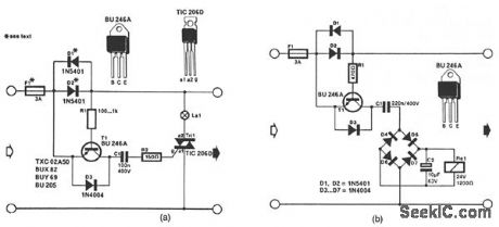
The circuit in Fig. 56-11a lights the signal lamp upon detecting a line current consumption of more than 5 mA, and handles currents of several amperes with appropriate diodes fitted in the Dl and D2 positions. Transistor T1 is switched on when the drop across D1/D2 exceeds a certain level. Diodes from the well-known 1N400x series can be used for currents of up to 1 A, while 1N540x types are rated for up to 3 A. Fuse Fl should suit the particular application.The circuit in Fig. 56-11b is a current-triggered alarm. Rectifier bridge D4 through D7 can only provide the coil voltage for Rel when the current through D1/D2 exceeds a certain level, because then series capacitor C1 passes the alternating main current. Capacitor C1 needs to suit the sensitivity of the relay coil. This is readily effected by connecting capacitors in parallel until the coil voltage is high enough for the relay to operate reliably. (View)
View full Circuit Diagram | Comments | Reading(1277)
TEMPERATURE_CONTROLLER
Published:2009/7/7 23:07:00 Author:May
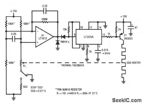
When power is applied, the thermistor, a negative tc device, is at a high value. A1 saturates positive.This forces the LT3525A switching regulator's output low, biasing Q1. As the heater warms, the thermistor's value decreases. When its inputs finally balance, A1 comes out of saturation and the LT3525A pulsewidth modulates the heater via Q1, completing a feedback path. A1 provides gain and the LT3525A is highly efficient. The 2-kHz, pulse-width modulated heater power is much faster than the thermal loop's response, and the oven sees an even, continuous heat flow. (View)
View full Circuit Diagram | Comments | Reading(0)
SERVO_SENSED_HEATER_PROTECTOR
Published:2009/7/7 23:03:00 Author:May
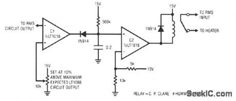
This circuit responds quickly enough to prevent damage from most overloads. C1's input is connected to the output of the LT10ss servo circuit. If the LT1088 circuit's output exceeds the threshold at C1's other input, C1 trips, discharging the 2-μF capacitor. This causes C2's output to become low, energize the relay, and break the heater circuit. The 560-KΩ resistor provides a long recharge for the capacitor, preventing chattering action. This arrangement's speed of response is limited by the rms circuit's slew rate, about 0.2 V/ms. For reasonable overloads, the LT1088's temperature increases about 1°C/ms. A 10-V LT1088 output step takes 50 ms, causing a temperature rise of about 50°C. (View)
View full Circuit Diagram | Comments | Reading(791)
ZERO_POINT_SWITCHING_TEMPERATURE_CONTROL
Published:2009/7/7 22:58:00 Author:May
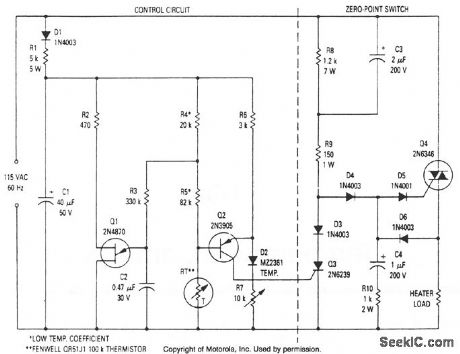
This modulated triac zero-point switching circuit controls heater loads operating from 115 Vac. Circuit operation is best described by splitting the circuit into two parts. The circuit at right is the zero-point switch; to the left is the proportional control for the zero-point switch. (View)
View full Circuit Diagram | Comments | Reading(939)
ON_OFF_HEATER_CONTROL
Published:2009/7/7 22:57:00 Author:May
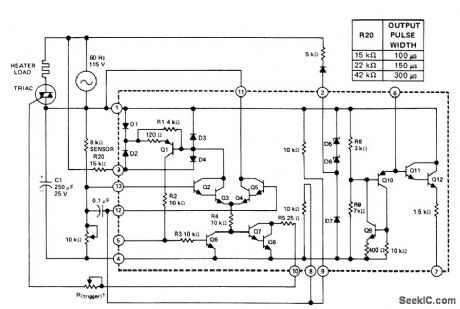
Uses Texas In-struments SN72440 zero-voltage switch to trigger triac that turns AC heater on and off in acl cordance with demands of 8K resistance-type temperature sensor. One output pulse per zero crossing of AC Iine voltage is either inhibited or permitted by action of differential amplifier and resistance bridge circuit in IC. Width of output pulse at pin10 is controlled by trigger pot R20 as given in table and should be varied to suit triggering characteristics of triac used.- The Linear and Interface Circuits Data Book for Deislgn Engineers, Texas Instruments,Dallas,TX,1973,p7-37
(View)
View full Circuit Diagram | Comments | Reading(1259)
75_250℃_OVEN_CONTROL
Published:2009/7/7 22:55:00 Author:May
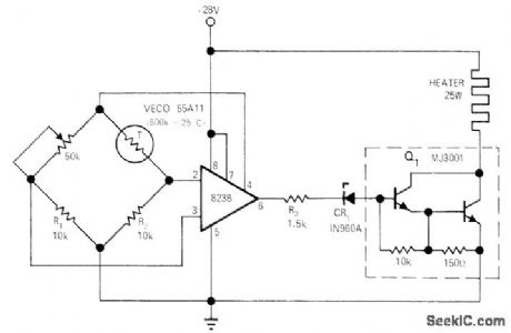
Provides propor-tional temperature control of small oven to within 1℃ over temperature range. Uses 823B voltage regulator operating from same 28-V source as oven. Temperature-setting pot should be 10-turn wirewound. Powertransistor Q1operates either saturated or almost cut off, so no heatsink is required.-R. L. Wilbur, Pro-portional Oven-Temperature Controller, EDNlEEEMagazine, Sept. 15, 1971, p 45. (View)
View full Circuit Diagram | Comments | Reading(747)
OVEN_CONTROL
Published:2009/7/7 22:52:00 Author:May
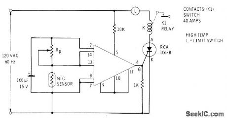
Simple circuit using RCA CA3059 zero-crossing switch regulates ON and OFF intervals of low-current SCR that controls solenoid in electric or gas oven. Sensor resistor has negative temperature coefficient. RP, is set for desired control temperature.-E. M. Noll, Linear IC Principles, Experiments, and Proj-ects, Howard W. Sams, Indianapolis, IN, 1974, p323.
(View)
View full Circuit Diagram | Comments | Reading(2225)
PROPORTIONING_CONTROLLER
Published:2009/7/7 22:50:00 Author:May
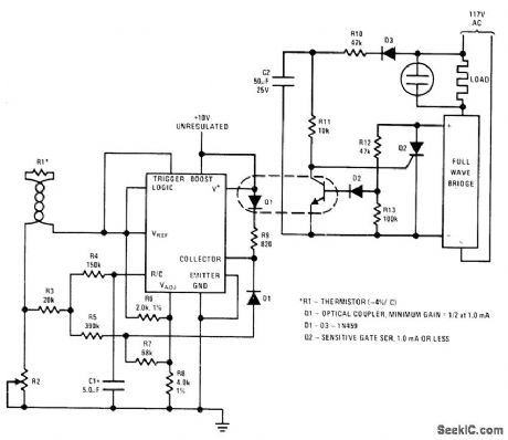
National LM122 timer is used as proportioning temperature controller with optical isolation and synchronized zero-crossing. R2 is used to set tem-perature to be controlled by thermistor R1. SCR used for Q2 is chosen to handle required load.D3 is rated at 200 V. R12, R13, and D2 implement synchronized zero-crossing feature.-C. Nelson, Versatile Timer Operates from Microseconds to Hours, National S_emiconductor, Santa Clara, CA, 1973, AN-97, p 8.
(View)
View full Circuit Diagram | Comments | Reading(752)
COOKER_CONTROL
Published:2009/7/7 22:48:00 Author:May
Uses Model K600A thermistor (Allied Electronics) placed in slow cooker to maintain ideal cooking temperature. Pot can be adjusted to provide triggering for ON/OFF control of heating element for cooker, Use polarized power plug for proper operation.-Circuits, 73Magazine, May 1977, p 19. (View)
View full Circuit Diagram | Comments | Reading(1283)
LINE_ACTIVATED_SOLID_STATE_SWITCH
Published:2009/7/7 22:27:00 Author:May
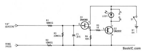
Each and every time a phone on the same line or calling number is taken off-hook, the circuit will be activated to control an extemal electronic circuit. If several extension telephones are used.on one phone line, the circuit can be useful as a busy indicator. LED1 contains a special flashing red LED that makes an excellent indicator for a busy circuit condition.The solid-state switch can be used for several other phone-activated applications, such as automatically tuming on a cassette recorder, starting a phone-use timer or counter, etc. A small relay can be connected at points A and B, in place of LED1, to control extemal circuits. A 117-Vac-to-6-Vdc plug-in power supply can be substituted for the battery to keep the operating cost at a minimum.The 48-Vdc, on-hook, phone-line voltage keeps Q1 in the cut-off condition, allowing no current to flow through resistor R4, hence Q2 remains off. Resistors R1 and R2 keep the solid-state switch circuit from causing any problems with the telephone's central-office equipment. When a phone is taken off-hook, the line voltage (tip to ring) drops to 10 V or less, which forces Q1 to turn on; this, in turn, causes Q2 to trigger LED1, or a relay which might be used in lieu of LED1. (View)
View full Circuit Diagram | Comments | Reading(1272)
MODEL_TRAIN_SWITCHING
Published:2009/7/7 21:58:00 Author:May
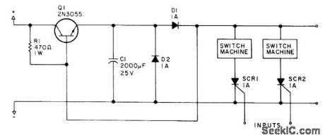
individual SCRs are triggered by logic-level signals independently to initiate discharge of large capacitor C1 through solenoid of model railroad tracks witch.-D. W. zimmerli,Two Hobbies:Model Railroading and Computing,Kilobaud Aug1978,p 62-68. (View)
View full Circuit Diagram | Comments | Reading(1014)
MULTIPLEXING_BCD_SWITCHES
Published:2009/7/7 21:40:00 Author:May
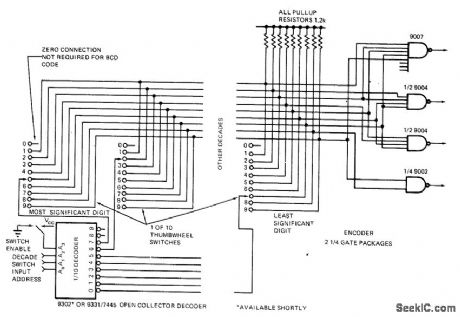
Multiplexing technique reduces number of interconnections between thumbwheel switches and counters, displays, or industrial control equipment being programmed remotely Ten decades of BCD switches require only 10 interconnections, as compared to 50 without multiplexing, All 10outputs of low-cost single-pole decade switches are paralleled. with wiper arm connections being brought out separately Parallel outputs are fed into simple encoder using four NAND gates to generate4-bit BCD output code. Wiper of each switch is addressed from active low open-collector decoder. In operation,3-bit input address determines which decade switch is addressed, and switch position then determines which encoder NAND gates are activated.-E. Breeze, Putting the, ”Thumb″ on Thumbwheel Switch Multiplexing, EDN Magazine, Aug,1,1972, p56. (View)
View full Circuit Diagram | Comments | Reading(1568)
PHOTOELECTRIC_AC_POWER_SWITCH
Published:2009/7/7 21:32:00 Author:May
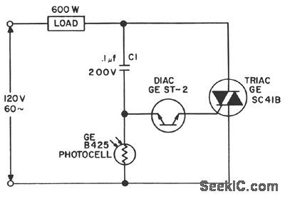
For a dark photocell, high resistance, the voltage across the diac rises rapidly with the line voltage due to the current through C1, triggering the diac early in the cycle.When the photocell resistance is less than about 2000 Ω,the drop across it is limited to less than the diac triggering voltage,and the load power is shut off. (View)
View full Circuit Diagram | Comments | Reading(1794)
SOLAR_TRIGGERED_SWITCH
Published:2009/7/7 21:28:00 Author:May

View full Circuit Diagram | Comments | Reading(726)
LIGHTED_DISPLAY_BRIGHTNESS_CONTROL
Published:2009/7/7 21:24:00 Author:May
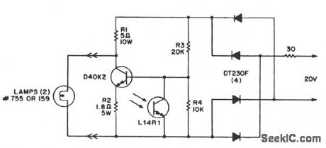
This circuit provides a very low cost method of controlling light levels. Circuit power is obtained from a relatively high source impedance transformer or motor windings, normally used to drive the low-voltage lamps used in these functions. It should be noted that the bias resistors are optimized for the 20-V, 30-Ω source, and they must be recalculated for other sources. The L14R1 is placed to receive the same ambient illumination as the display and should be shielded from the light of the display lamps. The illumination level of lighted displays should be lowered as the room ambient light dims, to avoid undesirable or unpleasant visual effects.
(View)
View full Circuit Diagram | Comments | Reading(666)
LIGHT-CONTROLLED_LAMP_SWITCH
Published:2009/7/7 21:16:00 Author:May
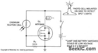
A school drama needed lamps that automatically turned on and off when spot lights did the same.Lamp switching had to be wireless, durable, dependable, simple and inexpensive. With stage and spot lights off, very little light falls on the CdS photocell, so its internal resistance is several megohms and R1 keeps the gate of Q1 at nearly zero volts, which keeps it off. When a spot or stage light hits the photocell, its resistance drops to several hundred ohms, raising Q1's gate voltage, which turns it on and applies power to the lamp. (View)
View full Circuit Diagram | Comments | Reading(1007)
TV_GAME_CONTROLLER
Published:2009/7/7 20:45:00 Author:May
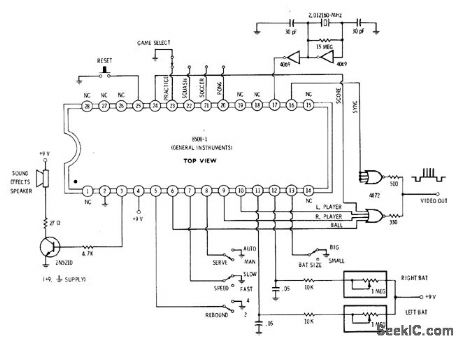
Single General Instruments 8500 lC contains most of electronics needed for pong, hockey, squash, or practice games using screen of TV set. Desired game is selected by grounding one of pins 20-23. Connect ball, player, and score outputs to four-input 0R circuit to generate composite video for com bining with sync output. Final output can be fed directly to video amplifier of TV set or fed to suitable RF modulator. Sound output is fed to Ioudspeaker through transistor audio amplifier.No connection on pin 5 gives two rebound angles, while grounding gives four rebound an gles. Open pin 7 gives fast speed, and grounding gives slow speed. 0pen pin 13 gives small bats, and grounding gives large bats.-D. Lan-caster, CMOS Cookbook, Howard W. Sams, Indianapolis, IN, 1977, p 166. (View)
View full Circuit Diagram | Comments | Reading(1141)
| Pages:125/312 At 20121122123124125126127128129130131132133134135136137138139140Under 20 |
Circuit Categories
power supply circuit
Amplifier Circuit
Basic Circuit
LED and Light Circuit
Sensor Circuit
Signal Processing
Electrical Equipment Circuit
Control Circuit
Remote Control Circuit
A/D-D/A Converter Circuit
Audio Circuit
Measuring and Test Circuit
Communication Circuit
Computer-Related Circuit
555 Circuit
Automotive Circuit
Repairing Circuit