
Control Circuit
Index 123
HIGH_EFFICIENCY_MOTOR_SPEED_CONTROLLER
Published:2009/7/8 5:17:00 Author:May
View full Circuit Diagram | Comments | Reading(825)
_PWM_MOTOR_CONTROLLER
Published:2009/7/8 5:14:00 Author:May
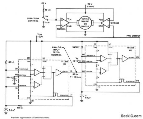
The PWM controller uses complementary half-H peripheral drivers SN75603 and SN75604, with totem-pole outputs rated at 40 V and 2.0 A. These drivers effectively place the motor in a full-bridge configuration, which has the ability to provide bidirectional control.
Timer U1 operates in the astable mode at a frequency of 80 Hz. The 100-Ω discharge resistor results in an 8-μs trigger pulse which is coupled to the trigger input of timer U2. Timer U2 serves as the PWM generator. Capacitor C1 is charged linearly with a constant current of 1 mA from the 1N5297, which is an FET current-regulator diode.
Motor speed is controlled by feeding a dc voltage of 0 to 10 V to control input pin 5 of U2. As the control voltage increases, the width of the output pulse pin 3 also increases. These pulses control the on/off time of the two motor drivers. The trigger pulse width of timer U1 limits the minimum possible duty cycle from U2. (View)
View full Circuit Diagram | Comments | Reading(1824)
DC_MOTOR_DRIVE_WITH_FIXED_SPEED_CONTROL
Published:2009/7/8 5:07:00 Author:May
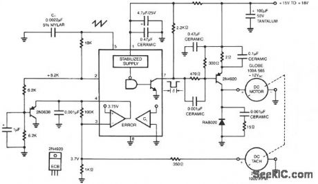
The NE5561 provides pulse-proportional drive and speed control based on dc tachometer feedback. This simple switching circuit consists of transistor 2N4920 pnp with a commutation diode used to deliver programmed pulse energy to the motor. A frequency of approximately 20 kHz is used to eliminate audio noise. The dc tach delivers 2.7V/1000 RPM. Negative feedback occurs when this voltage is applied to the error amplifier of the NE5561. The duty cycle varies directly with load torque demand. The no-load current is≈ 0.3 A and full load is 0.6 A. (View)
View full Circuit Diagram | Comments | Reading(2235)
AUTONATIC_FAN_SPEED_CONTROLLER
Published:2009/7/8 4:54:00 Author:May
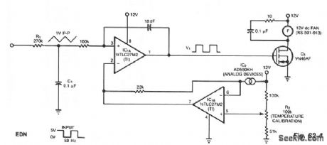
The controller circuit can reduce a fan's noise, power consumption, and wear, particularly in the presence of a low, fluctuating ambient temperature. Mount a temperature sensor in the fan's airstream, and the circuit will adjust the fan speed as necessary to maintain a relatively constant sensor temperature.Input components R1 and C1 integrate the input square wave, producing a quasitriangular wave at the noninverting input of op amp IC1A. At this inverting input is a reference voltage that decreases as temperature increases. The two-terminal sensor produces 1 μA/°K. The result is a rectangular wave at the output of IC1A with a duty cycle proportional to absolute temperature. Thus, a rise in temperature triggers a counter acting cooling effect by delivering more power to the fan. To calibrate the system with the sensor at room temperature, simply adjust R2 for a 50% duty cycle at V1. The fan will switch off at approximately 0℃ and will be fully on at 44℃. (View)
View full Circuit Diagram | Comments | Reading(815)
LINE_OPERATED_POWER_OUTAGE_LIGHT
Published:2009/7/8 22:48:00 Author:Jessie
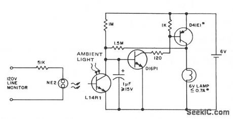
This circuit provides emergency lighting during a power outage. The phototransistor should be positioned to maximize coupling of both neon light and ambient light into the pellet, without allowing self-illumination from the 6-V lamp. Many circuits of this type also use line voltage to charge the battery.
(View)
View full Circuit Diagram | Comments | Reading(1044)
3_1_2_digit_multiplexed_MLC401_field_effect_LCD
Published:2009/7/20 21:52:00 Author:Jessie
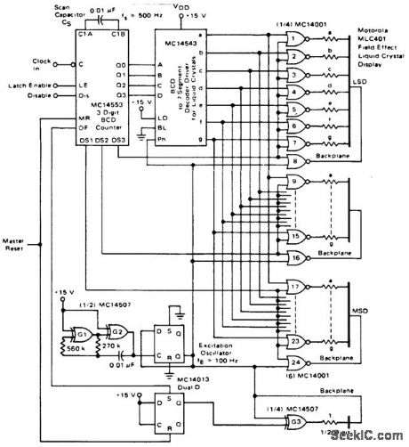
3 1/2-digit multiplexed MLC401 field-effect LCD(courtesy Motorola Semiconductor Products Inc.). (View)
View full Circuit Diagram | Comments | Reading(786)
TACHOMETERLESS_SERVO
Published:2009/7/20 22:26:00 Author:Jessie
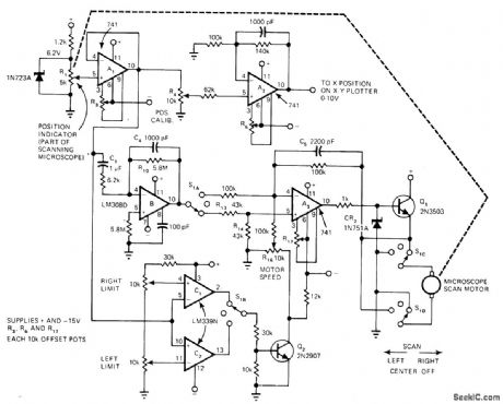
Developed to provide speed control for motor enclosed in such a way that tachometer cannot be used for feedback Position pot R1 and differentiator B substitute for tachometer in controlling rate of scanning-microscope eyepiece used for measuring CRT line width. Buffer A1 feeds X input of XY plotter through opamp A2, and also feeds differentiator B and limit-detector voltage comparator C1-C2. S1 switches A3 between inverting and noninverting operation each time scanning direction changes, to keep feedback negative.-H. F. Stearns, Differentiator and Position Pot Sub for Tachometer, EDN Magazine, Aug. 5, 1977, p 50-52. (View)
View full Circuit Diagram | Comments | Reading(1075)
DARLINGTON_PHASE_SHIFTER
Published:2009/7/20 22:43:00 Author:Jessie
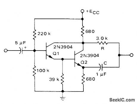
Basic 90°push-pull RC phase shifter using discrete transistors is connected as phase-splitting amplifier Used at output of follow-up pot in servo amplifier driving 115-V 60-Hz servomotor Supply is 28 V Motorola MPSA13 Darlington IC can be used if 39K resistor is omitted.-A, Pshaenich, Servo Motor Drive Amplifiers, Motorola,Phoenix,AZ,1972,AN-590. (View)
View full Circuit Diagram | Comments | Reading(2055)
TTL_SERVO_CONTROL
Published:2009/7/20 22:42:00 Author:Jessie
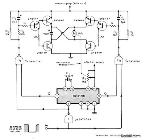
Used in nine-channel remote control system having nine identical servos fed by decoder at receiving end of data link. Variable-width pulse command from decoder is fed into TTL IC pulse-width comparator that feeds bridge-type motor drive. Command pulse controls both direction and duration of motor rotation. Article describes operation in detail and gives associated coder and decoder circuits.-M. F. Bessant, Multi-Channel Proportional Remote Control, Wireless World, Oct.1973, p 479-482. (View)
View full Circuit Diagram | Comments | Reading(2154)
27_MHz_AGC_able_self_oscillating_mixer_for_CB_operation_using_a_TIS148_dual_gate_MOSFET
Published:2009/7/20 22:42:00 Author:Jessie
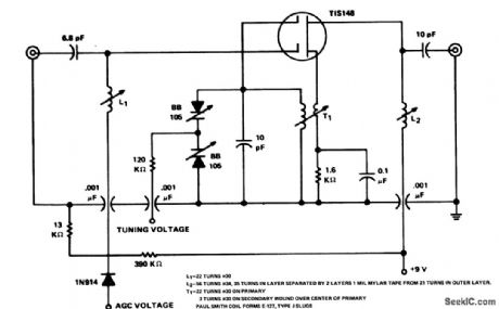
27 MHz AGC-able self-oscillating mixer for CB operation using a TIS148 dual gate MOSFET (courtesy Texas Instruments Incorporated). (View)
View full Circuit Diagram | Comments | Reading(888)
MUSCLE__POTENTIAL__TELEMETER
Published:2009/7/20 23:25:00 Author:Jessie
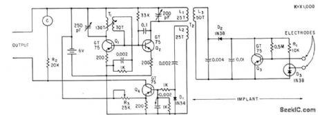
Implanted probe circuit receives power at 50 kc from external pickup coil driven by modified Hartley oscillator Q1. Signal is rectified by D2 to provide d-c power for Q3, to generate magnetic field that varies with muscle potential .-S. Bagno, F. Liebman, and F. Cosenza, Detecting Muscle Potentials in Unanesthetized Animals, Electronics, 33:41, p 58-59. (View)
View full Circuit Diagram | Comments | Reading(612)
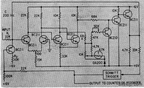
PULSE_AMPLIFIER_FOR_HEART
Published:2009/7/20 23:23:00 Author:Jessie
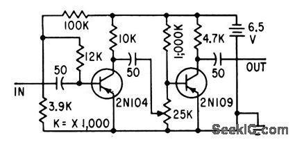
Used to provide adequate stimulating voltage to electrode sewn on ventricle of heart to make it contract properly in heart-blocked patients. Command pulses from electrode on auricle are amplified 200 times by circuit, without waveform distortion, and applied to ventricle electrodes to produce normal pumping rhythm.-G. F. Vanderschmidt, Two-Transistor Amplifier Corrects Heart Block, Electronics, 31:47, p 80-81. (View)
View full Circuit Diagram | Comments | Reading(720)
RETINA_WELD_TIMER
Published:2009/7/20 23:22:00 Author:Jessie
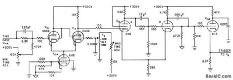
Time base ramp volt-age is fed to trigger pickoff circuit V16-V17-V19A. Delay time potentiometer R4 deter-mines voltage at which V17 conducts. Delayed pulse is fed to trigger-shaping mvbr V18 which feeds strong, fast pulse to V198 to give output for firing thyratron that turns off r-f power.-O. Rich, Jr. and R. V. Hill, R-F Spot Welder Reattaches Retina of Human Eye, Electronics, 34:32, p 160-163. (View)
View full Circuit Diagram | Comments | Reading(772)
TACHLESS_MOTOR_SPEED_CONTROLLER
Published:2009/7/8 5:04:00 Author:May
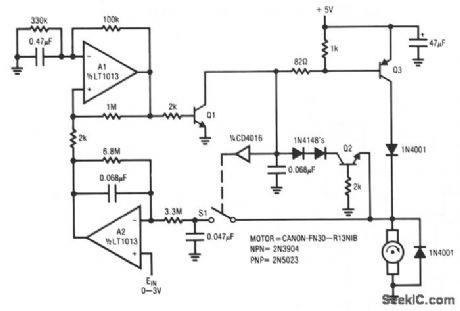
This circuit is particularly applicable to digitally-controlled systems in robotic and X-Y positioning applications. By functioning from the 5-V logic supply, it eliminates additional motor-drive supplies. The tachless feedback saves additional space and cost. The circuit senses the motor's back EMF to determine its speed. The difference between the speed and a set point is used to close a sampled loop around the motor. A1 generates a pulse train. When A1's output is high, Q1 is biased, and Q3 drives the motor's ungrounded terminal. When Al decreases, Q3 turns off and the motor's back EMF appears after the inductive flyback ceases. During this period, S1's input is turned on, and the 0.047-μF capacitor acquires the back EMF's value. A2 compares this value with the set point and the amplified difference (trace D) changes Al's duty cycle, controlling the motor speed. (View)
View full Circuit Diagram | Comments | Reading(0)
CLOSED_LOOP_MOTOR_SPEED_CONTROL
Published:2009/7/8 5:01:00 Author:May
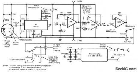
This electronic motor-speed control circuit is designed to operate in an electrically noisy environment.The circuit includes an optoelectronic pickup device, which is placed inside the motor housing to provide a speed feedback signal. The circuit automatically maintains the speed of the motor at the commanded value.
The pickup device contains an infrared LED and a phototransistor. The radiation from the diode is chopped into pulses by the motor fan blades, which are detected by the phototransistor. The train of pulses from the phototransistor is fed to a frequency-to-voltage converter, the output of which is a voltage proportional to the speed of the motor. This voltage is low-pass filtered, amplified, and compared with a manually-adjustable control voltage that represents the commanded speed.
The difference between the speed-measurement and speed-command signals is amplified and fed as a control voltage to an external power amplifier that drives the motor. A selector switch at the output of the final amplifier of this circuit also enables the operator to bypass the circuit and manually set the control voltage for the external amplifier. (View)
View full Circuit Diagram | Comments | Reading(976)
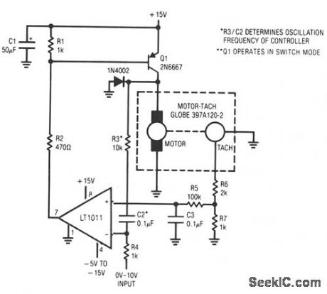
SWITCHED_MODE_MOTOR_SPEED_CONTROLLER
Published:2009/7/8 4:59:00 Author:May
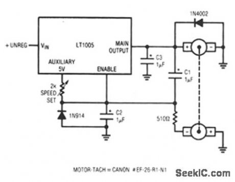
This circuit uses a tachometer to generate a feedback signal which is compared to a reference supplied by the auxiliary output. When power is applied, the tachometer output is zero and the regulator output comes on, forcing current into the motor. As motor rotation increases, the negative tachometer output pulls the enable pin toward ground. When the enable pin's threshold voltage is reached, the regulator output decreases and the motor slows. C1 provides positive feedback, ensuring clean transitions. In this fashion, the motor's speed is servo-controlled at a point determined by the 2-KΩ) potentiometer setting. The regulator free-runs at whatever frequency and duty cycle are required to maintain the enable pin at its threshold.The loop bandwidth and stability are set by C2 and C3. The 1N914 diode prevents the negative output tachometer from pulling the enable pin below ground, and the 1N4002 commutates the motor's negative flyback pulse. (View)
View full Circuit Diagram | Comments | Reading(793)
SERVO_SYSTEM_CONTROLLER
Published:2009/7/8 4:57:00 Author:May
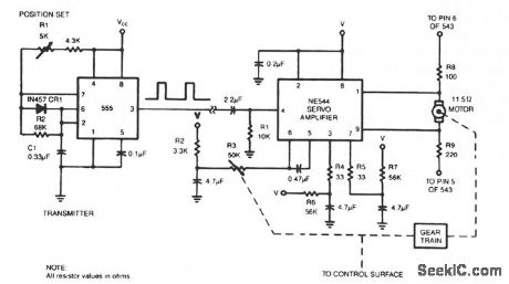
To control a servo motor remotely, the 555 needs only six extra components. (View)
View full Circuit Diagram | Comments | Reading(2922)
EFFICIENT_SWITCHING_CONTROLLER
Published:2009/7/8 4:56:00 Author:May
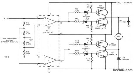
This high-performance switching controller for a low-power dc servo motor uses a symmetrical complementary-transistor bridge. The bridge acts as a reversing switch between the motor and a single-ended power supply. Since the transistors operate either fully on or completely off, except during a very short transition period, much less heat is dissipated than in linear-amplifier circuits. Damping is provided by the circuit's inherent dynamic braking. Since either maximum or zero voltage is applied to the motor, the dynamic response is faster than that of linear servo drives. (View)
View full Circuit Diagram | Comments | Reading(2575)
Half_wave_synchronous_rectification_circuit
Published:2009/7/21 3:20:00 Author:Jessie
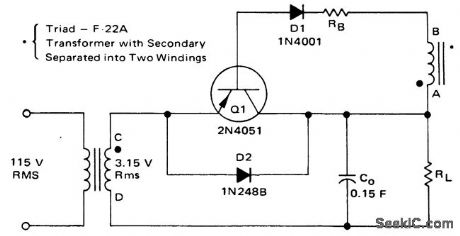
Half-wave synchronous rectification circuit (courtesy Motorola Semiconductor Products Inc.). (View)
View full Circuit Diagram | Comments | Reading(643)
Automaticgain_control_circuit
Published:2009/7/21 3:19:00 Author:Jessie
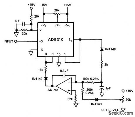
Automaticgain control circuit. The AD531 programmable multiplier/divider maintains a 3-volt peak-to-peak output for inputs from 0.1 volt to over 12 volts with 2% regulation for the range from 0.4 volt peak to peak to 6 volts peak to peak. The input frequency can range from 30 hertz to 400 hertz (courtesy Analog Devices, Inc.). (View)
View full Circuit Diagram | Comments | Reading(697)
| Pages:123/312 At 20121122123124125126127128129130131132133134135136137138139140Under 20 |
Circuit Categories
power supply circuit
Amplifier Circuit
Basic Circuit
LED and Light Circuit
Sensor Circuit
Signal Processing
Electrical Equipment Circuit
Control Circuit
Remote Control Circuit
A/D-D/A Converter Circuit
Audio Circuit
Measuring and Test Circuit
Communication Circuit
Computer-Related Circuit
555 Circuit
Automotive Circuit
Repairing Circuit