
Control Circuit
Index 137
GOVERNOR_TRANSISTOR_SPEED_REGULATOR
Published:2009/7/22 2:01:00 Author:Jessie
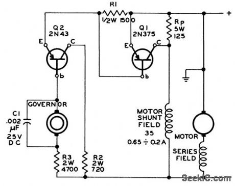
Centrifugal governor is used as error detector, with contacts handling only a few microwatts. Two-transistor amplifier actuated by governor is connected across motor field resistor, with power being obtained from 24 v d-c motor bus. Maintains 0.5-hp motor speed at 6,000 rpm over input voltage range of 20 to 30 v.-Transistorized Speed Regulator, Electronic Circuit Design Handbook, Mactier Pub. Corp., N.Y., 1965, p 30. (View)
View full Circuit Diagram | Comments | Reading(1258)
BALANCED_BRIDGE_REVERSING_DRIVE
Published:2009/7/22 2:00:00 Author:Jessie
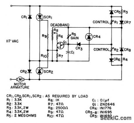
Phase-sensitive servo drive supplies reversible half-wave power to armature of small permanent magnet or to shunt motor. Power circuit consists of two half-wave circuits back-to-back (SCR1-CR1 and SCR2-CR2) fired by ujt Q1 on either positive or negative line half-cycle depending on direction of unbalance of reference bridge containing sensing element R1, which can be photoresistor, thermistor, potentiometer, or output from control amplifier.- Silicon Controlled Rectifier Manual, Third Edition, General Electric Co., 1964, p 142. (View)
View full Circuit Diagram | Comments | Reading(851)
ACCELERATION_SENSING_SWITCH_WITHOUTOVERSHOOT
Published:2009/7/22 1:59:00 Author:Jessie
Provides null capture in indicated balance point for each level of acceleration, with bidirectional current switching for accelerometer molar.-F. W. Kear, Dynamic Fluid Switch Senses Acceleration, Electronics,34:38,p 64-67. (View)
View full Circuit Diagram | Comments | Reading(807)
PUNCHED_TAPE_CONTROLS_MOTOR
Published:2009/7/22 1:58:00 Author:Jessie
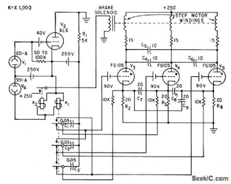
Photolubes sense holes punched in programmed tape and feed resulting command signals through relays to three thyratrons whose loads are windings of step motor for milling machine.-A. G. Thomas, Digital Control of Machine Tools, Electronics, 33:11, p 174-176. (View)
View full Circuit Diagram | Comments | Reading(761)
REVERSIBLE_HALF_WAVE_SPEED_CONTROL
Published:2009/7/22 1:57:00 Author:Jessie
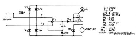
Simple circuit is adequate for majority of universal series-wound motor drive applications:Direction of ratation depends on which half-cycle scr conducts, since series fleld is in ac leg of bridge rectifier.- Silicon Controlled Rectifier Manual, Third Edition, General Electric Co., 1964, p 144. (View)
View full Circuit Diagram | Comments | Reading(992)
UNIVERSAL_MOTOR_SPEED_CONTROL
Published:2009/7/22 1:55:00 Author:Jessie
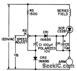
Regulated speed control is achieved by varying conduction angle of scr placed in series with armature and field of universal a-c/d-c motor. Makes use of motor residual field to induce counter emf in armature proportion to speed, +or use as feedback signal. Provides stable operation at low speeds for sewing machines and small appliances. - Silicon Controlled Rectifier Manual, Third Edition, General Electric Co., 1964, p 143. (View)
View full Circuit Diagram | Comments | Reading(0)
HALF_WAVE_DRIVE_FOR_D_C_MOTOR
Published:2009/7/22 1:54:00 Author:Jessie
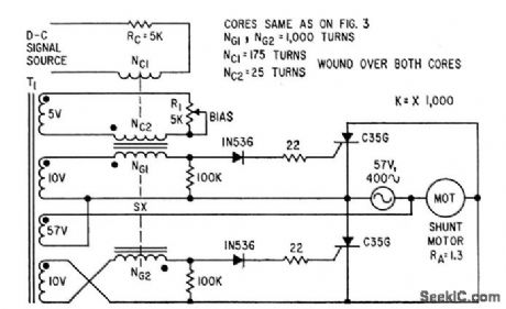
Uses controlled recliners to control armature of d-c shunt motor or d-c torquer, for applications requiring push-pull output for reversible drive. Saturable reactor control windings ore wound over both cores together. Maxi-mum current during reversal from top speed in one direction to top speed in opposite direction is approximately 20 amp, with cur rent dropping to 10 amp in 0.1 sec.-W. R. Seegmiller, Controlled Rectifiers Drive A-C and D-C Motors, Electronics, 32:46, p 73-75. (View)
View full Circuit Diagram | Comments | Reading(839)
ULTRASONIC_CONTROL_RECEIVER
Published:2009/7/22 1:54:00 Author:Jessie
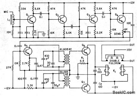
Five-stage amplifier Q1-5 amplifies both control signals, 38.285 kc and 41.805 kc, while Q6 and Q7 operate as class B detector-amplifiers to eliminate need for separate diode detectors. Desired control frequency energizes only one coil of double-fulcrum motor control relay. while noise acts on both coils and keeps relay balanced.-Transistor Amplifier Controls Remote Appliances, Electronics, 34:21, p 59.
(View)
View full Circuit Diagram | Comments | Reading(681)
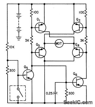
SMALL_D_C_MOTOR_CONTROL
Published:2009/7/22 1:53:00 Author:Jessie
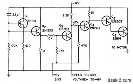
Will drive small permanent-magnet motor at speeds below 1rpm up to full speed, in direct proportion to control voltage, without friction problems. Applies full voltage of12 v to motor and provides speed regulation by interrupting voltage at about 50 cps and varying ratio of on time to off time.-Motor Speed Control, Electronic Circuit Design Handbook, Mactier Pub. Corp., N.Y., 1965, p 28. (View)
View full Circuit Diagram | Comments | Reading(779)
FULL_WAVE_REVERSING_D_C_MOTOR_DRIVE
Published:2009/7/22 1:52:00 Author:Jessie
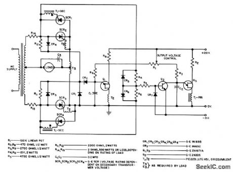
Designed around two scr's with common cathode (SCR2 and SCR3) and two more with common anodes (SCR1 and SCR4). If load is d-c motor, plugging action occurs if R1 is reversed suddenly. R14 and R15 limit fault current if voltage transient should ire odd or even-numbered pair simultaneously.- Silicon Controlled Rectifier Manual, Third Edition, General Electric Co., 1964, p 141. (View)
View full Circuit Diagram | Comments | Reading(733)
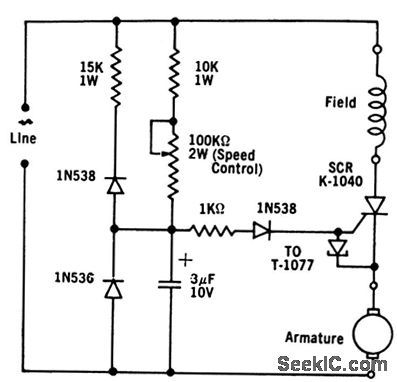
REVERSING_DRIVE_FOR_SERIES_D_C_MOTOR
Published:2009/7/22 2:09:00 Author:Jessie
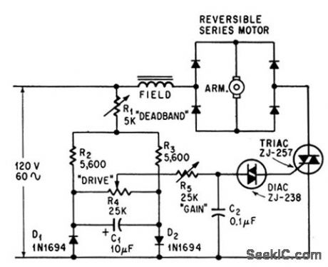
Triode and diode a-c switch Components can be triggered into conducting in either direction by applying positive or negative gate current signal.Transducers can be used in Place of Potentiometer and rheostats to give automatic speed control.-J. C. Hey, The Widening World of the SCR, Electronics,37:25,p 78-85. (View)
View full Circuit Diagram | Comments | Reading(700)
6_V_D_C_MOTOR
Published:2009/7/22 2:08:00 Author:Jessie
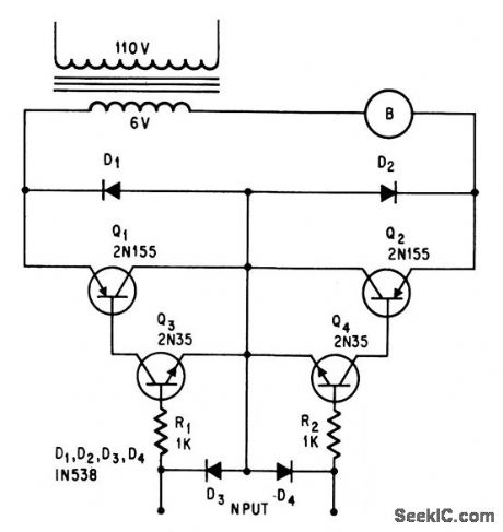
Motor B is energized by rectified voltage from transformer. Direction of rotation is controlled by polarity of input signal, which determines whether Q1 or Q2 is conducting. Motor draws several hundred ma.-J. B. Tiedemann, Transistors Control Small D-c Motor, Electronics, 39:7, p 93 (View)
View full Circuit Diagram | Comments | Reading(638)
MOTOR_NOISE_ACTUATES_MUTING_SYSTEM
Published:2009/7/22 2:07:00 Author:Jessie
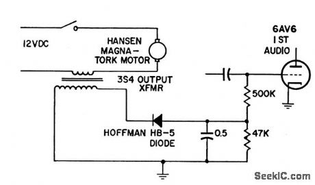
Noise pulses from commutator-type tuning motor in receiver ate rectified and used to bias audio stage to cutoff for as long as tuning motor is running. Audio amplifier re mains cut off for about 0.25 sec after motor stops.-Muting System for Motor-Tuned Receivers, Electronic Circuit Design Handbook, Mactier Pub. Corp, N.Y. 1965, p 51. (View)
View full Circuit Diagram | Comments | Reading(776)
SPEED_FEEDBACK
Published:2009/7/22 2:07:00 Author:Jessie
Introduction of speed feed-back signal into firing circuit helps maintain constant torque regardless of speed. Tunnel diodes provide excellent stabilizing action at tow speeds.-TD/SDR Combos for Sale, EEE, 12:3, p 62-64. (View)
View full Circuit Diagram | Comments | Reading(900)
FIELD_EFFECT_TRANSISTOR_CONTROLS_PULSE_OSCILLATOR
Published:2009/7/22 2:05:00 Author:Jessie
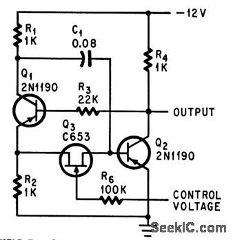
C653 transistor serves as voltage-controlled nonlinear resistor that varies time constant of oscillator. Can generate narrow output pulses at rates up to several Mc, to drive stepping motor.-T. C. Ross, Field-effect transistor Controls Pulse Oscillator, Electronics, 37:18, p 80-81. (View)
View full Circuit Diagram | Comments | Reading(741)
THREE_SPEED_BLENDER_CONTROL
Published:2009/7/22 2:05:00 Author:Jessie
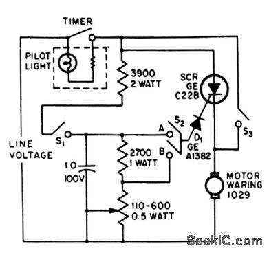
Single scr safely handles 7.5-amp current of 1/2-hp motor. Feedback is used to change firing angle of scr as load increases, to maintain constant blending speed.-J. Eimbinder, SCRs In The Consumer Market, FEE, 14:8, p 100-103. (View)
View full Circuit Diagram | Comments | Reading(1946)
STEPPER_MOTOR__PULSE__GENERATOR
Published:2009/7/22 2:03:00 Author:Jessie
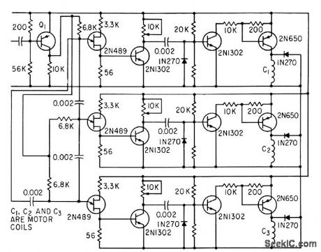
Unijunction ring counter energizes winding of stepper motor sequentially,-F.W. Kear, Digital Control Uses Unijunction Transistors, Electronics, 34:18, p 79-80. (View)
View full Circuit Diagram | Comments | Reading(844)
Nonzero_crossing_optically_isolated_triac_drivers
Published:2009/7/22 2:25:00 Author:Jessie
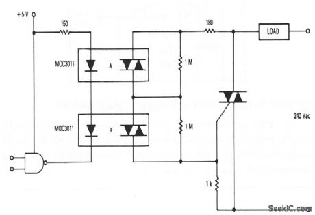
This circuit shows two MOC3011 optoisolators used to drive a 240-V triac-controlled load-even though the individual MOC3011 voltage rating is not sufficiently high to be used directly on a 240-V line. The two 1-MΩ resistors equalize the voltage on the MOC3011s. (View)
View full Circuit Diagram | Comments | Reading(722)
Full_wave_thyristor_control_with_average_voltage_feedback
Published:2009/7/22 2:23:00 Author:Jessie
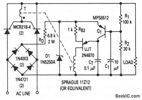
This circuit shows a UJT that is used as a thyristor rigger (with feedback), where the average full-wave load voltage is the desired feedback variable. Notice that the line voltage is first rectified. R1, R2, and C1 average the load voltage so that the voltage can be compared with the rectified line voltage. (View)
View full Circuit Diagram | Comments | Reading(755)
Simple_time_delay
Published:2009/7/22 3:25:00 Author:Jessie
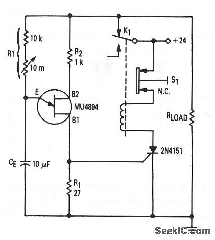
This circuit shows the basic UJT building block (Fig. 9-1) that is used to provide a simple time-delay function. When normally closed S1 is pushed, the SCR turns off, K1 is de-energized, and power is applied to the UJT relaxation oscillator and load. After a time delay that varys from less than 1 s to about 2.5 min.(as determined by the setting of the 1-MΩ pot), the UJT fires and turns on the SCR. K1 is energized and power is removed from the UJT and load. K1 stays energized until S1 is pushed again. (View)
View full Circuit Diagram | Comments | Reading(0)
| Pages:137/312 At 20121122123124125126127128129130131132133134135136137138139140Under 20 |
Circuit Categories
power supply circuit
Amplifier Circuit
Basic Circuit
LED and Light Circuit
Sensor Circuit
Signal Processing
Electrical Equipment Circuit
Control Circuit
Remote Control Circuit
A/D-D/A Converter Circuit
Audio Circuit
Measuring and Test Circuit
Communication Circuit
Computer-Related Circuit
555 Circuit
Automotive Circuit
Repairing Circuit