
Control Circuit
Index 133
Overvoltage_protection_for_telephone_equipment
Published:2009/7/21 22:31:00 Author:Jessie
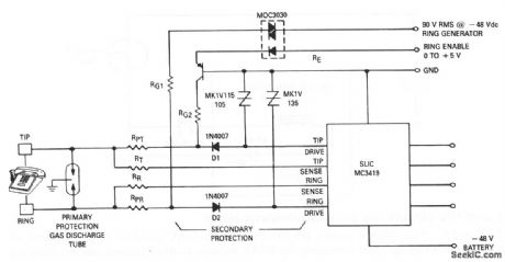
This circuit shows two SIDACs that are connected to protect the telephone Subscriber Loop Interface Circuit (SLIC) and associated electronics from voltage surges. This is in addition to the primary protection provided by the gas-discharge tube across the tip and ring lines. If a high positive-voltage transient appears on the lines, D1 (with a peak-inverse voltage of 1000 V) blocks the pulse, and the corresponding SIDAC conducts the surge to ground. Conversely, D2 and the related SIDAC protect the SLIC from negative transients. The SIDACs do not conduct when normal signals are present. (View)
View full Circuit Diagram | Comments | Reading(1976)
SIDEBAND_SELECTOR_MOSFET
Published:2009/7/21 22:44:00 Author:Jessie
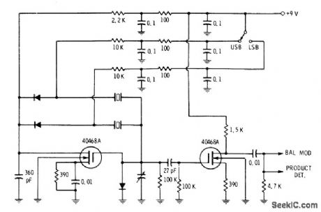
circuit uses diode switching of crystals in carrier oscillator to select either upper or lower sideband. Second transistor serves as common-source isolating amplifier for driving modulator. Switch applies +9V to anode of diode that closes feedback circuit for crystal to be activated. Developed for use in SSB transceiver; if operating in 9-MHz range, crystals can be 8.9985 MHz and 9.0015 MHz.-E. M. Noll, FET Principles, Experiments, and Projects, Howard W. Sams, Indianapolis, IN, 2nd Ed., 1975, p 191-192. (View)
View full Circuit Diagram | Comments | Reading(1018)
Time_delay_circuit_using_a_UJT_and_two_SCRs
Published:2009/7/21 22:41:00 Author:Jessie
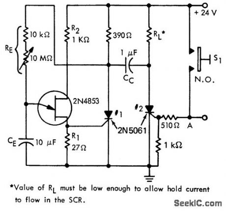
Time delay circuit using a UJT and two SCRs. Time delay is determined by setting of 10M pot from less than a second to approximately 2.5 minutes (courtesy Motorola Semiconductor Products Inc.). (View)
View full Circuit Diagram | Comments | Reading(966)
Motor_speed_control_with_load_current_feedbac
Published:2009/7/21 22:41:00 Author:Jessie
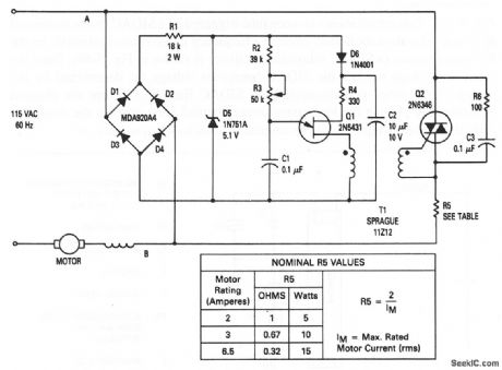
This circuit shows a triac motor-speed control that derives feedback from the load current and does not require separate connections to the motor field and armature windings. Thus, this circuit can be conveniently built into an appliance or used as a separate control, When the triac conducts, in response to signals from Q1 through T1, the normal line voltage (less the drop across the triac and R5) is applied to the motor. By delaying the firing of the triac until a later portion of the cycle, the voltage applied to the motor is reduced (or controlled) and speed is reduced proportionally. The use of feedback maintains torque at reduced speeds. The angle at which Q1 fires is proportional to motor current (and the setting of R3) because Q1 is controlled by the voltage across points A and B. As the motor is loaded and draws more current, the firing angle of Q1 is advanced, causing a proportional increase in the voltage applied to the motor, and a consequent increase in the available torque. (View)
View full Circuit Diagram | Comments | Reading(5476)
LOGARITHMIC_LIMITER
Published:2009/7/21 22:38:00 Author:Jessie
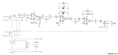
Speech processor with logarithmic limiting makes noticeable improvement in speech readability of SSB transmitter. Adjustable-gain preamp U1 sets input level for soft limiting amplifier U2 in which nonlinear resistance characteristics of CR1 and CR2 supply increasingly heavier negative feedback as U2 output amplitude increases, thus providing logarithmic response. Low-pass active filter using U3 attenuates any frequencies above 2.8 kHz that may be generated in clipping process.-F. C. Getz, Audio-Frequency Speech Processor, Ham Radio, Aug. 1977, p 48-51. (View)
View full Circuit Diagram | Comments | Reading(1410)
24_hour_clock_without_the_1_hertz_reference_circuitry
Published:2009/7/21 22:37:00 Author:Jessie
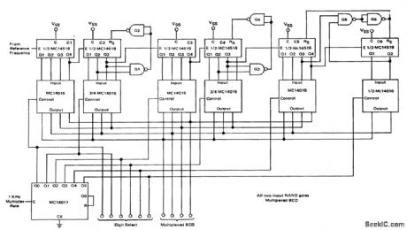
24-hour clock without the 1-hertz reference circuitry. It provides seconds, minutes and hours (courtesy Motorola Semiconductor Products Inc.). (View)
View full Circuit Diagram | Comments | Reading(1432)
TAPE_LOOP_SPEED_CONTROL
Published:2009/7/7 0:01:00 Author:May
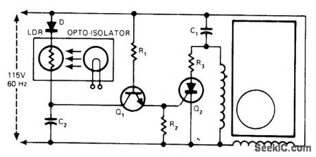
Shunt rectifier-capacitor circuit was developed for speed control of permanent split-capacitor fractional-horsepower induction motor used in some motion-picture projectors. Light-dependent resistor UDR makes Q2 conduct when light from lamp is not blocked by tape loop. Split capacitor C1 for motor provides both run and speed-control functions without switching. Values are: C2 0.01μF; D 1N4004; Q1 2N4987; Q2 C106B; R1 330K; R2 100; R3 10.-T. A. Gross, Control the Speed of Small Induction Motors, EDN Magazine, Aug. 20, 1977, p 141-142. (View)
View full Circuit Diagram | Comments | Reading(1682)
2_hp_THYRISTOR_CONTROL
Published:2009/7/6 23:57:00 Author:May
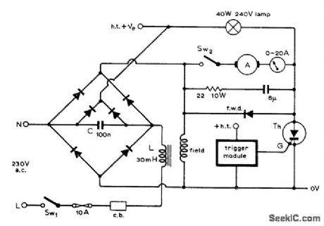
Provides smooth variation in speed of shunt-wound DC motor from standstill to 90% of rated speed. Use thyristor rated 30 A at 600 V. Outer diodes of bridge are 35-A 600-PIV silicon power diodes, as also is thyristor diode, and inner diodes are 5-A 600-V silicon power diodes. Article gives complete circuit of trigger pulse generator used to control speed by varying duty cycle of thyristor. Larger motors can be controlled similarly by uprating thyristor and diodes. Controller will also handle other types of loads, including lamps and heaters.-F. Butler, Thyristor Control of Shunt-Wound D.C. Motors, Wireless World, Sept. 1974, p 325-328. (View)
View full Circuit Diagram | Comments | Reading(1658)
MOSFET_PRODUCT_DETECTOR
Published:2009/7/21 22:34:00 Author:Jessie

SSB IF signal is applied to one gate of MOSFET and demodulating carrier to other gate. Linear demodulation is obtained without distortion components. RC filter connected into drain circuit removes IF and carrier components, leaving de-modulated audio as output.-E. M. Noll, FET Principles, Experiments, and Projects, Howard W. Sams, Indianapolis, IN, 2nd Ed., 1975, p 154. (View)
View full Circuit Diagram | Comments | Reading(1121)
PWM_SPEED_CONTROL
Published:2009/7/6 23:53:00 Author:May
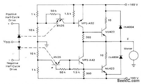
Power stage using Motorola 4N26 optoisolators and push-pull transistors drives fractional -horsepower single-phase AC motor over speed range of 5% to 100% of base speed. Input drives are provided by pulse-width modulation inverter using stored program in ROM to generate sine-weighted pulse trains to provide variable-frequency drive.-T. Mazur, ”ROM-Digital Approach to PWM-Type Speed Control of AC Motors,”Motorola, Phoenix, AZ, 1974, AN-733, p12. (View)
View full Circuit Diagram | Comments | Reading(2962)
SWITCHING_MODE_CONTROLLER
Published:2009/7/6 23:49:00 Author:May
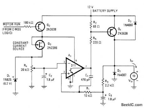
Developed for driving 0.0l-hp motor M at variable speeds with minimum battery drain. Circuit uses pulses with low duty cycle to set up continuous current in motor approximating almost 200 mA when average battery drain is 100 mA for output volt-age of 3.5 V. Voltage comparator A, serves as oscillator and as duty-cycle element of controller. C1 and R1 provide positive feedback giving oscillation at about 20 kHz, with duty-cycle range of 10% to 70% controlled by feedback loop Q1-R1-C3-R3. D2 is used in place of costly large capacitor for filtering.-J. C. Sinnett, Switching-Mode Controller Boosts DC Motor Efficiency, Electronics, May 25, 1978, p 132. (View)
View full Circuit Diagram | Comments | Reading(737)
10_MHz_PRODUCT_DETECTOR
Published:2009/7/21 23:13:00 Author:Jessie
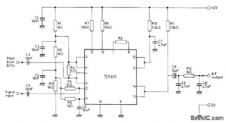
IF signal of SSB receiver is mixed with signal from beat-frequency oscillator in Mullard TCA240 dual balanced modulator-demodulator to give desired audio output signal, Simple low-pass filter R12-C9-C10 removes unwanted output signal.- Applications of the TCA240, Mullard, London, 1975, Technical Note 18, TP1489. (View)
View full Circuit Diagram | Comments | Reading(2589)
SINGLE_SUPPLY_PRODUCT_DETECTOR
Published:2009/7/21 23:11:00 Author:Jessie
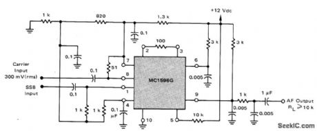
Motorola MC1596G balanced modulator requires no carrier null adjustment because all frequencies except desired demodulated audio are in RF spectrum and easily filtered out. Circuit performs well with carrier input levels of 100-500mVRMS. Provides good product detector performance from very low frequencies up to 100MHz.-R Hejhall, MC1596 Balanced Modulator,Motorola.Phoenix.AZ,1975.AN-531,p7. (View)
View full Circuit Diagram | Comments | Reading(834)
UNTUNED_DOUBLE_BALANCED_MIXER
Published:2009/7/21 23:10:00 Author:Jessie
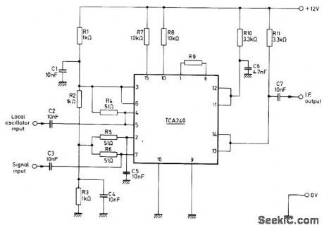
Wideband mixer for high-frequency SSB circuits operates from single 12-V supply. Gain is controlled by R9 and increases as value of R9 is decreased. Output at pins 13 and 14 is product of local oscillator and signal input frequencies and contains desired IF value for receiver. Oscillator signal level should be kept below 20 mV to avoid undesired harmonics produced by limiting. Circuit uses Mullard TCA240 dual balanced modulator-demodulator.- Applications of the TCA240, Mullard, London, 1975, Technical Note 18, TP1489. (View)
View full Circuit Diagram | Comments | Reading(1181)
TWO_TONE_TESTER
Published:2009/7/21 23:09:00 Author:Jessie
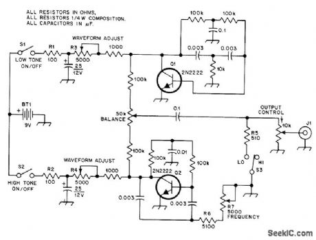
Twin-T transistor oscillators generate two distinct sine-wave AF signals for use in adjusting SSB transmitters. Q1 is fixed at about 1000 Hz, and Q2 is adjustable between 1000 and 1300 Hz, giving frequency difference of 0-300 Hz for use with scopes having 60-Hz horizontal sweep rate that permits display of one to five cycles of RF envelope pat-tern. Switches permit use of either oscillator separately.-F. Brown, The Two-Tone Tester, QST, Nov, 1978, p 22-24. (View)
View full Circuit Diagram | Comments | Reading(1349)
RING_MODULATOR
Published:2009/7/22 1:08:00 Author:Jessie
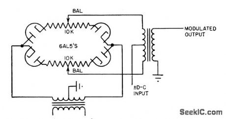
Can be operated with either input or output ungrounded. With 100-v rms carrier and d-c input of 30 v, output is linear up to 0.2 v rms. Null level is less than 1 mv, but drift stability is poor and balance is critical. Used in applications where modulation of error signal is re quired.-L. S. Klivans, Modulators for Automatic Control Systems, Electronics, 31:1, p 82-84. (View)
View full Circuit Diagram | Comments | Reading(830)
VARIABLE_TONE_USING_VCO
Published:2009/7/22 Author:Jessie
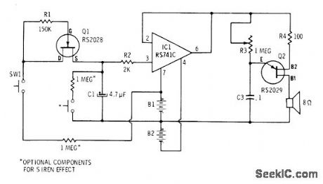
Tone generator uses UJT and opamp in voltage-controlled oscillator Frequency of audio output is determined by setting of R3 For two-tone siren effects, optioal switches and resistors can be used, To speed up siren effect, use smaller value for C1.-F.M Mims, Integrated Circuit Projects,vol.4, Radio Shack, Fort Worth,TX,1977,2nd Ed.p61-69. (View)
View full Circuit Diagram | Comments | Reading(933)
Precision_frequency_counter_tachometer
Published:2009/7/21 23:59:00 Author:Jessie

Precision frequency counter/tachometer. The ICM7207A provides a 1-second gating window and the store and reset signals. The display reads hertz directly. With pin 11 of the ICM7207A connected to V+ the gating time will be 0. 1 second, which gives tens of hertz in the LSB position. For shorter gating times a 6.5536 MHz crystal may be used, giving a 0.01-second gating with pin 11 connected to V+ and a 0.1-second gating with pin 11 open. To implement the 4-digit tachometer the ICM7207A with a 1-second gating should be used. In order to get the display to read directly in RPM the rotational frequency must be multiplied by 60.This can be done electronically using a PLL or mechanically using a disc rotating with the object with appropriate hole drilled for light from an LED to a photodevice (courtesy Intersil, Inc.). (View)
View full Circuit Diagram | Comments | Reading(0)
WHOOPER
Published:2009/7/21 23:59:00 Author:Jessie
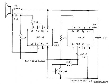
Two National LM3909 ICs and single transistor generate rapidly modulated tone resembling that used on some police cars, ambulances, and airport emergency vehicles. Rapidly rising and falling modulating voltage is generated by IC having 400-μF capacitor. Diode-connected transistor forces this IC ramp generator to have ranger ON periods than OFF periods, raising average tone of tone generator and making modulations seem more even.- Linear Applications, Vol. 2, National Semiconductor, Santa Clara, CA, 1976, AN-154, p 7. (View)
View full Circuit Diagram | Comments | Reading(0)
100_MHz_frequency_and_period_counter_using_the_Intersil_ICM7226B_40_pin_DIP
Published:2009/7/21 23:31:00 Author:Jessie
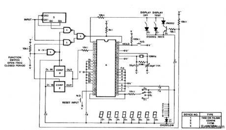
100 MHz frequency and period counter using the Intersil ICM7226B 40-pin DIP. This circuit uses a CD4016 analog multiplexor to multiplex the digital outputs back to the function input. Since the CD4016 is a digitally controlled analog transmission gate no level shifting of the digital output is required. CD4051s or CD4052s could also be used to select the proper inputs for the multiplexed input on the ICM7226 from 2-or 3-bit digital inputs. These analog multiplexers could also be used in systems in which the mode of operation is controlled by a microprocessor rather than directly by front panel switches (courtesy Intersil, Inc.). (View)
View full Circuit Diagram | Comments | Reading(2673)
| Pages:133/312 At 20121122123124125126127128129130131132133134135136137138139140Under 20 |
Circuit Categories
power supply circuit
Amplifier Circuit
Basic Circuit
LED and Light Circuit
Sensor Circuit
Signal Processing
Electrical Equipment Circuit
Control Circuit
Remote Control Circuit
A/D-D/A Converter Circuit
Audio Circuit
Measuring and Test Circuit
Communication Circuit
Computer-Related Circuit
555 Circuit
Automotive Circuit
Repairing Circuit