
Control Circuit
Index 129
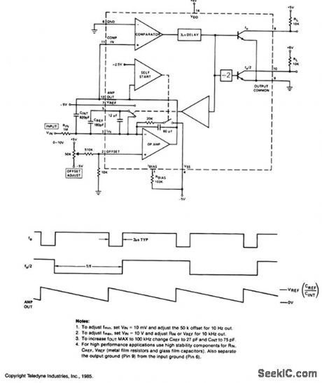
10_Hz_TO_10kHz_V_F_CONVERTER
Published:2009/7/7 4:20:00 Author:May
View full Circuit Diagram | Comments | Reading(658)
HIGH_LEVEL_CMOS_CONTROL
Published:2009/7/7 4:14:00 Author:May
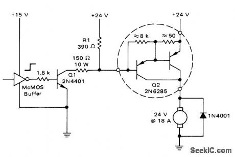
When output of CMOS buffer goes high, Q1 turns on and sinks 150-mA base current of power Darlington Q2, to activate motor load. Used in logic-controlled industrial applications.-A. Pshaenich, Interface Techniques Between Industrial Logic and Power Devices, Motorola, Phoenix, AZ, 1975, AN-712A, p 18. (View)
View full Circuit Diagram | Comments | Reading(810)
HARNESS_TESTER_USES_NEON_FLIP_FLOPS
Published:2009/7/21 22:01:00 Author:Jessie
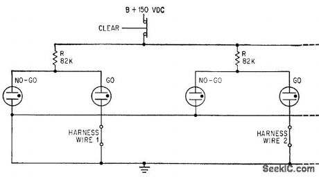
One end of each harness wire under lest is grounded. Other end completes circuit for GO glow lamp. Discontinuity in wire opens GO cathode, decreases voltage drop through R, and makes NO-GO lamp glow.-Harness Tester Detects and Indicates Intermittent Faults, Electronics, 37:4, p 56-57. (View)
View full Circuit Diagram | Comments | Reading(570)
3_30_MHz_QUADRATURE_PHASE_SHIFT
Published:2009/7/21 22:00:00 Author:Jessie
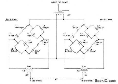
Wide-band passive AF phaseshift network makes direct-conversion SSB generation possible Bridge networks each provide 45°phase shift, to give differential phase shift of 90°over entire frequency range with maximum phase error of about 1° Overall loss of network is about 6 dB,T1,T2,and T3 are wound on Neosid 1050-1-F14 of Indiana General F684-1 balun core. Twist together three 7-inch lengths of No. 26 enamel and wind 3 turns through the two holes. Connect two wires in series for 200-ohm windings. Article gives data for winding all other coils.-R. Harrison, A Review of SSB Phasing Teqhniques, Ham Radio, Jan. 1978, p 52-62. (View)
View full Circuit Diagram | Comments | Reading(1833)
NUCLEAR_RESONANCE_SENSOR
Published:2009/7/21 21:36:00 Author:Jessie
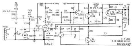
Temperature telemeter depends on absorption of r-f energy by chlorine molecule in proportion to temperature. When spectrometer oscillator V1 is tuned to frequency of correct absorption line, each oscillator pulse sets up oscillations in probe that last long enough to affect starting voltage for next oscillator pulse. After plate detection and low-pass filtering to suppress quench frequency, signal goes to two-stage a-f amplifier Q1-Q2, whose output to cro indicates whether spectrometer is on nuclear resonance frequency.-C. Dean, Using Nuclear Resonance to Sense Temperature, 33:28, Electronics, p 52-54. (View)
View full Circuit Diagram | Comments | Reading(669)
TEMPERATURE_DRIFT_CONTROL
Published:2009/7/21 21:34:00 Author:Jessie
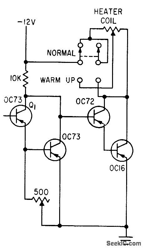
Used to minimize thermal drift in d-c amplifer. Temperature-sensing element Q1 controls current through heater of temperature-controlled block. Base of Q1 is left floating. Variations in ambient temperature are reduced by factor of 10 inside block, and transistors are maintained at 40℃.-A. Patton, Telemetry System for Testing Automobiles, Electronics, 33:43, p 57-59. (View)
View full Circuit Diagram | Comments | Reading(767)
CONTROL_CIRCUIT_FOR_PHOTOFEEDBACK_PYROMETER
Published:2009/7/21 21:33:00 Author:Jessie
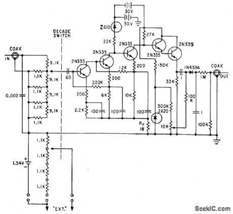
Decade amplifer of conventional phototransistor pyrometer control was modifed by removing output transformer and load inductor, lo give additional feed-back at low frequencies. Bootstrap emitter. follower stage was added as output buffer to improve circuit stability. Used for measuring high rocket surface temperatures.-S. A. Edler, Designing Phototransistor Pyrometers With and Without Feedback, Electronics, 34:49, p 56-60. (View)
View full Circuit Diagram | Comments | Reading(939)
SIDEBAND_MIXER
Published:2009/7/21 21:32:00 Author:Jessie
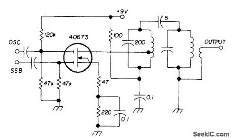
Used as transmitting mixer in SSB transceiver made by Sideband Associates for radiomarine communication in 2-23 MHz range. Low-frequency sideband signal and high-frequency oscillator signal are mixed to produce higher sum frequency at output.Double-tuned resonant circuit provides adequate output bandwidth and excellent skirt rejection of undesired frequency components.-E. Noll, MOSFET Circuits, Ham Radio, Feb. 1975, p 50-57. (View)
View full Circuit Diagram | Comments | Reading(873)
OVER_UNDER_TEMPERATURE_MONITOR
Published:2009/7/21 21:30:00 Author:Jessie
Dual output can be used to drive high and low temperature indicator lamps or relays. Balanced bridge may also be used to trigger conventional scrload combinations.- Silicon Controlled Rectifier Manual, Third Edition, General Electric Co., 1964, p 120. (View)
View full Circuit Diagram | Comments | Reading(777)
OFF_AIR_MONITOR
Published:2009/7/21 21:29:00 Author:Jessie
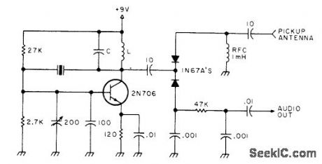
Single-frequency modulation monitor for SSB transmitter combines crystal oscillator with product detector, for checking audio at one point within band. If tuning and loading of SSB transmitter are same over rest of band, audio quality also remains constant. Use fundamental-mode crystal for desired band. LC circuit should be resonated to band being used. Oscillator signal is spotted with transceiver in receive mode, after which transceiver can be monitored during transmissions.-Clean Up Your Act, 73 Magazine, Jan.1978, p 136-137. (View)
View full Circuit Diagram | Comments | Reading(1255)
PULSED_BRAKE
Published:2009/7/7 4:02:00 Author:May
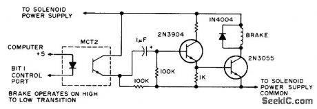
Transition from high (1) to Dow (0) at control port of microprocessor energizes brake solenoid of paper-tape, reader in pulses lasting several microseconds, with time determined by size of capacitor used. Energizing of solenoid squeezes tape between top of solenoid and flat iron brake shoe that is attracted by solenoid. Unmarked resistor is 1K.-D. Hogg, The Paper Taper Caper, Kilobaud, March 1977, p 34-40. (View)
View full Circuit Diagram | Comments | Reading(2492)
HYBRID_THERMOSTAT
Published:2009/7/21 20:33:00 Author:Jessie
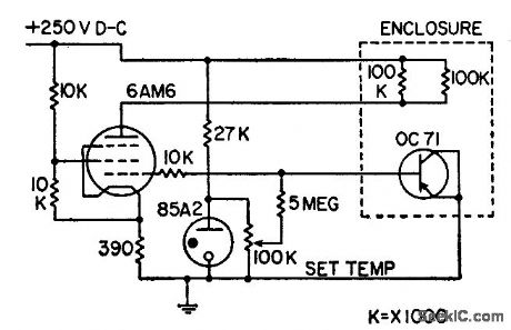
Utilizes reverse characteristics of pnp junctions for temperature control. Provides continuous control with higher sensitivity than thermistors, along with quiet operation, remote resetting of temperature, and small thermal time constant. Chief disadvantage is high impedance.-H. Sutcliffe, Transistor Temperature Controller, Electronics, 31:13, p 81-84. (View)
View full Circuit Diagram | Comments | Reading(823)
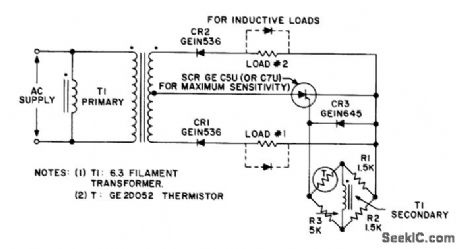
THERMISTOR_IS_SENSOR_FOR_OVEN_CONTROL
Published:2009/7/21 20:31:00 Author:Jessie
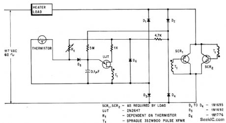
When oven temperature drops, thermistor resistance increases, making unijunction transistor trigger earlier in line voltage cycle so scr's deliver more power to oven. -J. C. Hey, The Widening World of the SCR, Electronics, 37:25, p 78-85. (View)
View full Circuit Diagram | Comments | Reading(955)
SCHMITT_TRIGGER_AS_TIME_PROPORTIONING_TEMPERATURE_CONTROL
Published:2009/7/21 20:30:00 Author:Jessie
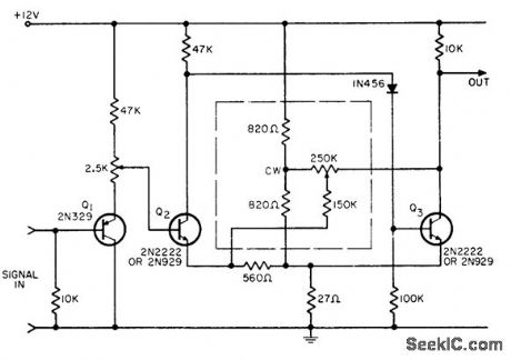
Hysteresis of Schmitt trigger (difference between turn-on und turnoff signal levels) is adjusted with negative feedback instead of positive, lo reduce hysteresis to less than 1 my. Trigger point can be adjusted above or below ground reference despite use of only one power supply. Modification of negative feedback causes dutycycle-controllable oscillation. Potentiometer adjusts circuit gain smoothly over wide range. -P. Lefferts, 'Super' Schmitt Uses Negative Feedback, EEE, 12:12, p 52-53. (View)
View full Circuit Diagram | Comments | Reading(1060)
SHORT_CIRCUIT_PROTECTION
Published:2009/7/21 11:06:00 Author:Jessie
Voltage-sensing short-circuit switch Q4-Q5 turns off series-regulating tronsistor Q1 when load R1 is short-circuited.-G. A. Chunn and G. D. Norton, Short-Circuit Protection Consumes Little Power, Electronics, 38:22, p 68. (View)
View full Circuit Diagram | Comments | Reading(0)
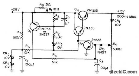
SERIES_REGULATOR_WITH_CAPACITIVE_OVER_LOAD_PROTECTION
Published:2009/7/21 11:04:00 Author:Jessie
R-C delaying network in dotted box applies drive slowly to series. pass transistor to prevent overload protective circuit from turning off regulator when surge current charges capacitive load. Network does not reduce response time.-J. Takesuye and H. Weber, Silicon Power Transistors Provide New Solutions to Voltage Control Problems, Motorola Application Note AN-163, Aug. 1964. (View)
View full Circuit Diagram | Comments | Reading(745)
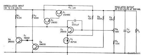
REDUCED_POWER_OVERLOAD_PROTECTION_
Published:2009/7/21 11:02:00 Author:Jessie
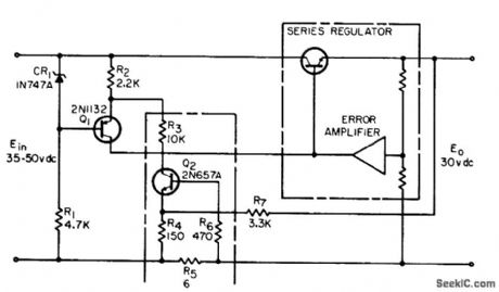
Circuit reduces power dissipotion in series regulator transistors under overload or short-circuit conditions by making output current decrease as load resistance decreases. Values shown are for 30 V d-c supply delivering 0.25 amp, with current limiting starting at 0.31 amp.-R. A. Lewis, Reduced-Power Overload Protection, EEE, 12:11, p 67. (View)
View full Circuit Diagram | Comments | Reading(797)
ADJUSTABLE_OVERLOAD_TRIP
Published:2009/7/21 11:01:00 Author:Jessie
Protection circuit, added to conventional regulator, consists of R1, R2, R3, R4, C2, CR2, CR3, and Q1. When load current reaches preset trip level, drop across R1 tums on Q1, which in turn saturates Q2 ond cuts off regulator transistor Q3-Q4 to protect these transistors and reduce output voltage to zero. Turnoff is regenerative, hence fast. To reset, supply voltage is switched off and then back on.-W. A. O'Berry, Adjustable Overload Protection, EEE, 12:2, p 29. (View)
View full Circuit Diagram | Comments | Reading(745)
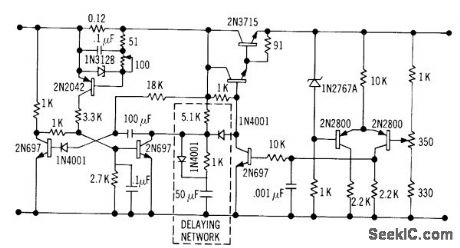
SHORT_PROOF_REGULATOR
Published:2009/7/21 11:00:00 Author:Jessie
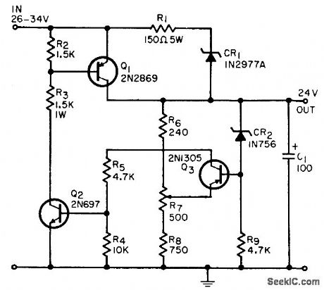
Provides constant 24 V at up to 500 ma and turns itself off when load is shorted. Restarts automatically when short is removed. Regulation is within 1% from no load to 500 ma and with input voltages from 26 to 34 V.-D. E. Wilson, Inexpensive Short-Proof Voltage Regulator, EEE, 12:6, p 64. (View)
View full Circuit Diagram | Comments | Reading(771)
TIMER_WITH_ALARM_
Published:2009/7/7 3:58:00 Author:May
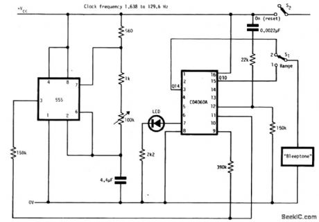
The circuit has two ranges: secs to 5 mins and 1 min to 80 mins.It can be powered by a 9-V battery.With the LED connected as shown a reasonable frequency of flashing occurs throughout the range of operation.This circuit is reset when S2 is closed. (View)
View full Circuit Diagram | Comments | Reading(887)
| Pages:129/312 At 20121122123124125126127128129130131132133134135136137138139140Under 20 |
Circuit Categories
power supply circuit
Amplifier Circuit
Basic Circuit
LED and Light Circuit
Sensor Circuit
Signal Processing
Electrical Equipment Circuit
Control Circuit
Remote Control Circuit
A/D-D/A Converter Circuit
Audio Circuit
Measuring and Test Circuit
Communication Circuit
Computer-Related Circuit
555 Circuit
Automotive Circuit
Repairing Circuit