
Control Circuit
Index 141
Using MAX1298/1299 To Make Up Temperature/Voltage Monitoring System Circuit
Published:2011/8/1 10:52:00 Author:Robert | Keyword: Temperature, Voltage, Monitoring, System
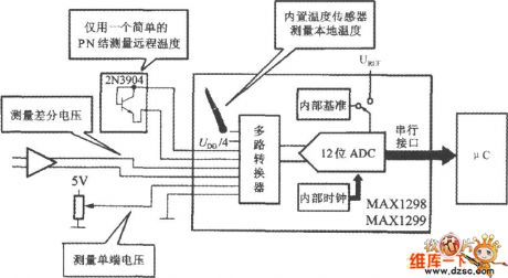
As shown in the picture. This system uses the internal temperature sensor to measure the room temperature. And it uses a 2N3904 type transistor's emitter polar to measure the remote temperature. Other input channels are used to measure the differencial voltage and 0~+5V single-port voltage. The MAX1298/1299 is connected to the uC through the serial interfaces. (View)
View full Circuit Diagram | Comments | Reading(565)
Celsius Temperature And Temperature Difference Measuring Circuit
Published:2011/7/26 21:21:00 Author:Robert | Keyword: Celsius, Temperature, Difference, Measuring
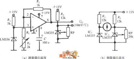
The LM135 series is based on the thermodynamic temperature calibration. If wanting to measure the celsius temperature (t) and celsius temperature difference (△t), it could use the circuits shown in picture (a) and (b). The picture (a)'s circuit's output port is connected to digital voltage meter and it would display the celsius temperature value. The picture (b)'s circuit is used to indicate the temperature difference by using galvanometer. (View)
View full Circuit Diagram | Comments | Reading(814)
FIELD_DISTURBANCE_SENSOR_ALARM
Published:2009/7/5 23:12:00 Author:May
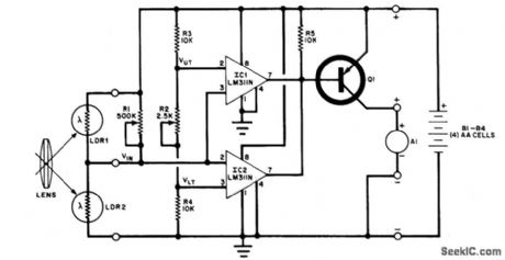
Circuit NotesThe changein ambient light triggers the alarm by changing resistance of LDR1 and LDR2, Q1=Radio Shack 276-2024 A1=Mallory SC628P Sonalert LDR1,LDR2=Cadmium sulfide photoce⒒,Radio Shack 276-116 (View)
View full Circuit Diagram | Comments | Reading(981)
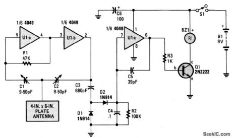
PROXIMITY_ALARM
Published:2009/7/5 23:08:00 Author:May
Circuit Notes
Inverters U1a and U1b are connected in a simple RC oscillator circuit. The frequency is determined by the values of R1, C1, C2, and the intemal characteristics of the integrated circuit. As long as, the circuit is oscillating, a positive dc voltage is developed at the output of the voltage-coupler circuit: C3, D1, D2 and C4. The dc voltage is applied to the input of Ulc-the third inverter amplifier-keeping its output in a low state, which keeps Q1 turned off so that no sound is produced by BZ1. With C1 and C2 adjusted to the most sensitive point, the pickup plate will detect a hand 3 to 5-inches away and sound an alert.Set C1 and C2 to approximately one-half of their maximum value and apply power to the circuit. The circuit should oscillate and no sound should be heard. Using a non-metallic screwdriver, carefully adjust C1 and C2, one at a time, to a lower value until the circuit just ceases oscillation: Buzzer BZ1 should sound off. Back off either C1 or C2 just a smidgen until the oscillator starts up again-that is the most sensitive setting of the circuit. (View)
View full Circuit Diagram | Comments | Reading(0)
FET_DUAL_TRACE_SCOPE_SWITCH
Published:2009/7/5 23:04:00 Author:May
The switcher output goes to the single vertical input of the scope,and a sync line from one of the Inputs is taken to the scope's external-Sync Input.Frequency response of the input amplifiers is 300 kHz over the range of the gain controls.With the gain controls wide open so no attenuatjon of the signal takes place,the frequency response is up to 1 MHz (View)
View full Circuit Diagram | Comments | Reading(1177)
ZENER_CONTROLS_BRIDGE
Published:2009/7/5 23:00:00 Author:May
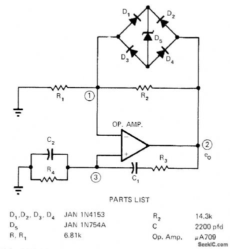
Amplitude of 10.5-kHz Wien-bridge oscillator outputis main-tained symmetrical above ground by using single zener with diode bridge,As output e0 approaches soft knee threshold of conduction for zener.its impedance decreases and shunts R2,This violates oscillator requirement that R2=2R1. so output begins decreasing sinusoidally. As swing decreases, gain increases until e0 reaches negative threshold. Signal then reverses and again starts going positive.-W. B Crittenden and E. J. Owings, Jr., Zener-Diode Controls Wien-Bridge Oscillator, EDN Magazine. Aug. 1. 1972. p 57-58. (View)
View full Circuit Diagram | Comments | Reading(1386)
Electric Blanket And Rice Cooker Timer Circuit
Published:2011/7/28 6:55:00 Author:Robert | Keyword: Electric Blanket, Rice Cooker, Timer
The picture shows the electric blanket and rice cooker timer circuit. This circuit's timing time could be set from 1 second to more than 10 hours. In the picture, C1 is timing element. When the power supply is connected, pressing the switch AN1, the C1 would be charging to DC 28V. The comparator A would output high voltage level and the transistor VT would be connected, the relay J would be powered up and have actions. The J1-1 would be conncted and the power would be self-locked. The J1-2 would be disconnected. C1 would discharge to the high-resistance input port. When the C1's voltage is decreased and lower than the A's out-phase input port, the A would output low voltage level, the transistor VT would be disconnected, J would lost the power and be released. Then the timing is over until next case that the timing trigger switch AN1 is pressed again. (View)
View full Circuit Diagram | Comments | Reading(3120)
Power Supply Protection Circuit of TL431
Published:2011/7/24 7:11:00 Author:Michel | Keyword: Power Supply, Protection Circuit
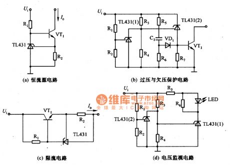
The a,b,c,d are power supply protection circuits of TL431.The picture (a) is constant current circuit of TL431 and the constant current I。=UREF/R2.Picture (b) is protection circuit of overvoltage and undervoltage and the voltage is equal to (1+R3/R4)UREF+UBE,when it is under voltage,the voltage is equal to (1+R1/R2)UREF when it is overvoltage.In the formula,UBE is the base-emiting voltage of VT1.Picture (c) is the current-limiting circuit and the limitting current I。=UREF/R2.Picture(d) is voltage monitoring circuit and LED displays when the voltage is lower than (1+R3/R4)UREF and higher than (1+R1/R2)UREF. (View)
View full Circuit Diagram | Comments | Reading(4562)
Thermal Dissipation Control Circuit For Computer
Published:2011/7/28 7:08:00 Author:Robert | Keyword: Thermal Dissipation, Control, Computer
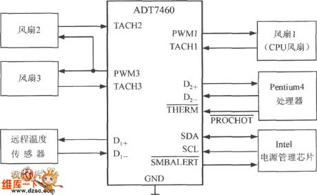
The Pentium 4 computer's thermal dissipation control circuit is shown in the picture. In this computer it all uses three thermal-dissipation fans. Among them, the first fan is special for the CPU's thermal dissipation. The second fan and the third fan are installed separately in the computer's front side and back side for the box's thermal dissipation. The VT is the the first channel's remote temperature sensor which is used for measuring the environment temperature. The temperature sensor in Pentium 4 CPU is used as the second channel remote temperature sensor. The ADT7460 would be connected to the power management chip produced by the Intel company through the SMBus bus. Once it has detected the over-temperature case, it would output the over-temperature interrupt signal from the ports. And then by the power management chip it would make the CPU generate a interrupt. (View)
View full Circuit Diagram | Comments | Reading(564)
On_resistance_current_tests
Published:2009/7/23 21:49:00 Author:Jessie
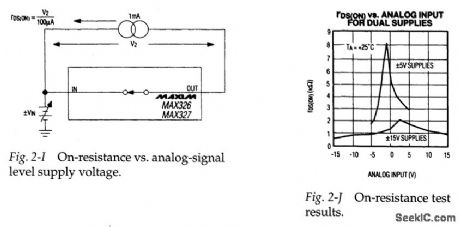
Figure 2-I shows a basic test circuit for measuring on-resistance, r DS(ON) ,for the MAX326/27. Figure 2-J shows how r DS(ON) changes with various analog inputs and supply combinations. Although specified at TTL threshold levels, the logic thresh-old is about 1.5 V± 0.2 V. The IC switches properly with CMOS input levels from -15 V to +15V. Never allow logic levels to exceed supply voltages in any circuit! (View)
View full Circuit Diagram | Comments | Reading(686)
LOW_VOLTS_ALARM
Published:2009/7/5 22:50:00 Author:May
Circuit Notes
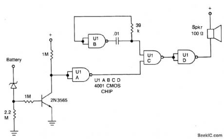
This inexpensive dc supply-voltage monitor sounds a warning when the voltage falls below a preset value. It is ideal for monitoring rechargeable batteries since it draws only a few microamperes when not sounding. The voltage at which the alarm sounds is determined by the zener diode. When the voltage falls below the zener voltage, the alarm sounds. The alarm tone is determined by the RC time constant of the 39 k resistor and 0.01 mf capacitor. (View)
View full Circuit Diagram | Comments | Reading(0)
Basic_rnux_function_tests
Published:2009/7/23 21:56:00 Author:Jessie
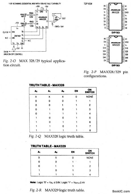
Figures 2-O and 2-P shows the typical application circuit and pin configuration, respectively; for the MAX328/29. Figures 2-Q and 2-R shows the logic truth tables for the MAX328 and MAX329, respectively. This ultra-low-leakage CMOS analog mux is tested by applying and removing +5 V to the control pins, and checking that the corresponding switches open and close. Simple sine waves can be used at the analog inputs, and the op-amp output can be measured on a scope. (View)
View full Circuit Diagram | Comments | Reading(871)
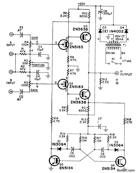
AGC_WITH_SQUELCH_CONTROL
Published:2009/7/5 22:47:00 Author:May

Automatic gain control is a very useful feature in a number of audio amplifier circuits:tape recorders,telephone speaker phones,communication systems and PA systems.This circuit consists of a HA-5144 quad op amp and a FET transistor used as a voltage-controlled resistor to implement an AGC circuit with squelch control.The squelch function helps eliminate noise in communications systems when no signal is present and allows remote hands-free operation of tape recorder systems.Amplifier A1 is placed in inverting-gain T configuration in order to provide a fairly wide gain range and a small signal level across the FET. The small signal level and the addition of resistors R5 and R6 help reduce nonlinearities and distortion.Amplifier A2 acts as a negative peak detector to keep track of signal amplitude.Amplifier A3 can be used to amplify this peak signal if the cutoff voltage of the FET is higher than desired.Amplifier A4 acts as a comparator in the squelch control section of the circuit,When the signal level falls below the voltage set by R10,the gate of the FET is pulled low-turning it off completely-and reducing the gain to 2.4.Theoutput A4 can also be used as a control signal in applications,such as a hands-free tape recorder system.
(View)
View full Circuit Diagram | Comments | Reading(4467)
The constitution circuit diagram of portable rapid pulse generator
Published:2011/6/30 5:39:00 Author:Rebekka | Keyword: portable rapid pulse generator, constitution circuit
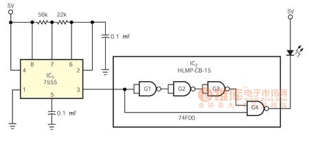
Since the whole TTL series is the lack of a high-speed monostable multivibrator and the ECL requires a small voltage swing and a small range power supply. It drives us to use F series of gates which has fast transition time and small transmission time delay. This requires making a small portable fast pulse generator. It is used to test the high-speed photomultiplier that used in the study of gamma-ray astronomy. The use of only two integrated circuit is to help reduce the consumption and narrow the size(Figure 1). Output the pulse is width from the output gate G4 in IC2. The pulse width is less than 10ns and the rise and fall time of the normal high pulse is about 2.5ns. It is equivalent to the delay of three gates. These pulses are very suitable for decrease the cathode potential of HLMP-CB-15-speed blue LED. But the anode of LED is clamped to 5V. G4 forces almost the entire 5 V supply voltage adding to the LED, so that the large voltage swingof the LED which is printed on circuit board solder connecting to the edge has the best brightness. The rechargeable battery is fixed at the other side of the printed circuit board. The circuit uses CMOS timer IC1, it only costs less than 4 mA of current.
(View)
View full Circuit Diagram | Comments | Reading(2022)
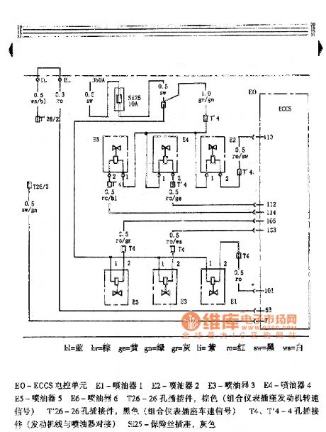
Hongqi Century Star Engine Circuit
Published:2011/8/2 8:22:00 Author:Robert | Keyword: Hongqi, Century Star, Engine
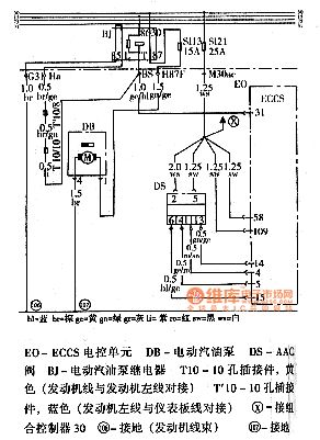
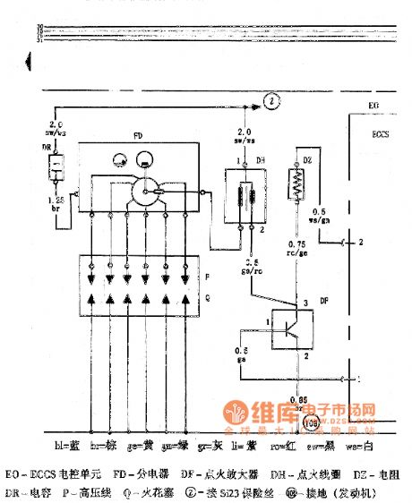
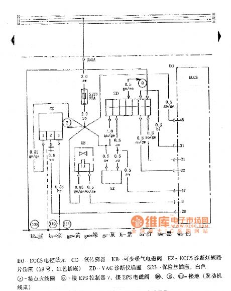
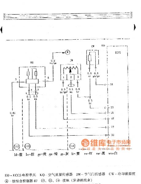
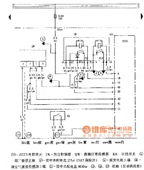
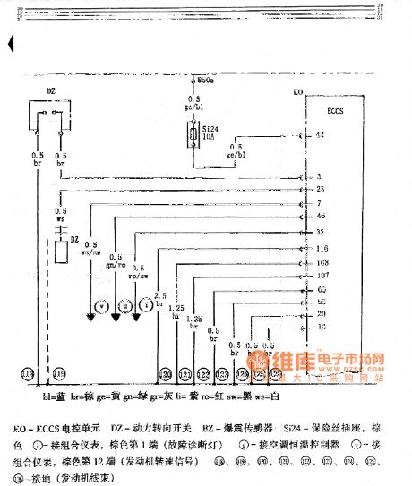
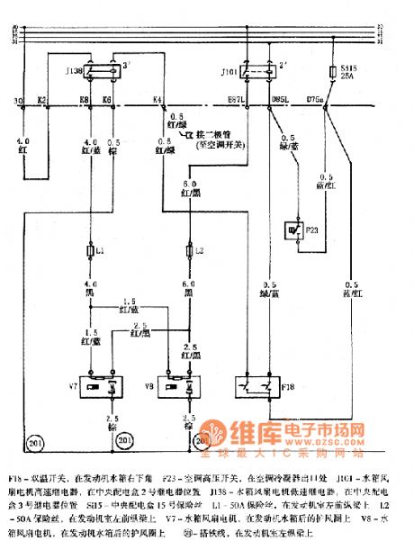
The pictures shown the Hongqi Century Star engine circuits.
In the first picture, the EO is ECCS ECU. The DB is electric fuel pump. The DS is AAC value. The BJ is electric fuel pump relay. The T10 is 10-hole connector and its colour is yellow (engine wire and engine left wire is connected). The T'10 is 10-hole connector and its colour is blue (engine left wire and the dashboard wire is connected).In the second picture the EO is ECCS ECU. The E1 is oil injector 1. The E2 is oil injector 2. The E3 is oil injector 3. The E4 is oil injector 4. The E5 is oil injector 5. The E6 is oil injector 6. The T26 is a 26-hole connector which is brown (instrument cluster socket engine speed signal). The T'26 is a 26-hole connector which is black (instrument cluster socket car speed signal). The T4, T'4 are 4-hole connectors (engine wire and oil injector is connected). The Si25 is fuse socket which is gray. And so on. (View)
View full Circuit Diagram | Comments | Reading(741)
MALFUNCTION_ALARM
Published:2009/7/5 22:42:00 Author:May
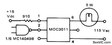
Motorola MOC3011 optoisolator serves as interface between CMOS logic of microprocessor and 5-W 115-VAC lamp.Input logic is connected to energize infrared LED of optoisolator by providing up to 50 mA.Once triggered, indicator lamp remains on until current drops below holding value of about 100 μA.-P. O'Neil, Applications of the MOC3011 Triac Driver, Motorola, Phoenix, AZ, 1978, AN-780,p2. (View)
View full Circuit Diagram | Comments | Reading(1149)
25 ohm speakers overload protection circuit diagram
Published:2011/5/10 1:17:00 Author:Rebekka | Keyword: speakers overload protection
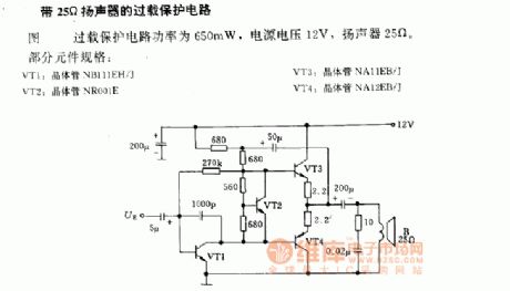
25 ohm speakers overload protection circuit diagramThe power of overload protection is 650mW, power supply voltage is 12V, speaker 25ohm.Part of the component specifications:VT1: Transistor NB111EH/JVT2: Transistor NR001ETV3: Transistor NA11EB/JVT4: Transistor NA12EB/J (View)
View full Circuit Diagram | Comments | Reading(2016)
IONIZATION_ALARM
Published:2009/7/5 22:38:00 Author:May
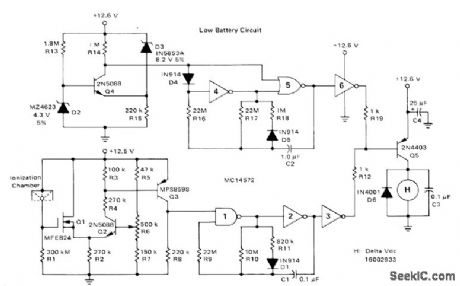
Gates in Motorola MC14572 CMOS IC form two alarm oscillators, one energized in presence of smoke at ionization chamber and other for low battery.Standby currents of circuits are low enough to give at least 1 year of operation from 750-mAh battery. R6 is adjusted to give desired smoke detection sensitivity. Gates 1 and 2 form MVBR that drives horn at astable rate of 2.5 s on and 0.2 s off in presence of smoke. When battery is low, comparator Q4-D2-D3 trips (about 10.5 V) and energizes inverter 4 of low-battery astable MVBR. DC horn is then powered at astable rate of about 1 s every 23 s to give early warning of need to change battery.-A. Pshaenich, Solid State Gas/Smoke Detector Systems, Motorola, Phoenix, AZ, 1975, AN-735, p 7.
(View)
View full Circuit Diagram | Comments | Reading(1124)
Volumn control circuit diagram
Published:2011/6/23 4:23:00 Author:Rebekka | Keyword: Volumn control
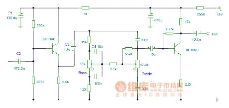
Volumn control circuit diagram. (View)
View full Circuit Diagram | Comments | Reading(598)
4-word control keyboard circuit diagram
Published:2011/5/10 1:34:00 Author:Rebekka | Keyword: 4-word control keyboard
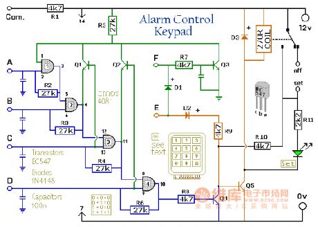
4-word control keyboard circuit diagram. (View)
View full Circuit Diagram | Comments | Reading(853)
| Pages:141/312 At 20141142143144145146147148149150151152153154155156157158159160Under 20 |
Circuit Categories
power supply circuit
Amplifier Circuit
Basic Circuit
LED and Light Circuit
Sensor Circuit
Signal Processing
Electrical Equipment Circuit
Control Circuit
Remote Control Circuit
A/D-D/A Converter Circuit
Audio Circuit
Measuring and Test Circuit
Communication Circuit
Computer-Related Circuit
555 Circuit
Automotive Circuit
Repairing Circuit