
Control Circuit
Index 149
Freezer_alarm
Published:2009/7/24 2:50:00 Author:Jessie
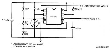
Fig. 13-30 This circuit shows a very simple configuration for a freezer alarm. Such circuits are used in industrial and home freezers as well as in refrigerated trucks and rail cars. The LTC1042 is a sampled-operation window comparator. The 10 MΩ/0.05μF combination sets a sample rate of 1 Hz, and the bridge values program the internal window comparator for the outputs shown. For normal freezer operation, pin 1 is high and pin 6 is low. Over-temperature reverses this state and can trigger an alarm. Circuit current consumption is about 80μA. Linear Technology, Linear Applications Handbook 1990, p. AN23-7.
(View)
View full Circuit Diagram | Comments | Reading(1926)
Battery_powered_wall_thermostat
Published:2009/7/24 2:49:00 Author:Jessie
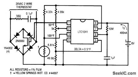
Fig. 13-29 This circuit shows a battery-powered thermostat using an LTC1041.Temperature is sensed using a thermistor connected in a bridge with a potentiometer to set the desired temperature. However, the bridge is not driven from the battery but from pin 7 on the LTC1041. Pin 7 is the pulsed power (Vpp) output and turns on only while the LTC is sampling the inputs, thus keeping average power drain extremely low. A lithium battery will run the circuit for at least 10 years. A 2N6660 power MOSFET in a diode bridge switches the conventional 26 Vac heater-control circuitry. The 2N6660 requires no current from the battery. Linear Technology Linear Applications Handbook 1990 p AN23-6.
(View)
View full Circuit Diagram | Comments | Reading(2320)
UP_TO_1OO_kHz_WITH_322_TIMER
Published:2009/7/2 1:07:00 Author:May
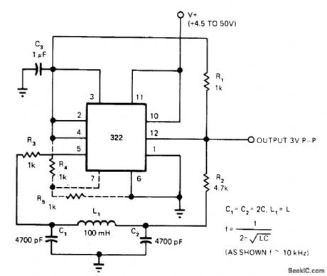
Efficient LC oscillator uses IC timer as inverting comparator, with pinetwork LC tank as resonant circuit. Output square wave is regulated to 3 V in amplitude, independently of supply voltage; upper supply limit should be 40 V instead of value shown. Sine-wave output of oscillator may also be used extemally by adding single-supply opamp as buffer. Values shown give 10 kHz, but upper limit is 100 kHz.-W. G. Jung, Take a Fresh Look at New IC Timer Applications, EDN Magazine, March 20, 1977, p 127-135. (View)
View full Circuit Diagram | Comments | Reading(1835)
RC_CONTROL
Published:2009/7/2 1:04:00 Author:May
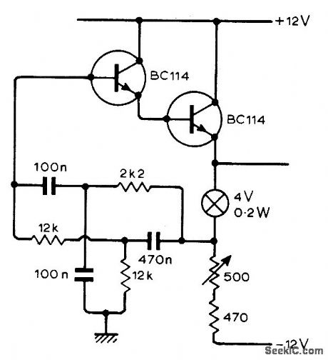
Chief advantage is absence of attenuation at zero phase shift in passive RC network used to define frequency of oscillation. Output is 20 V P-P. Pilot lamp stabilizes loop gain to unity, eliminating need forthermistor.-W. R. Jackson, Oscillator Uses Passive Voltage-Gain Network, Wireless Workl, April 1975, p 175. (View)
View full Circuit Diagram | Comments | Reading(726)
TREMOLO_CONTROL
Published:2009/7/2 0:40:00 Author:May
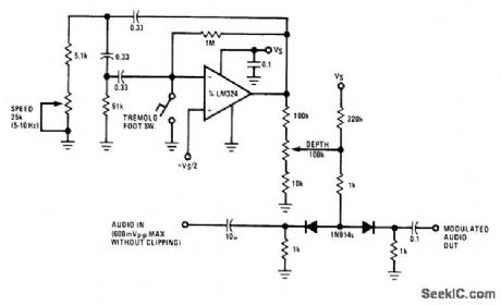
National LM324 opamp connected as phase-shift oscillator operates at variable rate between 5 and 10 Hz set by speed pot. Portion of oscillator output is taken from depth pot and used to modulate ON resistance of two 1N914 diodes operating as voltage-controlled attenuators. Input should be kept below 0.6 V P-P to avoid undesirable clipping. Used for producing special musical effects.- Audio Handbook, National Semiconductor, Santa Clara, GA, 1977, p 5-11-5-12. (View)
View full Circuit Diagram | Comments | Reading(859)
LOGIC_CONTROL
Published:2009/7/2 0:32:00 Author:May
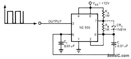
External circuit modification shown for 555 timer makes initial pulse more nearly equal to subsequent pulses and makes circuit deliver low output when power is applied. Optional diode ensures 50% duty cycle.-K. D. Dighe, Rearranged Components Cut 555's Initial-Pulse Errors, EDN Magazine, Jan. 5, 1978, p 82 and 84. (View)
View full Circuit Diagram | Comments | Reading(811)
PULSE_WIDTH_CONTROL
Published:2009/7/2 0:24:00 Author:May
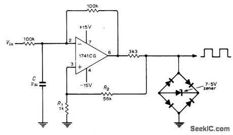
DC input voltage controls width of rectangular output pulse of opamp operating as free-running multivibrator, by injecting additional current into phase-inverting input of opamp. This current serves to increase one timing period and decrease the other. Circuit also provides similarly controllable sawtooth output (at pin 2). Output circuit uses diode bridge and zener for symmetrically clamping output voltage limits of amplifier when this feature is required.-G. B. Clayton, Experiments with Operational Amplifiers, Wire-less World, May 1973, p 241-242. (View)
View full Circuit Diagram | Comments | Reading(763)
DC_VARIABLE_SPEED_MOTOR_CONTROL_VIA_FIBEROPTICS
Published:2009/7/1 23:41:00 Author:May
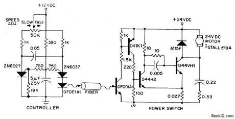
Dc power can also be controlled via fiberoptics. The circuit provides an insulated speed control path for a small dc actuator motor (≤1/12hp). Control logic is a selfcontained module requiring about 300 mW at 12 V, which can be battery powered. The control module furnishes infrared pulses, at a rate of 160 Hz, with a duty cycle deter-mined by the position of the speed adjust potentiometer. The programmable unijunction multivibrator provides approximately 10 mA pulses to the GFOE1A1 at duty cycles adjustable over a range of 1% to 99%. The infrared pulses are detected by the GFOD1A1, amplified by the D39C1 pnp Darlington, and supplied to the power drive switch, which is connected in a Schmitt trigger configuration to supply the motor voltage pulses during the infrared pulses. Thus, the motor's average supply voltage is pulse width modulated to the desired speed, while its current is maintained between pulses by the A115F free-wheeling diode. The snubber network connected in parallel with the power switch minimizes peak power dissipation in the output transistor, and enhancing reliability. Larger hp motors can be driven by adding another stage of current gain, while longer fiber range lengths can be obtained with an amplifier transistor driving the GFOE1A1. (View)
View full Circuit Diagram | Comments | Reading(1024)
Thermocouple_cold_junction_compensation_grounded_thermocouple
Published:2009/7/24 3:06:00 Author:Jessie
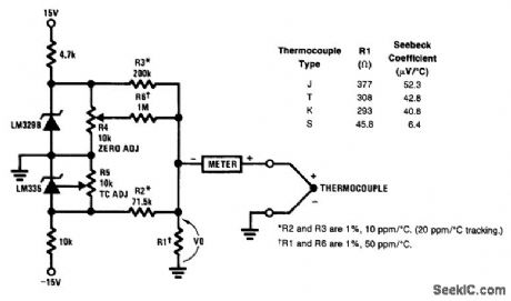
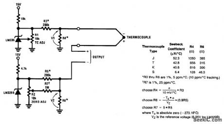
Fig.13-39 This circuit is preferable to that of Fig.13-38, but it requires dualsupplies. To trim, short out the LM329B and adjust R5 so that VO(across R1)equals the Seebeck coefficient(in μV/℃)times the absolute temperature. Remove the short and adjust R4 so that VO, equals the thermocouple output voltage at ambient. This circuit requires good grounding because any ground differential will appear in series with the thermocouple output, National Semiconductor Linear Applications Handbook, 1991, p. 524. (View)
View full Circuit Diagram | Comments | Reading(1474)
High_temperature_thermometer_with_analog_and_digital_outputs
Published:2009/7/24 3:01:00 Author:Jessie
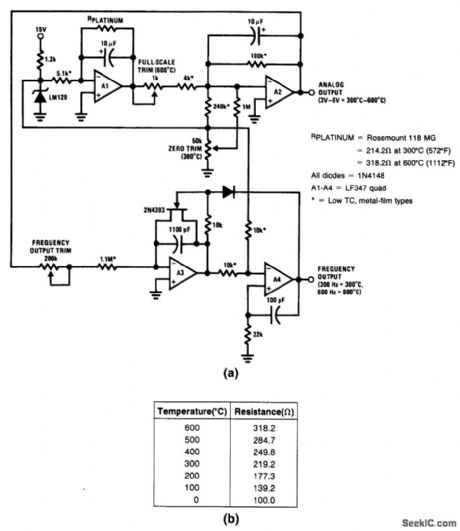
Fig. 13-36 In this circuit, an LF347 is used to signal condition a platinum RTD and provide simultaneous analog and frequency outputs. These outputs are accurate to ±1℃ over a range of300 to 600℃ (572 to 1112°F). Although the circuit maintains linearity over a much wider range, the nonlinear response of the RTD mover wide range is the limiting factor, as shown in the graph of Fig. 13-36B. To calibrate the thermometer, substitute a high-quality decade box (General Radio 1432-KL) for the sensor. Alternately adjust the zero (300℃) and full-scale (600℃) potentiometers for the resistance values noted in Fig. 13-36B until the A2 output is calibrated (3 to 6 V). Then, adjust the 200-kΩ frequency trim so that the output frequency corresponds to the value at the A2 output (300 Hz at the frequency output for 3 V at the analog output). National Semiconductor, Linear Applications Handbook 1991,p. 729.730. (View)
View full Circuit Diagram | Comments | Reading(1651)
HOTEL_ROOM_ALARM
Published:2009/7/1 22:07:00 Author:May
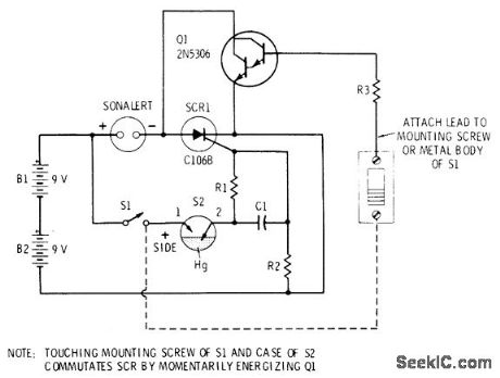
Alarm mounted in flashlight-shaped cylinder is positioned on floor inside hotel room in such a way that it is knocked over by intruder opening door. Mercury switch S2 then triggers SCR and activates Mallory SC-628P pulsed Sonalert alarm. Circuit latches on and can be tumed off only by use of Darlington-amplifier touch switch. Connection from base of Darlington to positive terminal of battery must be made through fingertips as shown by dashed line in orderto silence alarm. Once silenced, S1 can be opened to disconnect latch so alarm can be moved. Other applications include protection of unattended luggage. C1 is 0.1 μF, R1 is 1 megohm, R2 is 1K, R3 is 39K, and S2 is mercury element removed from GE mercury toggle switch,-R. F. Graf and G. J. Whalen, The Build-It Book of Safety Electronics, Howard W. Sams, Indianapolis, IN, 1976, p 19-24. (View)
View full Circuit Diagram | Comments | Reading(1493)
MULTIPLEXED_BRIGHTNESS_CONTROL
Published:2009/7/1 22:03:00 Author:May

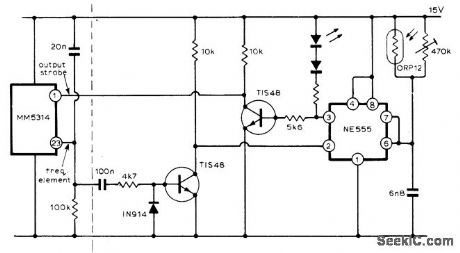
Developed for use with single-chip digital clocks in which several displays are multiplexed. Provides automatic brightness control by using variable duty cycle and switching it on and off in synchronism with display of time. Uses 555 timer in monostable mode, triggered by multiplex oscillator to determine off time of display.When ambient light is bright, resistance of ORP12 photocell is low and display is on most of time. Set 470K pot to give low light output without mistriggering under dark conditions.Timer can also drive decimal point directly and give matched brightness.-M. G. Martin, Automatic Display-Brightness Control, Wireless World, April 1976, p 61. (View)
View full Circuit Diagram | Comments | Reading(817)
Thermocouple_cold_junction_compensation_single_supply
Published:2009/7/24 3:05:00 Author:Jessie
Pig. 13-38 In this single-supply circuit, R3 and R4 divide down the 10-mV/°K output of the LM335 to match the Seebeck coefficient of the thermocouple. The LM329B and associated voltage divider provide a voltage to buck out the 0℃ output of the LM335. To calibrate, adjust R1 so that V1 (across R4) equals the thermocouple Seebeck coefficient (in μV/℃) times the ambient temperature in degrees Kelvin (note that absolute zero in the Kelvin scale -273.18℃). Then, adjust R, so thatV1- V2 (across R6) is equal to the thermocouple output voltage at the known ambient temperature. Note that the term ∞ is used to determine R4 and R6 is the Seebeck coefficient for the type of thermocouple selected (types J, T, K, or S). National Semtconductor Linear Applications Handbook 1991 p 523. (View)
View full Circuit Diagram | Comments | Reading(2056)
SPEED_ALARM
Published:2009/7/1 21:39:00 Author:May
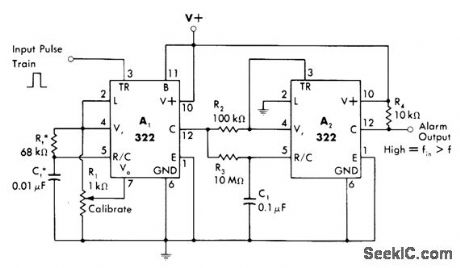
Frequency detector using two IC timers provides alarm output when input frequency is greater than reference frequency, corresponding to overspeed. Calibrated mono MVBR A1 produces fixed-width positive pulse across R2, with average voltage of pulse varying linearly with input pulse train frequency. ComparatorA2 changes states when integrated output of R3-C1 on pin 5 goes above or below 2-V voltage threshold of A2. With values shown, desired frequency is 1 kHz and circuR detects frequency variation of less than 1%. If low-frequency alarm is desired, connect logic input pin 2 of A2 to reference voltage (pin 4) instead of to ground.-W. G. Jung, IC Timer Cookbook, Howard W. Sams, Indianapolis, IN, 1977, p 228-230. (View)
View full Circuit Diagram | Comments | Reading(0)
PWM_BRIGHTNESS_CONTROL
Published:2009/7/1 21:37:00 Author:May
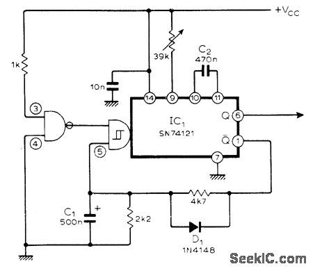
Single TTL IC combines functions of oscillator and modulator to provide intensity control of solid-state display by pulse-width modulation. Fan-out of 10 is available from Q output, suitable for displays such as Hewlett-Packard 7300 series, and smaller fan-out is available from other Q terminal.-C. Bartram, P.W.M. Oscillator to Vary Display-Intensity, Wireless World, March 1976, p 89. (View)
View full Circuit Diagram | Comments | Reading(1423)
Proportional_temperature_controller_1
Published:2009/7/24 3:03:00 Author:Jessie
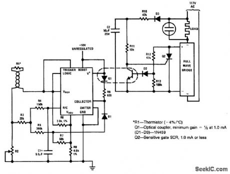
Fig. 13-37 This circuit provides proportional temperature control with optical isolation and synchronized zero crossing. Proportional control is provided by an LM122 timer, although the timing function is not used. Instead, the trigger terminal is held high and the LM122 is used as a high-gain comparator with a built-in reference. R2 sets the temperature to be controlled by R1. R5 and R7 set the width of proportioning band and can be scaled as necessary to alter the band width (larger resistors made the band narrower). The values shown give about a 1℃ band. R4 and C1 set the proportioning frequency, which is about 1 Hz with the values shown. R12, R13, and D2 produce the synchronized zero-crossing feature by preventing Q1 from turning off after the voltage across Q2 has climbed above 2.5 V. Any unregulated supply between 6 and 15 V is satisfactory. National Semiconductor Linear Applications Handbook 1991 p 337. (View)
View full Circuit Diagram | Comments | Reading(1597)
0_to_500℃_furnace_exhaust_gas_temperature_monitor
Published:2009/7/24 3:14:00 Author:Jessie
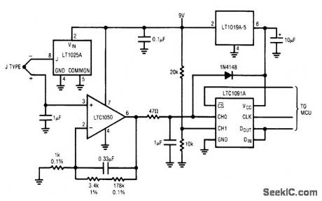
Fig. 13-44 This circuit measures exhaust-gas temperature in a furnace. The 10-bit LTC1050 gives 0.5℃ resolution over a 0 to 500℃ range. The type-J thermocouple characteristic is linearized digitally inside the MCU. Linear interpolation between known temperature points spaced 30℃ apart introduces less than 0.1℃ error. The code for linearizing is available from Linear Technology. Linear Technology, Linear Applications Handbook 1990, p DN5-1. (View)
View full Circuit Diagram | Comments | Reading(633)
ENLARGER_TIMER
Published:2009/7/1 21:24:00 Author:May
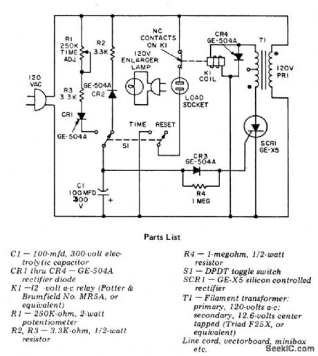


Circuit NotesThis precision, solid state, time delay circuit has delayed off and delayed on switch-ing functions that are interchangeably available by simply interchanging the relay contacts. (View)
View full Circuit Diagram | Comments | Reading(0)
Linearized_platinum_RTD_thermometer_single_supply
Published:2009/7/24 3:13:00 Author:Jessie
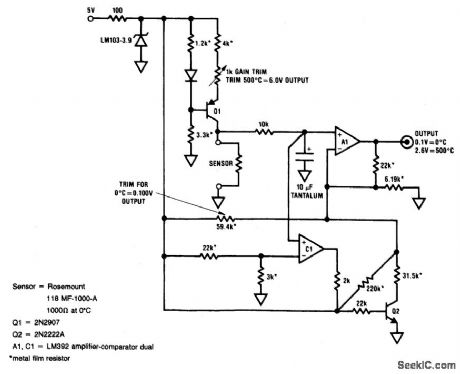
Fig. 13-43 In this circuit, an LM392 comparator/op amp (A1 and C1) is used to provide both gain and linearization for a platinum RTD in a single-supply thermometer, which measures from 0 to 500℃ with ±1℃ accuracy. To calibrate, substitute a precision resistance box for the sensor, adjust 0℃ for 0.10-V output (with the box set to 1000 ohms). Next, set the box to 2846Ω (500℃) and adjust the 1-kΩ gain trim for an output of 2.6 V. Repeat the adjustments until both zero and full-scale are fixed. National Semiconductor Linear Applications Handbook 1991 p 838. (View)
View full Circuit Diagram | Comments | Reading(931)
Electronic_thermometer
Published:2009/7/24 3:11:00 Author:Jessie
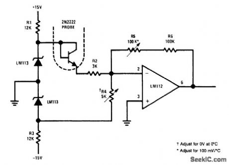
Fig. 13-42 This very simple circuit is an electronic thermometer using an inexpensive silicon transistor (2N2222) as the temperature sensor or probe. The circuit provides better than 1℃ accuracy over a 100℃ range. An LM113 diode regulates the input voltage to 1.2 V. The 1.2 \/ is applied through R2 to set the operating current of the temperature-sensing 2N2222. R4 biases the amplifier output for zero output at 0℃, while feedback resistor R5 calibrates the output scale factor to 100 mV/℃. Once the output is zeroed, the scale factor does not change the zero. National Semiconductor Linear Applications Handbook 1991, p 171. (View)
View full Circuit Diagram | Comments | Reading(0)
| Pages:149/312 At 20141142143144145146147148149150151152153154155156157158159160Under 20 |
Circuit Categories
power supply circuit
Amplifier Circuit
Basic Circuit
LED and Light Circuit
Sensor Circuit
Signal Processing
Electrical Equipment Circuit
Control Circuit
Remote Control Circuit
A/D-D/A Converter Circuit
Audio Circuit
Measuring and Test Circuit
Communication Circuit
Computer-Related Circuit
555 Circuit
Automotive Circuit
Repairing Circuit