
Control Circuit
Index 143
Homemade multi-purpose remote control circuit
Published:2011/7/25 22:20:00 Author:Christina | Keyword: Homemade, multi-purpose, remote control circuit
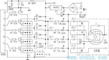

This remote controller uses the miniaturization wireless remote control 4-bit special component which is produced by the XinLi electronic instrument Co., LTD, it is composed of a 4-bit buckle type transmitter, the power supply uses the A23 type 12V battery with small size. The recevier circuit is the KL668 type, the power supply is 9V DC, the voltage of the control relay is decided by the relay, the relay in this figure is 12V. This receiving circuit has strong anti-interference ability, the control distance is 20-40 miles.
(View)
View full Circuit Diagram | Comments | Reading(939)
Crosstalk_tests
Published:2009/7/23 22:06:00 Author:Jessie
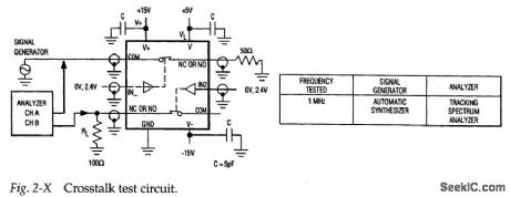
Figure 2-X shows a test circuit for measuring the isolation between channels (or the lack of crosstalk when the channel switches are closed) for the MAX301/3/5.Typical crosstalk isolation is 90 dB. (View)
View full Circuit Diagram | Comments | Reading(730)
FAIL_SAFE_ALARM
Published:2009/7/5 21:28:00 Author:May
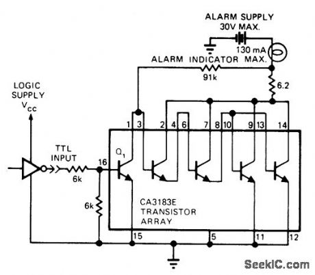
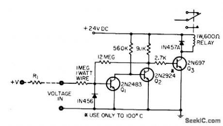
Circuit monitors status of microprocessor system and energizes lamp or other alarm indicator to indicate when CPU halts or power is lost. Input is TTL-compatible, and output can drive loads up to 130 mA at 30 V.-J. Elias, Alarm Driver Is Fail-Safe, EDN Magazine, May 20, 1975, p 76. (View)
View full Circuit Diagram | Comments | Reading(838)
Off_isolation_tests
Published:2009/7/23 22:05:00 Author:Jessie
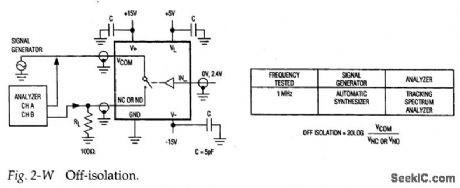
Figure 2-W shows a test circuit for measuring the isolation between channels (when the channel switch is open) for the MAX301/3/5. Typical isolation is 72 dB, (View)
View full Circuit Diagram | Comments | Reading(714)
LEAKAGE_TESTER_1
Published:2009/7/23 22:05:00 Author:Jessie
High-reliability current-detecting Schmitt trigger responds to nanoampere inputs for leakage testing of capacitors, diodes, and insulation, yet is not damaged or even affected by overloads of 1,000 v at input. Input of 300 no will trigger output relay.-P. Lefferts, Schmitt Triggers on Nanoamp Inputs, EEE, 14:6, p 91. (View)
View full Circuit Diagram | Comments | Reading(1117)
Fault_tolerant_mux
Published:2009/7/23 22:14:00 Author:Jessie
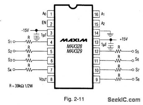
Figure 2-11 shows how the MAX328/29 (Figs, 2-O, 2-P) can be converted to a fault-tolerant mux. The internal diodes limit the voltage at the input to±15.7 V (±15-V supplies). No external diodes are required. The resistors limit power dissipation to 0.28 W when a 120-Vac fault occurs. MAXIM HIGH-RELIABILITY DATA BOOK, 1993, P. 1-6. (View)
View full Circuit Diagram | Comments | Reading(748)
HT-7605 (alarm, lighting and industrial control) pyroelectric infrared receiver control circuit
Published:2011/8/1 4:21:00 Author:Christina | Keyword: alarm, lighting, industrial control, pyroelectric, infrared, receiver control
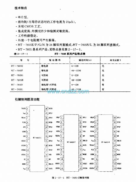
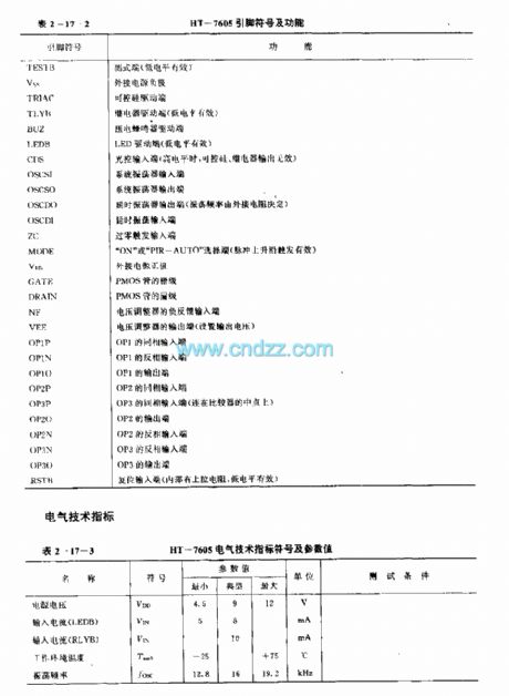
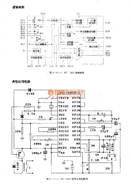
The HT-7605 is designed as the pyroelectric infrared receiver control circuit that can be used in the alarm, lighting and industrial control applications. The internal circuit is composed of the system oscillator, the delay oscillator, the voltage regulator, the operational amplifier, the voltage stabilizer, the latch circuit, the delay circuit, the zero crossing trigger circuit, the control circuit, the beep excitation circuit, the LED excitation circuit, the relay excitation circuit, the SCR excitation circuit and the testing circuit.
Features
Single chip type.Micro-power consumption.High integration, little external components, high sensitivity.Stable performance.
(View)
View full Circuit Diagram | Comments | Reading(528)
DC_MOTOR_CONTROL
Published:2009/7/5 21:21:00 Author:May
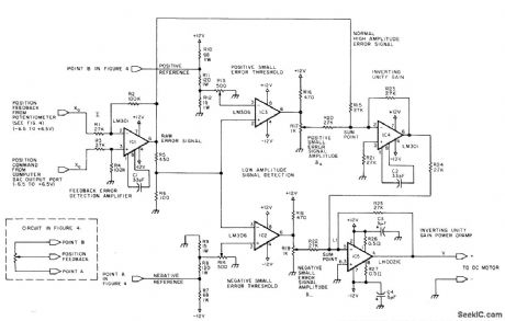
Developed for use in realistic Iunar lander simulation display. Throttle signal and altitude signal serve as inputs to microprocessor. Feedback position-measuring pot is geared to 12-VDC motor so fuil travel of pot shaft occurs while lunar module traverses full altitude range. Circuit provides minimum drive voltage required by DC motor for motion to occur. Output of difference amplifier IC1 goes to summing amplifier IC4 as one component of final motor voltage. Comparators IC2 and IC3 sense when difference voltage is larger than small positive voltage set by R13 or smallerthan small negative voltage set by R14. Comparator output then becomes 12 V, and portion of this (about 2 V) drives motor into operating range.IC5 is high-power opamp delivering 1 A at 12 V.-L. Sweer,T. Dwyer, and M. Critchfield, Controlling Small DC Motors with Analog Signals, BYTE, Aug. 1977, p 18-20, 22, and 24. (View)
View full Circuit Diagram | Comments | Reading(2406)
Bistable switch control circuit composed of the T996/998C
Published:2011/8/1 2:04:00 Author:Christina | Keyword: Bistable, switch control circuit
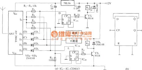
The T996 component is designed as the SAW type wireless remote control launch component with the digital coding circuit, the internal circuit structure of it is the same as the CS900, but it uses the PT2262 digital coding circuit. Also it is designed as the four-channel remote control transmitter, the transmitting frequency is 418MHz. The T998 component is designed as the radio receiver device that can be used with the T996, the internal circuit is the same as the CS902, but the T998 has the digital decoding circuit PT2272.
The bistable switch control circuit which is composed of the T998C-6V and the dual D flip-flop trigger is as shown in figure (a). The four output ports D1~D4 of the T998C-6V control the turn of the four bistable flip-flops respectively to achieve the on-off of the channels.
(View)
View full Circuit Diagram | Comments | Reading(753)
15_MINUTE_SCS_TlMER
Published:2009/7/23 22:21:00 Author:Jessie
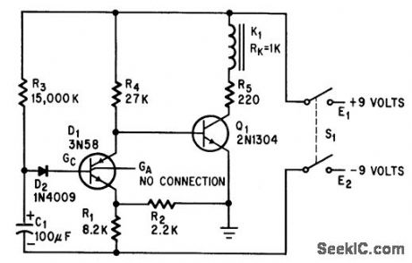
Transistor and silicon controlled switch together serve to open relay 15 minutes after it is activated by man ual dosing of battery switch, for operating recording instruments.-T. H. Charters, Low-Cost Time Delay Controls Recorder, Electronics, 37:18, p 84. (View)
View full Circuit Diagram | Comments | Reading(650)
Negative_variable_voltage_reference_VSUBOUT_SUB_is_higher_than_reference_zener
Published:2009/7/23 22:21:00 Author:Jessie
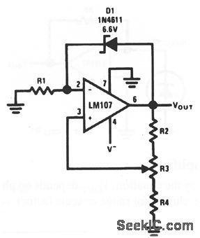
This circuit is similar to that of Fig. 10-45, except that a variable negative-voltage reference is provided at VOUT (View)
View full Circuit Diagram | Comments | Reading(817)
16_channel_sequential_differential_mux_demux
Published:2009/7/23 22:19:00 Author:Jessie
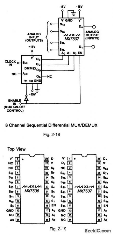
Figures 2-18 and 2-19 show a typical application circuit and pin configurations, respectively, for the MAX7506/07. This circuit is similar to that shown in Fig. 2-17, but with 16-channel operation. MAXIM HIGH-RELIABILITY DATA Book, 1993, P. 1-49. (View)
View full Circuit Diagram | Comments | Reading(778)
8_channel_sequential_differential_mux_demux
Published:2009/7/23 22:18:00 Author:Jessie

Figures 2-16 and 2-17 show a typical application circuit and pin configurations, respectively, for the MAX7501/02/03. In this circuit, the IC acts as a multiplexer or demultiplexer by inter-changing the analog inputs and outputs. Each channel is sampled in sequence by signals from a DM7493 under the control of an external clock. MAXIM HIGH-RELIABILITY DATA Book, 1993, P.1-47. (View)
View full Circuit Diagram | Comments | Reading(1732)
Minimizing_phase_distortion_
Published:2009/7/23 22:17:00 Author:Jessie
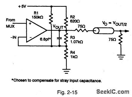
Figure 2-15 shows a circuit used to minimize phase distortion at a mux output. MAXIM HIGH-RELIABILITY DATA Book, 1993, P. 1-46. (View)
View full Circuit Diagram | Comments | Reading(579)
ZERO_CROSSING_SYNCHRONIZER
Published:2009/7/23 22:16:00 Author:Jessie
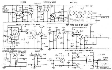
Variable-frequency sinusoidal wavetrain output, starting at zero crossing, is produced by gating circuit. Used to determine attenualion and velocity characteristics of ultrasonic delay lines. Covers 20 cps to 300 kc. External blocking oscillator allows use of alternative repetition rate generator when required.-J. A. Wereb, J., Zero-Crossing Technique Syncs Wavetrain Outputs, Electronics, 32:19, p 64-65.
(View)
View full Circuit Diagram | Comments | Reading(0)
Isolating_capacitive_loads
Published:2009/7/23 22:16:00 Author:Jessie
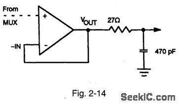
Figure 2-14 shows a circuit used to isolate a mux output that feeds into a large capacitive load. MAXIM HIGH-RELIABILITY DATA Book, 1993, P. 1-46. (View)
View full Circuit Diagram | Comments | Reading(567)
MAGNETOSTRICTION_TV_REMOTE_CONTROL
Published:2009/7/23 22:20:00 Author:Jessie
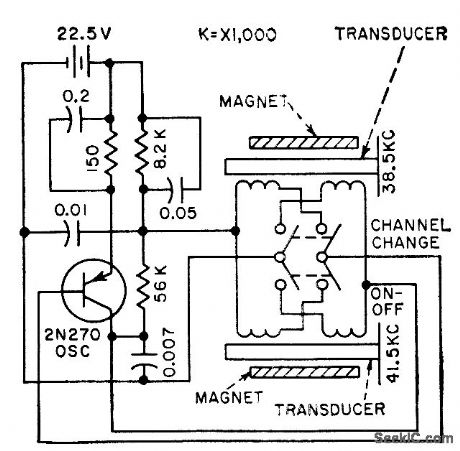
Frequency of transistor oscillator is controlled by either of two lengths of nickel tubing, each looting inside form having two coil windings. One coil acts as driver and the other as pickup to provide feedback voltage for sustaining oscillation at control frequencies of 38.5 and 41.5 kc. Aluminum diaphragms on front ends of tubing increase acoustic output.-N. Frihart and J. Krakora, Ultrasonic Tones Select Tv Channels, Electronics, 31 :23, p 68-69. (View)
View full Circuit Diagram | Comments | Reading(787)
Sample_hold_circuit
Published:2009/7/23 22:20:00 Author:Jessie
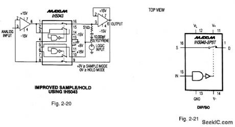
Figures 2-20 and 2-21 show a typical application circuit and pin configuration/ switching-state, respectively, for the IH5040-IH5045/47. These general-purpose CMOS analog switches are latch-up proof, with 1-nA leakage current and less than 1-μA quiescent current. MAXIM HIGH-RELIABILITY DATA BOOK, 1993, P. 1-153. (View)
View full Circuit Diagram | Comments | Reading(1687)
REMOTE_TV_VOLUME_CONTROL
Published:2009/7/23 22:19:00 Author:Jessie
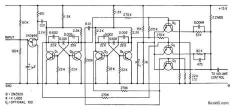
Ultrasonic bursts from handheld transmitter are picked up by microphone and fed to ujt threshold detector 2N2646 that also generates trigger pulse. Two cascaded bistable dividers control three transistors shunted across volume control, to give full volume (no shunting) and three lower volume levels.-J. H. Phelps, Transistors Instead of Relays Tune TV Volume, Electronics, 37:9, p 32-33. (View)
View full Circuit Diagram | Comments | Reading(813)
4_2_differential_mux_MAX335
Published:2009/7/23 22:24:00 Author:Jessie
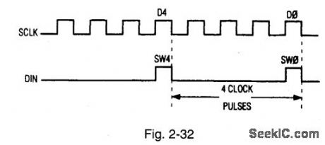
To use the MAX335 as a 4-X-2 differential mux, tie COMO through COM3 together and COM4 through COM7 together, Differential inputs will be at the source inputs as follows: (N00, N04), (N01, N05), (N02, N06), and (N03, N07). Figure 2-32 shows the serial input control at DIN required to turn on two switches to form a differential mux. CS is held low for four clock pulses; the first pulse is clocked into the fifth swith position as the second pulse is clocked into the first switch position. CS is pulled high to update the switches; ten CS is pulled low, and SCLK advances pulses to S1 and S5 positions, where CS is pulled high to update, etc. (View)
View full Circuit Diagram | Comments | Reading(700)
| Pages:143/312 At 20141142143144145146147148149150151152153154155156157158159160Under 20 |
Circuit Categories
power supply circuit
Amplifier Circuit
Basic Circuit
LED and Light Circuit
Sensor Circuit
Signal Processing
Electrical Equipment Circuit
Control Circuit
Remote Control Circuit
A/D-D/A Converter Circuit
Audio Circuit
Measuring and Test Circuit
Communication Circuit
Computer-Related Circuit
555 Circuit
Automotive Circuit
Repairing Circuit