
Control Circuit
Index 153
SCR_REED_A_C_SWITCH
Published:2009/7/24 4:18:00 Author:Jessie
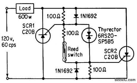
Magnetic reed switch makes ideal trigger for silicon controlled rectifiers, even though nine components are required for switching 600.w load.-M. P. Southworth, Bidirectional Static Switch Simplifies Ac Control, Control Engineering, March 1964, p 75-76. (View)
View full Circuit Diagram | Comments | Reading(794)
TRANSISTOR_SWITCHED_IGNITION
Published:2009/7/24 4:18:00 Author:Jessie
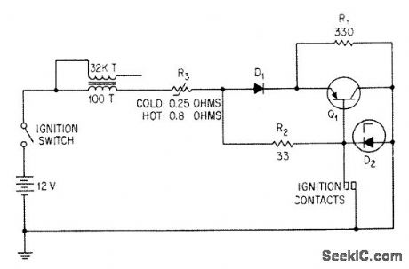
Ignition breaker points handle only current of about 0.25 amp for switching transistor Q1, in-creasing contact life, while transistor handles 9-amp peak ignition coil current. Diode D1 reverse-biases emitter-base junction when distributor contacts are open, to ensure transistor cutoff at high temperaturs. Zener D2 dips peaks of transients that might damage transistor.-S. B. Gray, Home and Auto Controls, Electronics, 36:19, p 52-56. (View)
View full Circuit Diagram | Comments | Reading(2520)
UNGROUNDED_SWITCH_SCS_CONTACT_ISOLATOR
Published:2009/7/24 4:26:00 Author:Jessie
Eliminates contact bounce when switch is dosed to trigger scs, because load current increases rapidly and latches on.- Transistor Manual, Seventh Edition, General Electric Co., 1964, p 433. (View)
View full Circuit Diagram | Comments | Reading(702)
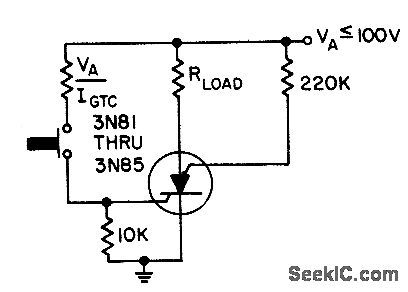
GROUNDED_SWITCH_SCS_CONTACT_ISOLATOR
Published:2009/7/24 4:25:00 Author:Jessie
Eliminates contact bounce when switch is closed to trigger scs, because load current increases rapidly and latches on.- Transistor Manual, Seventh Edition, General Electric Co., 1964, p 433. (View)
View full Circuit Diagram | Comments | Reading(696)
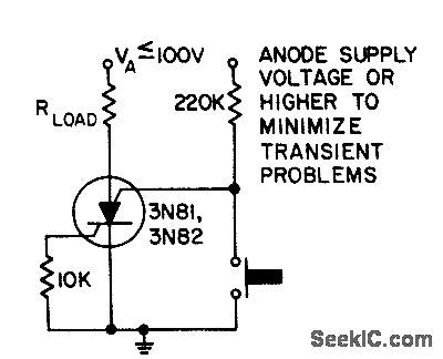
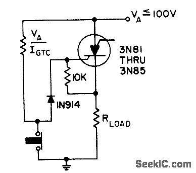
SCS_CONTACI_ISOLATOR_2
Published:2009/7/24 4:25:00 Author:Jessie
Eliminates contact t bounce when switch is closed to trigger scs, with both switch and load grounded.- Transistor Manual, Seventh Edition, General Electric Co., 1964, p 433. (View)
View full Circuit Diagram | Comments | Reading(603)
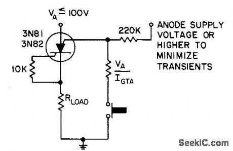
SCS_CONTACT_ISOLATOR_1
Published:2009/7/24 4:24:00 Author:Jessie
Eliminates contact bounce when both switch and load are grounded and opening of switch triggers scs. - Transistor Manual, Seventh Edition, General Electric Co., 1964, p 433. (View)
View full Circuit Diagram | Comments | Reading(662)
FAST_SWITCHING_OF_A_C_POWER
Published:2009/7/24 4:23:00 Author:Jessie
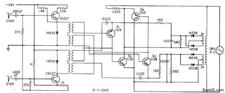
Pulsed scr's Q1 and Q2 turn on load-current-carrying scr's Q3 and Q4 under control of start-stop pulses from an external vibrator that feeds the 2N527 start-stop pulse amplifiers. Each pulsed scr has its own 3-V source. Load being switched requires 350 ma at 400 cps.-J. E. Roberts, Controlled Rectifiers for Fast Power Switching, Electronics, 35:17, p 58-59. (View)
View full Circuit Diagram | Comments | Reading(748)
MEMORY_MATRIX_SWITCHING
Published:2009/7/24 4:28:00 Author:Jessie
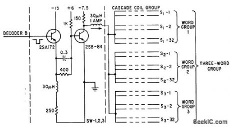
Output terminal, connected to throe word coil groups of matrix, is grounded when pulse appears at input.-J. Yamato and Y. Suzuki, Forming Semi-Permanent Memories with Metal Cord Storage, Electronics, 34:46, p 136-141. (View)
View full Circuit Diagram | Comments | Reading(684)
A_C_RELAY_DRIVE
Published:2009/7/24 4:28:00 Author:Jessie
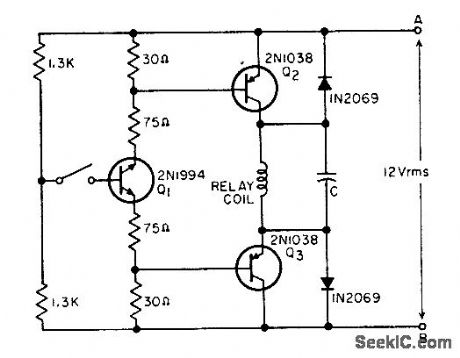
Drives 12-V ac relay with transistors triggered by low direct current of pair of switch contacts. Can drive any a-c relay rated in voltage up to breakdown rating of transistors.-R. K. Walters, Transistor Driven AC Relay, EEE, 11:2, p 25-26. (View)
View full Circuit Diagram | Comments | Reading(1273)
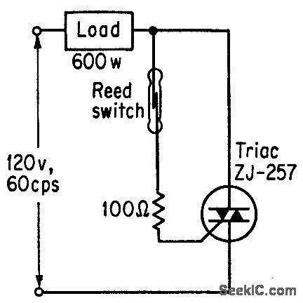
TRIAC_REED_A_C_SWITCH
Published:2009/7/24 4:27:00 Author:Jessie


Gale-controlled semiconductor switch (GE Triac) and magnetic reed switch provide on-off ac switching with minimum components. Gate signal of 3 V at 50 ma, either polarity, triggers Triac for handling 600.W load.-M. P. South. worth, Bidirectional Static Switch Simplifies Ac Control, Control Engineering, March 1964, p 75-16. (View)
View full Circuit Diagram | Comments | Reading(2347)
Chopper_stabilized_comparator
Published:2009/7/24 4:58:00 Author:Jessie
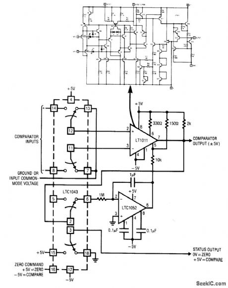
Fig. 15-39 This circuit uses an LTC1043 (Fig. 1-4B) to stabilize a high-speed low-drift comparator. The circuit is applicable only in situations where some dead time is available for zeroing action to occur. Comparator offset is well within 5μV, with negligible temperature drift. Notice that the status output (pin 3) should be used to indicate the circuit operating state, rather than the zero command (pin 16), because the status-output timing includes the 50-ns delay of the LTC1043 switch. Linear Technology Linear Applications Handbook 1990, p. AN9-11. (View)
View full Circuit Diagram | Comments | Reading(1107)
Light_controlled_one_shot_timer
Published:2009/7/24 4:57:00 Author:Jessie
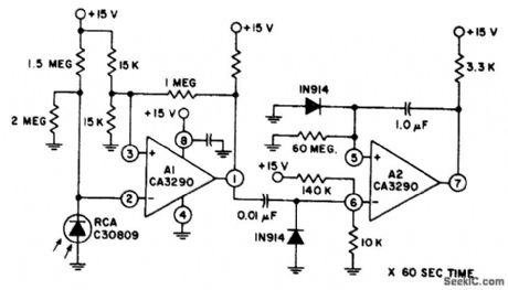
Fig. 15-38 In this circuit, comparator A1 is used to sense a change in photodiode current, and A2 operates as a one-shot timer and is triggered by A1. The A2 output switches low for about 60 seconds after the light source is interrupted. The circuit operates at normal room-lighting levels. Circuit sensitivity can be adjusted by changing the values of the l-MΩ/2-MΩ resistors, but the ratio of these resistors should be constant. Figures 15-30B and 15-30C show the pin connections and electrical characteristics, respectively. Harris Semiconductor Linear & Telecom ICs. 1991. p. 4-22. (View)
View full Circuit Diagram | Comments | Reading(706)
DIGITAL_ALARM
Published:2009/7/1 2:16:00 Author:May
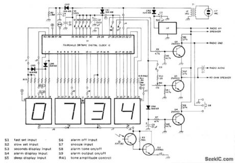
Direct drive offered by Fairchild 3817 IC allows design of simple Iow-cost clock radio providing display drive, alarm, and sleep-to-music features in 12- or 24-h formats.Display is Fairchild FND500 LED. Either 50- or 60-Hz input may be used. U2 is 7800-series IC volt-age regulator rated to meet requirements of radio used. Q3 provides active low output for timed radio turnoff after user-selected interval of up to 59 min. CR4 and C5 rectify alarm-tone output for amplification by Q4 to give active low output for timed radio turn-on when coincidence is detected by alarm comparators. Q5 provides alarm-tone output at level sufficient to drive 40-ohm loudspeaker with ample wake-up volume. If radio is used, omit loudspeaker. Article covers construction and adjustment.-D.Ft. Schmieskors, Jr., Low-Cost Digital Clock, Ham Radio, Feb. 1976,p 26-30.
(View)
View full Circuit Diagram | Comments | Reading(6497)
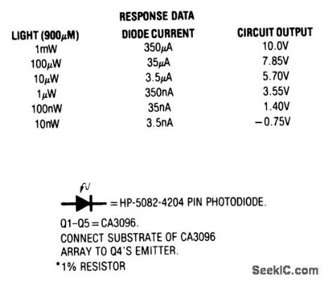
THERMALLY_STABILIZED_PPIN_PHOTODIODE_SIGNAL_CONDITIONER
Published:2009/7/1 1:50:00 Author:May
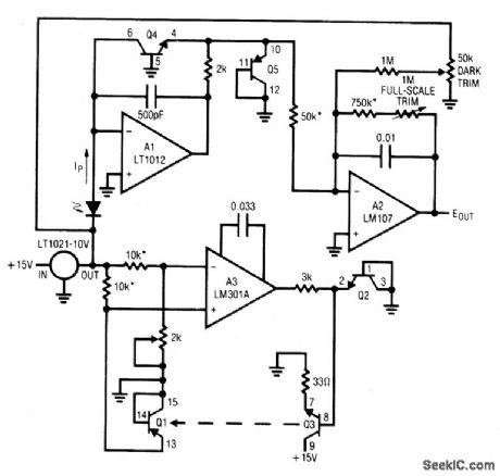
The photodiode specified responds linearly to light intensity over a 100 dB range.Digitizing the diodes linearly amplified output would require an A-D converter with 17 bits of range. This requirement can be eliminated by logarithmically compressing the diode's output in the signal conditioning circuity. Al and Q4 convert the diode's photocurrent to voltage output with a logarithmic transfer function. A2 provides offsetting and additional gain. A3 and its associated components form a temperature control loop
which maintains Q4 at constant temperature (all transistors in this circuit are part of a CA3096 monolithic array). The 0.033μF value at A3's compensation pins gives good loop damping if the circuit is built using the array's transistors in the location shown.
Because of the array de's small size, response is quick and clean. A full-scale step requires only 250 ms to settle to final value. To use this circuit, first set the thermal control loop.To do this, ground Q3's base and set the 2 k pot so A3's negative input voltage is 55 mV above its positive input. This places the servo's setpoint at about 50℃(25℃ ambient + (2.2 mV/℃, x 25℃ rise = 55 mV = 50℃). Unground Q3's base and the array will come to temperature. Next, place the photodiode in a completely dark environment and adjust the dark trim so A2's output is 0 V. Finally, apply or electrically simulate 1 mW of light and set the full-scale trim for 10 V out. Once adjusted, this circuit responds logarithmically to light inputs from 10nW to 1mW with an accuracy limited by the diode's 1% error.
(View)
View full Circuit Diagram | Comments | Reading(804)
MONOSTABLE_PHOTOCELL_CIRCUIT_HAS_SELF_ADJUSTING_TRIGGER_LEVEL
Published:2009/7/1 1:49:00 Author:May
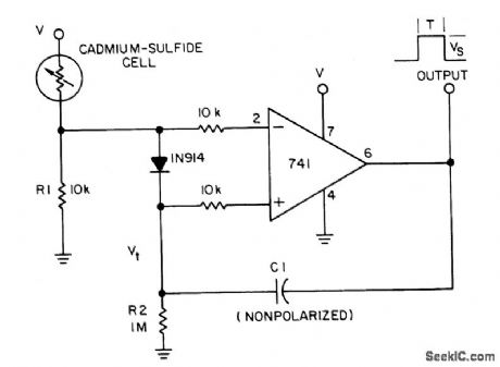
A photocell circuit provides automatic threshold adjustment. Monostable actionprevents undesired retriggering of the output. With only one op amp IC,the circuit offers:Automatic adjustment of its trigger level to accommodate vanous light Sources,changesh ambient light and misalignments;A built-in monostable action to provide only a singleoutput pulse during a preset time;Feedback action toralse the threshold level aftertriggering and to speed switching.The feedback also eliminates the circuit's tendencyto oscillate during switching (View)
View full Circuit Diagram | Comments | Reading(2189)
SYNCHRONOUS_PHOTOELECTRIC_SWITCH
Published:2009/7/1 1:43:00 Author:May
Synchronous switching is turning on only at the instant the ac supply voltage passes through zero, and turning off only when ctyrent passes through zero. This circuit provides this function in response to either a mechanical switch or a variable resistance such as a cadmium-sulfide photocell. This circuit produces the minimum disturbance to the power supply when switching, and always conducts an integral number of whole cycles. It is ideal for use wherever RFI and audio filtering is undesirable, where magnetizing inrush current of transformers causes nuisance fuse-blowing, and where sensitive equipment must operate in the vicinity of power switches. (View)
View full Circuit Diagram | Comments | Reading(1174)
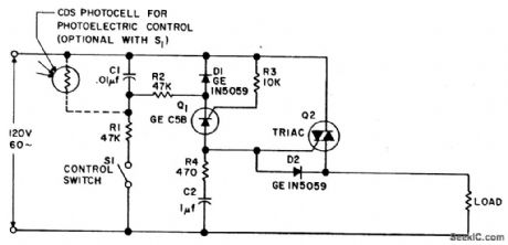
TRIAC_ZERO_POINT_SWITCH
Published:2009/7/1 1:21:00 Author:May
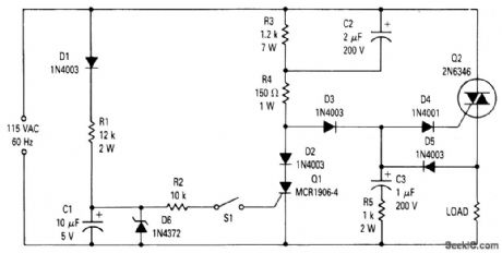
On the initial part of the positive half cycle, the voltage is changing rapidly from zero causing a large current to flow into capacitor C2. The current through C2 flows through R4, D3, and D4 into the gate of the TRIAC Q2 causing it to turn on very close to zero voltage. Once Q2 turns on, capacitor C3 charges to the peak of the line voltage through D5. When the liqe voltage passes through the peak, D5 becomes reverse-biased and C3 begins to discharge through D4 and the gate of Q2. At this time the voltage on C3 lags the line voltage. When the line voltage goes through zero there is still some charge on C3 so that when the line voltage starts negative C3 is still discharging into the gate of Q2. Thus Q2 is also turned on near zero on the negative half cycle. This operation continues for each cycle until switch 51 is closed, at which time SCR Q1 is turned on.Q1 shunts the gate current away from Q2 during each positive half cycle keeping Q2 from turning on. Q2 cannot turn on during the negative cycle because C3 cannot charge unless Q2 is on during the positive half cycle. (View)
View full Circuit Diagram | Comments | Reading(1209)
AUTOMATIC_LIGHT_CONTROLLER_FOR_CARPORT
Published:2009/7/1 1:15:00 Author:May
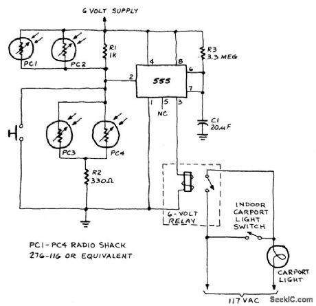
A 555 timer IC, operating in the one-shot mode, is triggered by light striking photoresistors. These normally have a resistance of several megohms but, in the pres-ence of light, that resistance drops to several hundred ohms, permitting current from the six-volt source to flow in the circuit. The R-C combination shown gives an on-time of about two minutes. Photoresistors PC3 and PC4 are mounted at heatlight-height. When headlights illuminate the photoresistor, the timer starts. That actuates a relay, RY1, and the lights are turned on. The lights are automatically turned off when the timer's two minutes are up. (View)
View full Circuit Diagram | Comments | Reading(1077)
DC_LAMP_DIMMER
Published:2009/7/1 1:15:00 Author:May
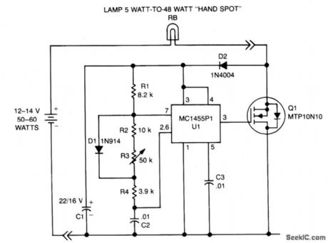
A low power, low cost dc lamp dimmer for a two-wire portable flashlight can be realized with little or no heatsinking. In addition, a single potentiometer, R3 adjusts lamp brightness.Battery power is stored in C1 for U1, which is a free-running multivibrator whose frequency is determined by R1, R2, R3, R4, and C2. U1 drives the gate of Q1, turning it and the lamp ON and OFF at a rate proportional to the multivibrator duty cycle. (View)
View full Circuit Diagram | Comments | Reading(6)
SINGLE_CHIP_PUMP_CONTROLLER
Published:2009/7/1 1:12:00 Author:May
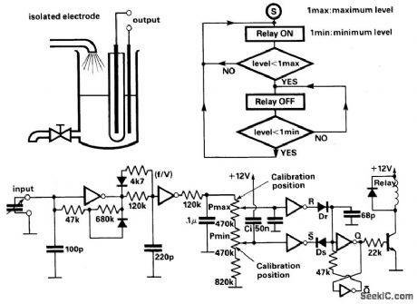
This circuit controls the level of a tank using a bang-bang controlled electrical pump.The actual level of liquid is measured by a capacitive level-meter. The first inverter performs as a capacitance to frequency converter. It is a Schmitt oscillator and its frequency output decreases as the capacitance increases. The second inverter is a monostable which performs as a frequency to voltage converter (f/V). Its output is applied to the maximum and minimum level comparator inputs. Maximum and minimum liquid levels may be set by the potentiometers. The maximum level (1 max) may be preset between the limits: 65 pF less than C (1 max) less than 120 pF. The minimum level is presetable and the limits are: 0 less than C (1 min) less than 25 pF. (View)
View full Circuit Diagram | Comments | Reading(1068)
| Pages:153/312 At 20141142143144145146147148149150151152153154155156157158159160Under 20 |
Circuit Categories
power supply circuit
Amplifier Circuit
Basic Circuit
LED and Light Circuit
Sensor Circuit
Signal Processing
Electrical Equipment Circuit
Control Circuit
Remote Control Circuit
A/D-D/A Converter Circuit
Audio Circuit
Measuring and Test Circuit
Communication Circuit
Computer-Related Circuit
555 Circuit
Automotive Circuit
Repairing Circuit