
Control Circuit
Index 155
HIGH_QUALITY_TONE_CONTROL
Published:2009/6/30 2:45:00 Author:May
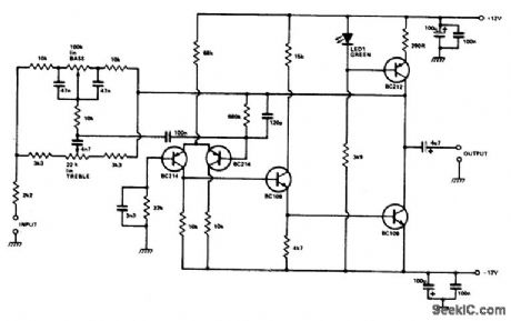
The circuit is based on an inverting op amp using discrete transistors to overcome poor slew rate, fairly high distortion, and high noise problems. The output stage is driven by a con-stant current source, biased by a green LED to provide temperature compensation. With the controls flat, the unit provides unity gain so the stage can be switched in or out. The design is suitable for inputs between 100 mV and 1 V and provides a good overload margin at low distor-tion for the accurate reproduction of transients. The usual screening precautions against hum should be carried out. (View)
View full Circuit Diagram | Comments | Reading(1255)
MICROWAVE_DOPPLER_INTRUSION_ALARM
Published:2009/6/30 2:41:00 Author:May
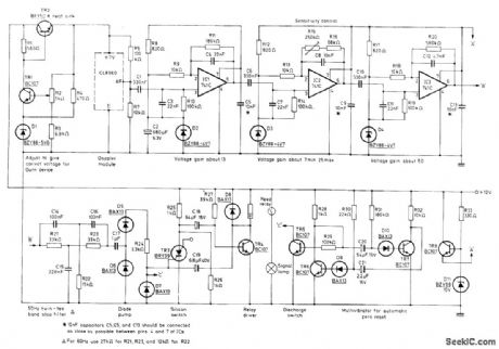
Mullard CL8960 X-band Doppler radar module detects movement of remote target by monitoring Doppler shift in microwave radiation reflected from target. Module consists of Gunn oscillator cavity producing energy to be radiated, mounted alongside mixer cavity that combines reflected energy with sample of oscillator signal. Transmitted frequency is 10.7 GHz. Doppler change is about 31 Hz for relative velocity of 0.45 m/s (1 mph) of relative velocity between object and module, giving AF output for velocities up to 400 mph. Filtered AF is applied through diode pump to trigger of silicon controlled switch TR3 that makes contacts of reed relay open for about 1 s.Relay action is repeated as long as intruder is in monitored area. Report covers circuit operation in detail.-J.E.Saw, Microwave Doppler Intruder Alarms. Mullard, London, 1976, Technical Information 36, TP1570, p 6. (View)
View full Circuit Diagram | Comments | Reading(3609)
LATCHING_ALARM
Published:2009/6/30 2:38:00 Author:May
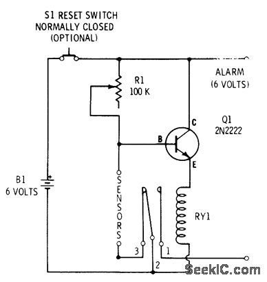
Closed-circuit alarm drawing only 130 μA of standby current from battery is turned on by opening sensor switch or outing wire. Automatic latching contacts on relay prevent burglar or intruder from deactivating alarm by resetting sensor switch, Relay is Radio Shack 275-004. Sensor can be foil strip around window subiect to breakage.-F. M. Mims, Transistor Projects, Vol. 3, Radio Shack, Fort Worth, TX, 1975, p 75-86. (View)
View full Circuit Diagram | Comments | Reading(1734)
15_V_TO_-24_V
Published:2009/6/30 2:36:00 Author:May
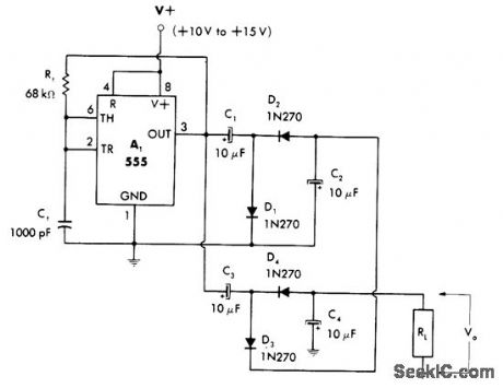
Voltage doubler is used in combination with 555 astable MVBR and two peak-to-peak detectors to give high negative voltages from positive voltage source. Load current capability is about 10 mA. Output drops to about -14.5 V when using supply of +10 V.—W. G. Jung, IC Timer Cookbook, Howard W.Sams, Indianapolis, IN, 1977, p 197-201. (View)
View full Circuit Diagram | Comments | Reading(935)
The switch circuit of light remote control lamp(1)
Published:2011/6/30 21:46:00 Author:zj | Keyword: switch circuit, light remote control lamp(1), 9013
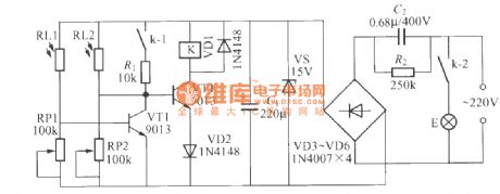
As the diagram shows,it is a switch circuit of light remote control lamp. The remote control can be electric torch or toy laser pointer. Both RL1 and RL2 use MG45 photoresistor.It requires that multiples between the light resistance and the dark resistance are the more the better.You should add shading tubes for them so as to eliminate the interference of environment light when producing. K should use the 12V work voltage. There are two small electromagnetic relays with conversion contacts,like JRX_13F,DC12V etc. (View)
View full Circuit Diagram | Comments | Reading(754)
OUAD_GAIN_CONTROL
Published:2009/6/30 2:20:00 Author:May
Combination of National AM97C11 quad FET and LM324 quad opamp gives tracking gain control having 40-dB range. Bandwidth is 10 kHz minimum, and S/N ratio is better than 70 dB for 4.3-VRMS maximum output. Temperature sensitivity of FET can be reduced by using silicon resistor for opamp feedback resistor R1.- FET Databook, National Semiconductor, Santa Clara, CA, 1977, p 6-39-6-46. (View)
View full Circuit Diagram | Comments | Reading(932)
TONE_DRIVEN_RELAY
Published:2009/6/30 2:13:00 Author:May
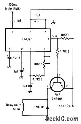
LM567 tone decoder will respond to frequency between 700 and 1500 Hz, determined by setting of 10K pot.When input of 100 mVRMS at preset frequency arrives, output of IC goes low and energizes relay through transistor. Tone can be obtained from audio oscillator or telephone Touch-Tone pad. Relay contacts can be used to turn desired device on or off.-J. A. Sandier, 9 Easy to Build Projects under $9, Modern Electronics, July 1978, p 53-56. (View)
View full Circuit Diagram | Comments | Reading(1647)
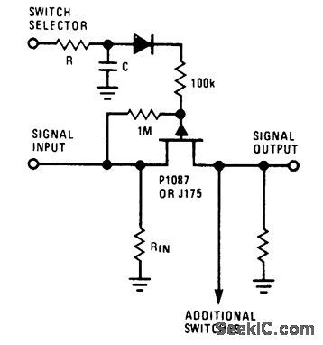
VOLTAGE_CONTROLLED_ATTENUATOR
Published:2009/6/30 2:12:00 Author:May
Used to control low-level audio signals with variable DC voltage of ±3V. Control pot can be remotely located. Highest possible output is equal to input level, occurring when gate bias is set close to pinchoff value. Output is minimum when gate bias is zero.-E, M. Noll, FET Principles, Experiments, and Projects, Howard W. Sams, Indianapolis, IN, 2nd Ed., 1975, p 258-260. (View)
View full Circuit Diagram | Comments | Reading(0)
TWO_OUADRANT_EXPONENTIAL_CONTROL
Published:2009/6/30 2:06:00 Author:May
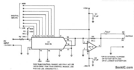
Decibel-weighted control characteristic of Pre-cision Monolithics DAC-76 DIA converter matches natural Ioudness sensitMty of human ear, to provide much greater useful dynamic range for controlling audio Ievel. Control range can be either 72 or 78 dB, depending on pin connections used. 8-bit word control input can be interfaced with standard TTL-compatible microprocessor outputs. To avoid annoying output transients during large or rapid gain changes, use clickless attenuatoriamplifier (also given in application note).-W. Jung and VV.Ritmanich, Audio Applications for the DAC-76 Companding D/A Converter, Precision Mono-Iithics, Santa Clara, CA, 1977, AN-28 p 2. (View)
View full Circuit Diagram | Comments | Reading(973)
LOW_CURRENT_INTRUDER_ALARM
Published:2009/6/30 2:05:00 Author:May
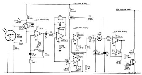
Use of programmable μA776 opamps reduces standby current of infrared alarm to 300 μA, permitting operation from small rechargeable cells. Detector is Mullard RPY86 that responds only to wavelengths above 6 μm, making it immune to sunlight and backgrounds intermittently illuminated by sun. Low-cost mirror is used instead of lens to concentrate infrared radiation on detector. Rd is chosen to make input to first opamp between 2 and 6 V. Circuit energizes alarm relay RL only when incident radiation is changed by movement of intruder in monhored space.- Ceramic Pyroelectric Infrared Detectors, Mullard, London, 1978, Technical Note 79, TP1664, p 8. (View)
View full Circuit Diagram | Comments | Reading(866)
AUDIO_OPERATED_RELAY
Published:2009/6/30 2:05:00 Author:May
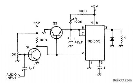
Addition of two general-purpose transistors to 555 timer gives audio-triggered relay that can be used for automatic recording of output of cttannel-monitorlng radio receiver or data from any audio link.Adjustable time delay R keeps control circuit actuated up to 5 s (determined by R and C) to avoid cycling relay during pauses in speech or dropouts in data. Q1 is NPN and Q2 is PNP. Attack time equals very short pullin time of 5-V reed relay K. Adjust 10K input pot just below point at which K pulls in when there is no audio input.-R. Taggart, Sound Operated Relay, 73 Magazine, Qct. 1977, p 114-11 (View)
View full Circuit Diagram | Comments | Reading(0)
DIFFERENTIAL_AMPLIFIE_RCLIPPER
Published:2009/6/30 2:04:00 Author:May
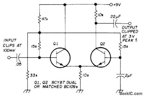
Provides gain as well as precise symmetrical clipping for improving intelligibility of speech fed into radio transmitter. Circuit reduces dynamic range of energy peaks to bdng them closer to average energy level. When inserted in series with microphone, use of clipper gives at least 6-dB increase in effective power. Signals are passed up to certain amplitude but limited above this level.-B. Kirkwood, Principles of Speech Pro-cessing, Ham Radio, Feb. 1975, p 28-34. (View)
View full Circuit Diagram | Comments | Reading(991)
CIRCUIT_BREAKING_ALARM
Published:2009/6/30 2:04:00 Author:May
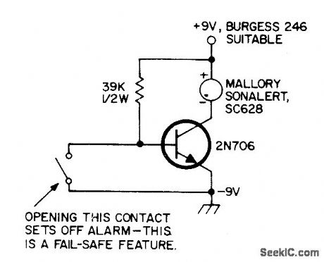
Operates from small 9-V battery, making it independent of AC power failure. Opening of switch or equivalent breaking of foil conductor removes ground from base of transistor, to energize alarm.-Circuits, 73 Magazine, April 1973, p 132. (View)
View full Circuit Diagram | Comments | Reading(825)
WINDOW_FOIL_ALARM
Published:2009/6/30 2:03:00 Author:May
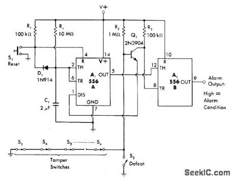
Combination of power-up mono MVBR and latch, using both sections of 556 timer, drives output line high when sensor circuit is opened at door or window switch or by breaking foil on glass. Once alarm is triggered, reclosing of sensor has no effect; S1 must be closed momentarily after restoring sensor circuit to tum alarm off. Circuit includes 22-s power-up delay that prevents triggering of alarm when it is first turned on.-W. G. Jung, IC Timer Cookbook, Howard W. Sams, Indianapolis, IN, 1977, p 231-232. (View)
View full Circuit Diagram | Comments | Reading(1903)
MULTIPLEXED_BURGLAR_ALARM
Published:2009/6/30 1:54:00 Author:May
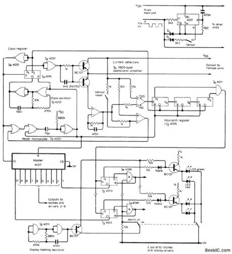
Multiplexing technique provides for detection of state of up to 10 sensors, with immediate identification and location of activated sensor. Only one pair of wires runs from control unit to paralleled remote sensor circuits, one of which is shown at upper right. Each sensor location uses different output from one to zero. Multiplexor circuit is based on 4017 decade counter having 10 individual outputs, to give signals in 10 time slots. Power supply rail is used to reset counter. Clock line is eliminated by switching supply line as square wave. Sensor indication line is eliminated by detecting power supply current drain. Control unit uses oscillator and shift register to generate clocking waveforms. 3900 quad opamp converts sensorline current to logic levels for clocking by master 4017 to control 10 out-put latches and display driver. Two consecutive sensor-open signals are required to activate alarm, minimizing false alarms by interference pulses.-R. J. Chance, Multiplexed Alarm, Wireless World, Nov 1978, p 73-74. (View)
View full Circuit Diagram | Comments | Reading(1648)
BAXANDALL_TONE_CONTROL
Published:2009/6/30 1:53:00 Author:May
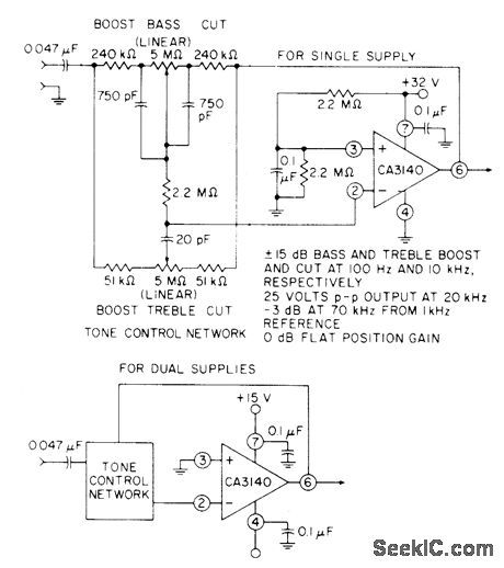
Utilizes high slew rate, high output-voltage capability, and high input impedance of CA3140 bipolar MOS opamp to provide unity gain at midband along with bass and treble boost and cut of ±15dB at 100 and 10,000 Hz. Optional connection for ±15 V supply is shown below.- Circuit Ideas for RCA Linear ICs, RCA Solid State Division, So-merville, NJ, 1977, p 10. (View)
View full Circuit Diagram | Comments | Reading(2186)
FAIL_SAFE_TIMED_ALARM
Published:2009/6/30 1:53:00 Author:May
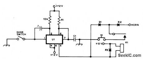
Horn comes on about 30 s after intruder closes door switch by opening car door. Delay is produced by NE555 timer to allow driver to close door after entering or leaving. Thief must keep door open to get leg room for removing equipment under dash. Diodes are 50-PIV 1-A silicon. K1 has 12-V coil. Alarm is set at all times. S1 is normally dosed pushbutton type in door jam. Opening S1 starts timer, and closing it resets alarm.-R. S. Harvey, Junk Box Foils Thieves, QST, Sept. (View)
View full Circuit Diagram | Comments | Reading(1061)
TONE_CONTROL_WITH_HIGH_INPUT_IMPED_ANCE
Published:2009/6/30 1:48:00 Author:May
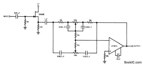
Use of 2N5458 JFET ahead of opampfeedback-type tone control provides high input impedance and low noise characteristics for high-fidelity audio applications,- FET Databook,″ National Semiconductor, Santa Clara、CA、1977,p 6-26-6-36 (View)
View full Circuit Diagram | Comments | Reading(928)
AUTOMATlC_LEVEL_CONTROL
Published:2009/6/30 1:48:00 Author:May
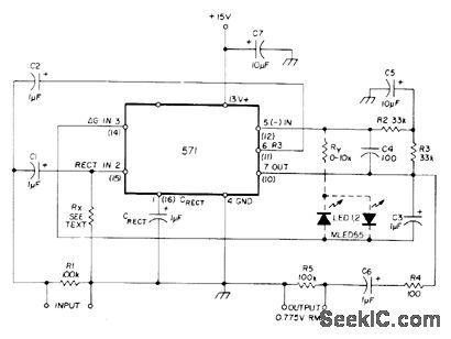
Uses Signetics NE570 or NE571 analog compandor to provide automatic level control for audio signal processing, to give constant high percentage modulation despite varying input levels. Optional resistor Rx varies threshold of level regulation. Widest range of gain control is obtained with Rx, open. When resistor value is Iowered, larger input signal is required for full output.Peak-level dipping with pair of reverse paralleled LEDs controls overshoots on speech by limiting RMS output to 2.2 V P-P. Ry regulates dipped amplitude.-W. G. Jung, Gain Control IC for Audio Signal Processing. Ham Radio, July 1977, p 47-53. (View)
View full Circuit Diagram | Comments | Reading(5015)
OCTAVE_EaUALIZER
Published:2009/6/30 1:47:00 Author:May
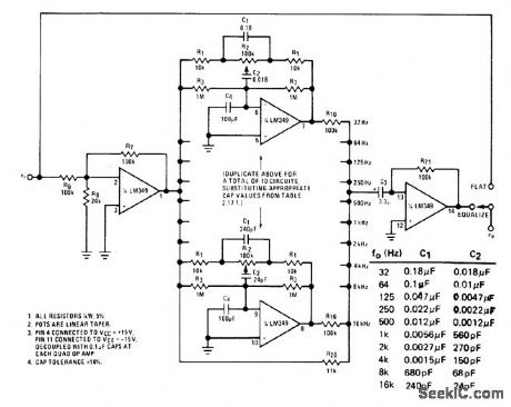
Provides ten bands of tone control, separated by one octave in frequency, with independent adjustment for each.Used to compensate for unwanted amplitudefrequency or phase-frequency characteristics of audio systems. Values of C1 and C2 for each circuit are given in table. With control R2 in flat position, circuit becomes all-pass with unity gain.Moving R2 to full boost gives bandpass characteristic, and moving in other direction to full cut gives bandreject or notch filter. For stereo, identical equalizer is needed for other channel.- Audio Handbook, National Semi-conductor, Santa Clara, CA, 1977, p 2-53-2-59 (View)
View full Circuit Diagram | Comments | Reading(835)
| Pages:155/312 At 20141142143144145146147148149150151152153154155156157158159160Under 20 |
Circuit Categories
power supply circuit
Amplifier Circuit
Basic Circuit
LED and Light Circuit
Sensor Circuit
Signal Processing
Electrical Equipment Circuit
Control Circuit
Remote Control Circuit
A/D-D/A Converter Circuit
Audio Circuit
Measuring and Test Circuit
Communication Circuit
Computer-Related Circuit
555 Circuit
Automotive Circuit
Repairing Circuit