
Control Circuit
Index 159
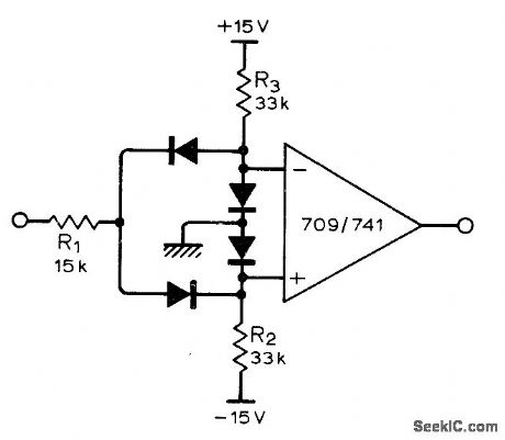
DUAL_LIMITS
Published:2009/6/29 2:30:00 Author:May
View full Circuit Diagram | Comments | Reading(655)
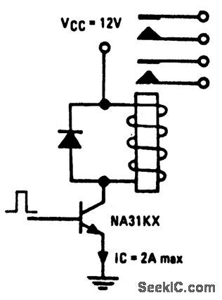
ELECTRONIC_EGG_TIMER
Published:2009/6/29 2:29:00 Author:May
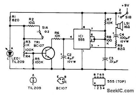
The IC functions as an af multivibrator which is controlled by the external transistor. S1A/B is the on-off toggle switch. (View)
View full Circuit Diagram | Comments | Reading(1100)
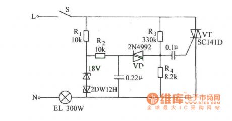
SCR automatic delay light switch circuit diagram
Published:2011/8/1 1:54:00 Author:Ecco | Keyword: SCR , automatic delay , light switch
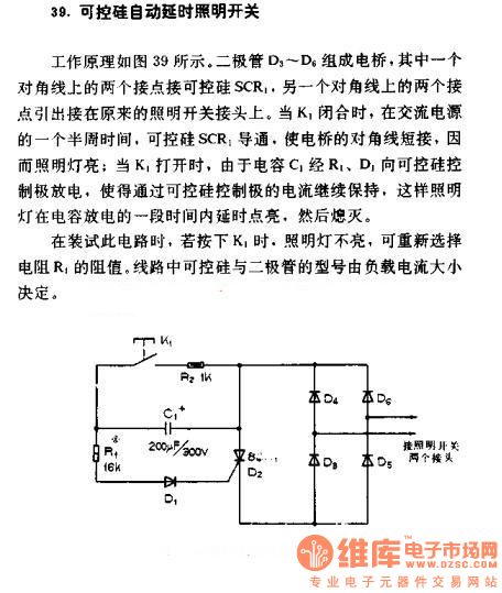
SCR automatic delay light switch
Working principle is shown in Figure 39. The diode D1 ~ D6 make up bridge, the two contacts on one of the diagonalis connected to SCR1, andthe other two contacts on the diagonal leads are connecting to the original light switch. When K1 is closed, in a half week time of AC power, SCR1 turns on, so that the diagonal of the bridge short connected, so lights are bright; when K1 is open, the capacitor C1 discharges through R1, D1 to the SCR system-level, making the current of SCR system-level maintain. So light is turned on in the capacitor discharging delayedtime, then turned off.
When peopleinstall this circuit, if pressing K1, lights off, you can re-select the resistance of resistor R1. The model of SCR and diode circuit determined by the size of the load current. (View)
View full Circuit Diagram | Comments | Reading(1490)
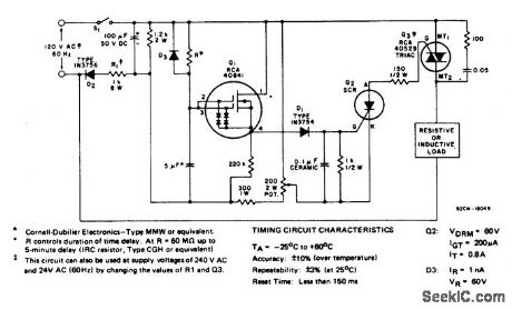
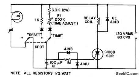
PRECISION_SOLID_STATE_TIME_DELAY_CIRCUIT
Published:2009/6/29 2:28:00 Author:May
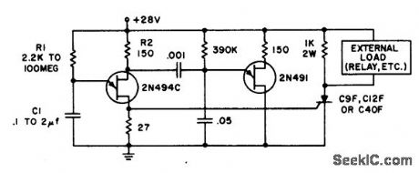
Time delays from 0.3 milliseconds to over three minutes are possible with this circuit without using a tantalum or electrolytic capacitor. The timing interval is initiated by applying power to the circuit. At the end of the timing interval, which is determined by the value of R1C1, the 2N494C fires the controlled rectifier. This places the supply voltage minus about one volt across the load. Load currents are limited only by the rating of the controlled rectifier which is from 1 ampere up to 25 am-peres for the types specified in the circuit. A calibrated potentiometer could be used in place of R1 to permit setting a predetermined time delay after one initial calibration. (View)
View full Circuit Diagram | Comments | Reading(868)
SOLID_STATE_TIMER_FOR_INDUSTRIAL_APPLICATIONS
Published:2009/6/29 2:27:00 Author:May

View full Circuit Diagram | Comments | Reading(993)
Overvoltage charging protection circuit
Published:2011/7/30 10:09:00 Author:Sophia | Keyword: Overvoltage charging protection
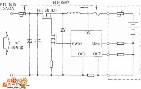
The effect of thermal components and the over-voltage protection components: they can provide current protection against over strong current which may damage the FET and current battery pack. When the polarity is inversed, the thermal components PTC will work to limit overcurrent. the overcurrent is generated by Zener diodes. When over-voltage components provide protection for the overloaded voltage by the components limiting the conduction current to acheive protection. (View)
View full Circuit Diagram | Comments | Reading(689)
Reset_timer_astable_operation
Published:2009/7/24 23:48:00 Author:Jessie
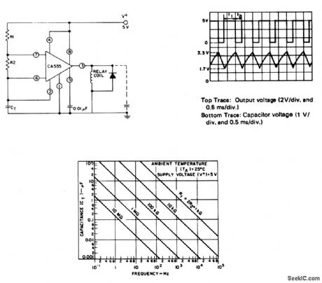
This circuit shows how a CA555 timer can be connected for astable (free-running) operation. Figure 3-13B shows typical waveforms. Figure 3-14C shows free-running frequency versus Rc for various values of R1 + R2 and CT.Notice that the total period is a function of both R1 and R2 as shown by T= 0.693 (R1 +R2)T C and t2= 0.6983 (R2)CT The duty cycle is t2/(t1+t2)= R2/(R1+ 2R2). (View)
View full Circuit Diagram | Comments | Reading(688)
Reset_timer_monostable_operation
Published:2009/7/24 23:45:00 Author:Jessie
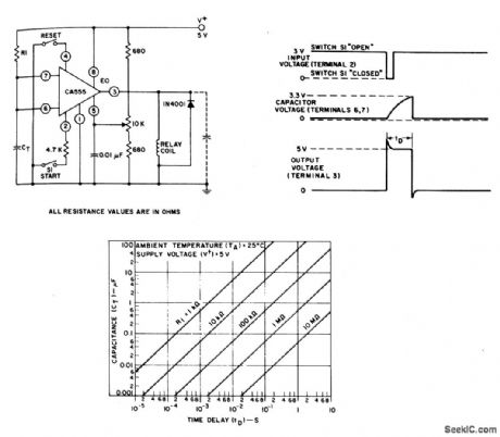
This circuit shows how a CA555 timer can be connected for monostable operation. Figure 3-13B shows typical waveforms. Figure 3-13C shows time delay versus RC for various values of R1 and C1. (View)
View full Circuit Diagram | Comments | Reading(677)
TIME_DELAYED_RELAY_FOR_PATIO_LIGHT,GARAGE_LIGHT,ENLARGER_PHOTOTIMER,ETC
Published:2009/6/29 2:24:00 Author:May
This simple timing circuit cat: delay an output switching function from.01 seconds to about 1 minute. The SCR is triggered by only a few microamps from the timing network R1-C1 to energize the output relay. (View)
View full Circuit Diagram | Comments | Reading(711)
The motor vehicle headlight auto-dimming controller 5
Published:2011/8/1 2:49:00 Author:Ecco | Keyword: motor vehicle, headlight, auto-dimming , controller
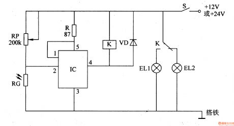
The motor vehicle headlight auto-dimming controller described in the example can automatically change the high beam into low beam at night, it improves the safety of driving at night.The working principle.The vehicle headlight auto-dimming controller circuit consists of photoresistor RG, electronic switch IC, potentiometer Rp, resistor R, the relay K, diode VD and other components, the circuit is shown as the figure 7-5.
Turning on the headlamp control switch S, RG is in a high impedance state due to no light exposure, the pin 2 of IC is in high potential, their internal electronic switch is off, pin 4 outputs high potential, K is in free state, the normally open contact is open, normally closed contact is connected, high beam EL2 is lit.
R chooses 1/2W metal film resistor or carbon film resistors.
RP selects small organic solid potentiometer.
RG uses a photosensitive resistor with light resistancebeing less than or equal to lOkΩ, dark resistancebeing greater than 5OOkΩ.
VD uses lN4007 silicon rectifier diode.
IC selects TWH8751 high-power electronic switching circuit.
K selects a l2V or 24V (supply voltage is according to motor vehicle) small DC relay.
(View)
View full Circuit Diagram | Comments | Reading(1901)
CURRENT_CONTROL_FOR_POWER_SWlTCH
Published:2009/6/29 2:15:00 Author:May
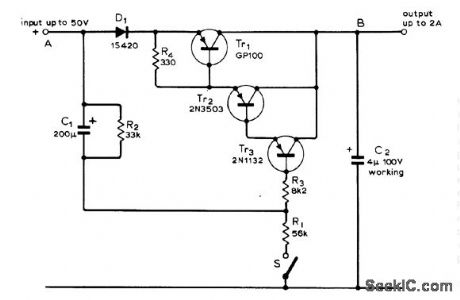
Circuit makes power supply current increase gradually from zero when supply is tumed on, to eliminate transients that sometimes cause alarming loudspeaker thumps in audio systems. Current through silicon power diode D1 is controlled by voltage on C1, which charges up after closing of switch with time constant C1R2R3/(R1 + R2). When switch is opened, rundown of supply curent is controlled by discharge of C1 through R2. Article also covers use of two current control circuits in tandem for handling higher Ioads.-P. J. Briody, Power Supply Delayed Switching, Wireless World, March 1975, p 139-141. (View)
View full Circuit Diagram | Comments | Reading(1138)
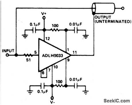
FET_PREAMP_WITH_TONE_CONTROLS
Published:2009/6/29 2:13:00 Author:May
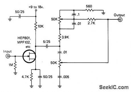
Developed for use with simple 2-W audio amplifier when testing very low-level output circuits and microphones. Will not load circuit to which input is connected. Optional bass/treble tone controls are included.-J. Schultz, An Audio Circuit Breadboarder's Delight, CQ Jan. 1978, p 42 and 75. (View)
View full Circuit Diagram | Comments | Reading(1571)
One_hour_timer_with_manual_controls
Published:2009/7/24 23:30:00 Author:Jessie
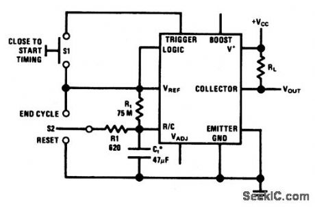
This circuit uses an LM122 connected as a one-hour timer with manual controls for start, reset and cycle-end. S1 starts timing, but has no effect after timing has started. S2 is a center-off switch, which can either end the cycle prematurely or reset to 0 V. A new timing period starts as soon as S2 is released from the reset position. The average charging current through R1 is about 30 nA, so you must pay some attention to the parts layout to prevent stray leakage paths.The suggested timing capacitor has a typical self-time constant of 300 hours, and a guaranteed minimum of 25 hours at + 25℃. (View)
View full Circuit Diagram | Comments | Reading(862)
RELAY_DRIVER_
Published:2009/6/29 1:40:00 Author:May
View full Circuit Diagram | Comments | Reading(850)
Electric fence control circuit 7
Published:2011/8/1 3:04:00 Author:Ecco | Keyword: Electric fence control
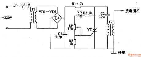
The electric fence control circuit is composed of the power supply circuit and boost circuit, and it is shown in Figure 4-32. Power supply circuit is composed of the power switch S, Fuse FU, isolation power transformer Tl, rectifier diodes VDl-VD4, filter capacitor Cl and limiting resistor Rl. Step-up circuit is composed of the resistors Rl, R2, potentiometer RP, thyristor VT, capacitor C2 and step-up transformer T2. Rl selects the 1/2W metal film resistor; R2, R3 select the 1/4W metal film resistors.
(View)
View full Circuit Diagram | Comments | Reading(5809)
Current_sense_motor_control
Published:2009/7/25 0:17:00 Author:Jessie
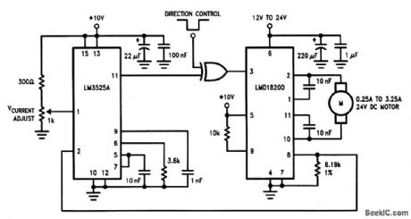
In this circuit, the LM3525 regulating PWM compares the voltage at the current-sense output pin of the LMD18200 with an externally-generated control voltage (VCURRENT ADJUST), and sets the duty cycle of the control signal (from 0 to about 50%) until the motor is running at the desired current level.Switching frequency is about 40 kHz. By inverting the phase of the single control input, the direction of motor rotation can be reversed (View)
View full Circuit Diagram | Comments | Reading(1846)
RPM_LIMIT_ALARM
Published:2009/6/28 23:31:00 Author:May

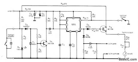
Used with capacitor-discharge ignition system to provide tachometer output along with engine speed control signal. When breaker contacts open, C1 charges and turns Tr1 on, triggering 555 timer used in mono MVBR mode, Resulting positive pulse from 555 fires control SCR through D6 and C6. When contacts dose, D2 isolates C1 to reduce effect of contact bounce. With values shown, for speed limit between 8000 and 9000 rpm, use 0.068 μF for C4 with four-cylinder engine, 0.047 pF for six cylinders, and 0.033 μF for eight cylinders; LED across breaker contacts can be used for setting static timing.-K. Wevill, Trigger Circuit for C.D.l. Systems, Wireless World, Jan. 1978, p 58 (View)
View full Circuit Diagram | Comments | Reading(2775)
WIPER_DELAY_CONTROL
Published:2009/6/28 23:27:00 Author:May
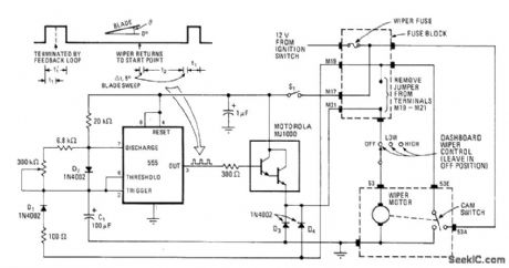
555 timer prvides selsctavel delay tiem between sweeps of wiper blades driven by motor in negative-ground system. Article also gives circuit modification for positive-ground autos. Delay time can ve varied between 0 and 22s. Timer uses feedback signal from cam-operated switch of motor to synchronize delay time with position of wiper blades.-J.Okolwicz, Synchronous Timing Loop Controls Windshield Wiper Delay, Electronics, Nov. 24, 1977, P 115 and 177. (View)
View full Circuit Diagram | Comments | Reading(2375)
The filament lamp dual-channel thyristor lifespan prolonging circuit
Published:2011/7/21 3:17:00 Author:Seven | Keyword: filament lamp, dual-channel thyristor
View full Circuit Diagram | Comments | Reading(750)
The e-bike circuit
Published:2011/7/21 3:07:00 Author:Seven | Keyword: e-bike
View full Circuit Diagram | Comments | Reading(4318)
| Pages:159/312 At 20141142143144145146147148149150151152153154155156157158159160Under 20 |
Circuit Categories
power supply circuit
Amplifier Circuit
Basic Circuit
LED and Light Circuit
Sensor Circuit
Signal Processing
Electrical Equipment Circuit
Control Circuit
Remote Control Circuit
A/D-D/A Converter Circuit
Audio Circuit
Measuring and Test Circuit
Communication Circuit
Computer-Related Circuit
555 Circuit
Automotive Circuit
Repairing Circuit