
Control Circuit
Index 142
ZERO_CROSSING_SWITCH
Published:2009/7/5 22:34:00 Author:May
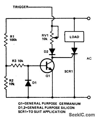
When switching loads with the aid of a thyristor, a large amount of RFI can be generated unless some form of zero crossing switch is used. The circuit shows a simple single transistor zero crossing switch. R1 and R2 act as a potential divider. The potential at their junction is about 10% of the ac voltage. This voltage level is fed, via R3, to the transistor's base. If the voltage at this point is above 0.2, the transistor will conduct, shunting any thyris-tor gate current to ground. When the line po-tential is less than about 2 V, it is possible to trigger the thyristor. The diode D1 is to re-move any negative potential that might cause reverse breakdown. (View)
View full Circuit Diagram | Comments | Reading(4119)
Analysing Kewei Home-Use Hand Drier Circuit
Published:2011/7/29 7:32:00 Author:Robert | Keyword: Analysing, Kewei, Home-Use, Hand Drier
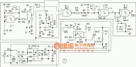
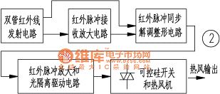
The analysis of hand drier circuit's woking principle.The PCB is the main component of the Kewei hand drier. The author has drew this hand drier's full circuit according to the physical PCB, which is shown in picture 1. And the author has also drew this hand drier's working principle diagram by analysing the circuit in picture 1, which is shown in picture 2.1.The power supply circuit.The Kewei hand drier's power supply uses the commercial power 220V as its power supply. The voltage, which the circuit needs, is the DC low voltage (9V). It firstly uses the capacitor C1 to current limiting and voltage step-down. And then it is rectified by diodes D1~D4 and filtered by the electrolytic capacitor C3. At last it would be regulated by the voltage regulator tube Z1. Then it would output the Vcc (9V) DC voltage to supply the hand drier's each part's power. It is added a capacitor C2, C4 for high-frequency pulses filter and a voltage varistor D5 for peak pulse spike limiting in the power loop circuit. (View)
View full Circuit Diagram | Comments | Reading(671)
FLIP_FLOPS_CONTROL_SAMPLE_AND_HOLD
Published:2009/7/23 22:07:00 Author:Jessie
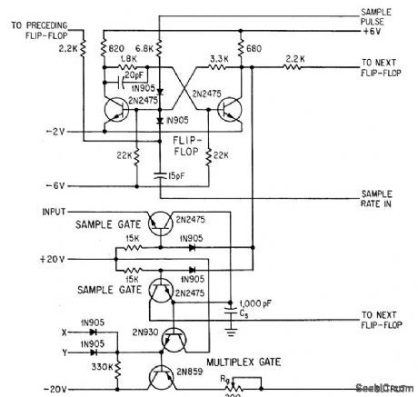
Sampled slices of incoming radar pulse are converted to binary digital form at 10-Mc rate, using flip-flop to connect sample-and- hold capacitor Cs to signal amplifiers. Effective aperture time of sample gate is 20 nsec. Multiplex gate feeds sampled signal values to analog-digital converter at proper time as selected by multiplex counter of system.-A. Hakimoglu and R. D. Kulvin, Sampling Ten Million Words a Second, Electronics, 37:8, p 52-57. (View)
View full Circuit Diagram | Comments | Reading(825)
IONIZATION_ALARM_USING_TRANSISTORS
Published:2009/7/5 22:21:00 Author:May
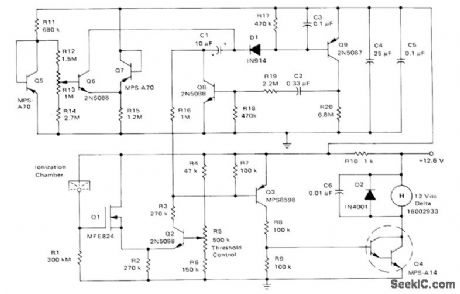
Use of continuous smoke alarm signal rather than beeping horn simplifies transistor circuits needed to trigger fire alarm and low-battery alarm. When high impedance of ionization chamber is lowered by smoke or gas, amplifier Q1-Q2-Q3 supplies 100-μA base current to Darlington Q4 for powering hom continuously as Iong as smoke content exceeds that set by threshold control R5. Low-battery circuit is tdpped at voltage range between 9.8 and 11.2 V, as determined by R13, to energize MVBR Q8-Q9 for driving horn 0.7 s, with 50-s OFF intervals.Battery is chosen to last at least t year while furnishing standby current of about 70μA.-A.Pshaenich, Solid State Gas/Smoke Detector Systems, Motorola, Phoenix, AZ, 1975, AN-735,p 8. (View)
View full Circuit Diagram | Comments | Reading(1419)
INTEGRATED_SOLID_STATE_RELAY
Published:2009/7/5 22:19:00 Author:May
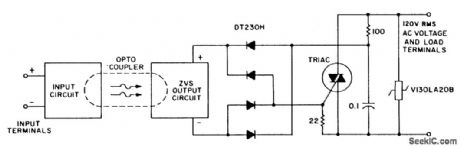
A complete zero-voltage switch solid-state relay contains an input circuit, an output circuit, and the power thyristor. The circuit illustrates a triac power thyristor with snubber circuit and GE-MOVR II Varistor transient over-voltage protection. The 22 ohm resistor shunts di/dt currents, passing through the bridge diode capacitances, from the triac gate, while the 100 ohm resistor limits surge and gate currents to safe levels. Although the circuits illustrated are for 120-V rms operation, relays that operate on 220 V require higher voltage ratings on the MOV, rectifier diodes, triac, and pilot SCR. The voltage divider that senses zero crossing must also be selected to minimize power dissipation in the transistor optisolator circuit for 220-V operation. (View)
View full Circuit Diagram | Comments | Reading(2896)
CLOSED_LOOP,TACHOMETER_FEEDBAGK_CONTROL
Published:2009/7/5 21:54:00 Author:May
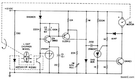
The system utilizes the H21A1 and a chopper disc to provide superior speed regulation when the dynamic characteristics of the motor system and the feedback system are matched to provide stability. The tachometer feedback system illustrated was designed around specific motor/load combinations and may require modification to prevent hunting or oscillation with other combinations. This dc motor control utilizes the optachometer circuit previously shown to control a P.U.T. pulse generator that drives the D44E1 darlington transistor which powers the motor. (View)
View full Circuit Diagram | Comments | Reading(1894)
MOTORT_TACHOMETER_SPEED_CONTROL
Published:2009/7/5 21:53:00 Author:May
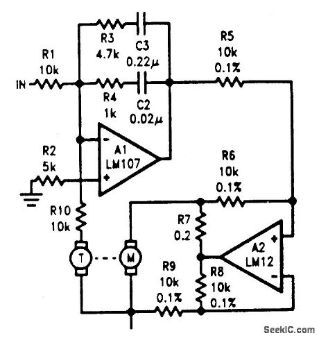
The tachometer, on the same shaft as the dc motor, is simply a generator. It gives a dc output voltage proportional to the speed of the motor. A summing amplifier, A1, controls its output so that the tachometer voltage equals the input voltage, but of opposite sign. With current drive to the motor, phase lag to the tachometer is 90°, before the second order effects come in. Compensation on A1 is designed to give less than 90° phase shift over the range of frequencies where the servo loop goes through unity gain.
Should response time be of less concern, a power op amp could be substituted for A1 to drive the motor directly. Lowering break frequencies of the compensation would, of course, be necessary. The circuit could also be used as a position servo. All that is needed is a voltage indicating the sense and magnitude of the motor shaft displacement from a desired position. This error signal is connected to the input, and the servo works to make it zero. The tachometer is still required to develop a phase-correcting rate signal because the error signal lags the motor drive by 180°. (View)
View full Circuit Diagram | Comments | Reading(1397)
Access_time_tests
Published:2009/7/23 21:58:00 Author:Jessie
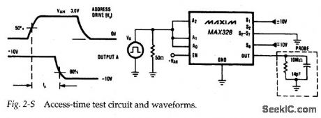
Figure 2-S shows a test circuit for measuring access time versus logic level (high) for the MAX328/29. Notice that a pulse signal is required at the analog inputs.
Typical access time (or transition time) for the MAX328/39M is 1μs maximum, with 1.5μs maximum for the MAX328/29C/E. (View)
View full Circuit Diagram | Comments | Reading(659)
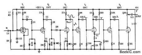
SIGNAL_SEEKING_TUNER
Published:2009/7/23 21:57:00 Author:Jessie
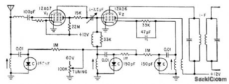
Three silicon diodes, whose capacitances can be varied with externally applied bias voltages, replace conventional tuning capacitors.-J. G. Hammer-slag, Signal-Seeking Auto Radio Uses Semiconductor Tuning, Electronics, 33:30, p 60-62. (View)
View full Circuit Diagram | Comments | Reading(744)
RELAY_TESTER
Published:2009/7/23 21:57:00 Author:Jessie
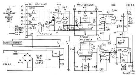
Up to 30 relays ore cycled automatically for minutes or hours to break in contacts and show up early defects. Tester stops and holds for intermittent con tact fault, and lights lamp to identify faulty contact.-F. Trainor, Automatic Relay Tester Delects Infermittents, Electronics, 33:50, 79-81. (View)
View full Circuit Diagram | Comments | Reading(1720)
Data_acquisition_front_end
Published:2009/7/23 22:08:00 Author:Jessie
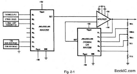
Figure 2-1 shows a typical data0acquisition system using a MAX358 multiplexer.Because the mux is driving a high-impedance input , the error is a function of IC resistance r DS(ON) times the mux leakage current I DS(ON) and the amplifier bias current IBIAS、or:VBRROR=r DS(ON) ×I D(ON) +IBIAS(MAX420) =1.5kΩ×(2nA+30 pA) =3.05-μV maximum error (View)
View full Circuit Diagram | Comments | Reading(708)
41_5050_60AND_60_71_MHz
Published:2009/7/5 21:51:00 Author:May
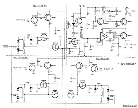
Three Indopendent low-noise VCOs are usedin 41-71 MHz frequency synthesizer, Control voltage is obtained from phase-comparator output of synthesizer. Outputs are chosen by selector switch.Texas Instruments SN72733 wideband amplifier is used for decoupling. Cascade arrangement provides two independent outputs at low impedance.-U. L. Rohde, Modem Design of Frequency Synthesizers, Ham Radio, July 1976, p 10-23. (View)
View full Circuit Diagram | Comments | Reading(1123)
THREE_PHASE_POWER_FACTOR_CONTROLLER
Published:2009/7/5 21:51:00 Author:May
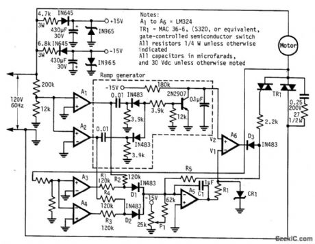
The modified power-factor controller, developed at the Marshall Space Flight Center, employs a phase detector for each of the three phase windings of a delta-connected induction motor. The phase-difference sum is the basis for control. Instabilities of earlier systems are overcome with improved feedback control incorporating a 20Hz bandwidth signal. (View)
View full Circuit Diagram | Comments | Reading(3294)
CURSOR_CONTROL
Published:2009/7/5 21:49:00 Author:May
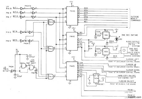
Full software cursor control permits writing anywhere on screen without restrictive top-to-bottom/left-to-right format. System uses 18 of possible 32 ASCII control codes in TV IIsystem having 8K BASIC.Three 7445 BCD-to-decimal decoders operate in 3-line-to-S-line mode wherein pin 12 becomes chip enable. When pin 12 goes low, one of the eight outputs will go low.-R,wright.Utilize ASCII Control Codes!,Kilobaud,Oct.1977,p80-83 (View)
View full Circuit Diagram | Comments | Reading(1629)
OSCILLATOR_CONTROL
Published:2009/7/5 21:39:00 Author:May
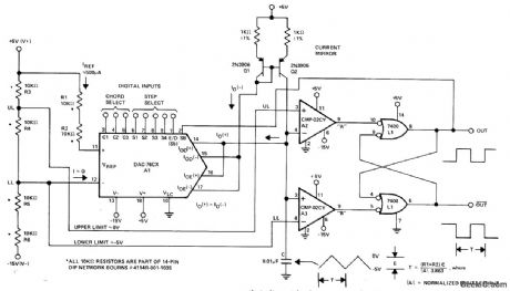
Digital inputs from mioroprocessor to Precision Monolithics DAC-76CX 8-bit companding D/A converter provide 8159:1 frequency range for AF oscillator, from 2.5 to 20,000 Hz. DAC functions as programmable current source that altemately charges and dischatges capacitor between precisely controlled upper and lower limits. Since both limits are derived by dividing power supply volt ages, frequency is independent of changes in supply voltage.Design equations are gtven.-D.Soderquist, Exponential Digitally Controlled Oscillator Using DAC-76, Precision Monolithics, Santa Clara, CA, 1977, AN-20, p 1. (View)
View full Circuit Diagram | Comments | Reading(1063)
Automatic lighting control circuit
Published:2011/7/25 22:37:00 Author:Christina | Keyword: Automatic, lighting control

The core component of the radar type automatic lighting control circuit is the microwave detector module TWH9250. The detection range of this circuit is more than 5m, when someone gets into the detection range, the circuit is triggered, the output port of TWH9250 outputs the low level, the relay K gets power to close, the light turns on, until the person leaves the detection range for 10 seconds, the circuit will reset, the light turns off. The R port of TWH9250 is connected with the photoconductive resistance, so it has minimal resistance value in the day time, the potential of R port is pulled down, the circuit will not work.
(View)
View full Circuit Diagram | Comments | Reading(832)
A_C_ZERO_LOCATOR
Published:2009/7/23 22:09:00 Author:Jessie
Locales zero of a-c voltage within 0.1 microsec for 50-kc input signal. Operation is independent of input signal amplitude between 0.15 and 30 v p-p. Used for accurate measurement of lime interval between given number of cycles of ex ponentially decaying 50.kc signal.-L. Costrell, A.C Zero locator, Electronics, 31:3, p 98-101. (View)
View full Circuit Diagram | Comments | Reading(742)
Homemade 0/12V wireless control switcher circuit
Published:2011/7/25 22:30:00 Author:Christina | Keyword: Homemade, 0/12V, wireless control, switcher circuit
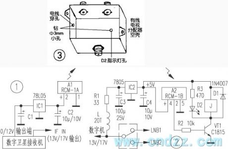
Operating principle: Figure 1 is the circuit of the switcher transmitter part, figure 2 is the circuit of the switcher receiving switch part. In figure 1, when the 0/12V output port of the digital machine has the 12V voltage, it outputs the 5V voltage through the IC1, the A1 radio remote control dedicated transmitter module gets power to operate, the built-in miniature antenna outputs the ultra-high frequency modulation signal.
In the effective receiving range, when the receiving circuit (figure 2) receives the modulating signal, the A2 dedicated receiver module outputs the high level pulse, the transistor VT1 conducts to drive the relay J to finish the switch between the two high frequency heads.
(View)
View full Circuit Diagram | Comments | Reading(684)
Homemade simple remote control switch circuit
Published:2011/7/26 1:25:00 Author:Christina | Keyword: Homemade, simple, remote control, switch circuit
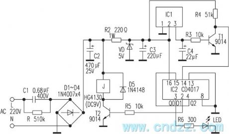
The IC1 is the color TV remote control receiver, pin-1 is the ground port, pin-2 is the +5V power supply port, pin-3 is the signal output port, it has the +3.6V voltage when it does not receive the signal, and it has the 0V voltage when it receives the signal, IC2 is the CD4017 decimal counter / decoder IC.
The 220V AC power supply is reduced, rectified and filted by the circuit to change into the 12V DC voltage that can be used as the operating voltage of the relay, the +12V current is limited by R2 and stabilized by VD to be the +5V current. When the circuit is in the static state, the T1 conducts, Q0=1, the indicator light LED turns on.
(View)
View full Circuit Diagram | Comments | Reading(1779)
Channel_capacitance
Published:2009/7/23 22:06:00 Author:Jessie
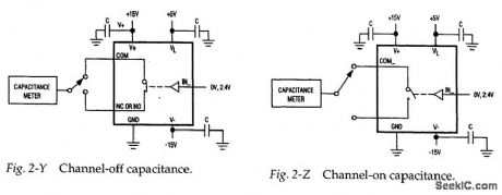
Figures 2-Y and 2-Z show test circuits for measuring channel capacitance with the channel switch open and closed. Typical capacitance is 12 pF with the channel open and 39 pF when the channel is closed. (View)
View full Circuit Diagram | Comments | Reading(618)
| Pages:142/312 At 20141142143144145146147148149150151152153154155156157158159160Under 20 |
Circuit Categories
power supply circuit
Amplifier Circuit
Basic Circuit
LED and Light Circuit
Sensor Circuit
Signal Processing
Electrical Equipment Circuit
Control Circuit
Remote Control Circuit
A/D-D/A Converter Circuit
Audio Circuit
Measuring and Test Circuit
Communication Circuit
Computer-Related Circuit
555 Circuit
Automotive Circuit
Repairing Circuit