
Control Circuit
Index 152
ALARM_GENERATOR
Published:2009/7/1 3:26:00 Author:May
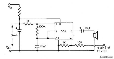
Simple 555 timer generates alarm tone driving small loudspeaker, for use with Cal-Tex CT7001 and other similar digital clocks which do not have internal tone generator. Circuit requires +5 V, but supply can be higher value if suitable dropping resistor is used.-M. S. Robbins, Electronic Clocks and Watches, Howard W. Sams, Indianapolis, IN, 1975,p 91. (View)
View full Circuit Diagram | Comments | Reading(954)
12_h_ALARM
Published:2009/7/1 3:24:00 Author:May
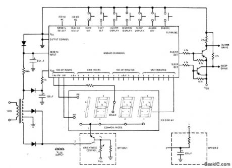
General-purpose digital clock with alarm uses National MM5402 or MM5405 MOS IC to drive 31/2-digit LED display and provide drive for alarm. Brightness control is optional. Sleep output can be used to turn off radio after desired time interval of up to 59 min.- MOS/LSI Databook, National Semiconductor,Santa Clara,CA,1977,p 1-68-1-73. (View)
View full Circuit Diagram | Comments | Reading(4759)
AC_DIGITAL_CLOCK_WITH_STANDBY_BATTERY
Published:2009/7/1 2:43:00 Author:May
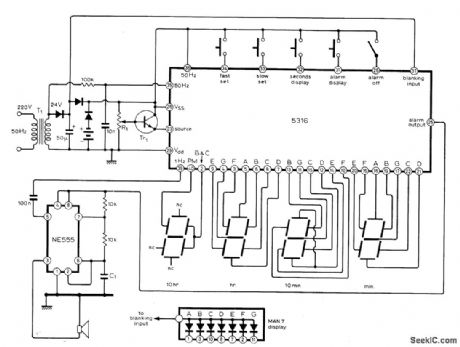
Uses MM5316 alarm-clock IC,originally designed to drive LCD or fluorescent displays,but modified here for LED display Diodes and batteries provide power if AC fails,with blanking of display to extend battery life. Accuracy is poor on batteries but batteries make resetting of time and alarm easier after AC interruption.Alarm uses 555 multivibrator to produce frequency-shfft warble on output tone. Time is set by fast and slow buttons, and alarm is set with same buttons while depressing alarm-display button. Transistor type is not critical.-M. F.Smith, Digital Alarm Clock, Wireless World, Nov. 1976, p 62.
(View)
View full Circuit Diagram | Comments | Reading(2629)
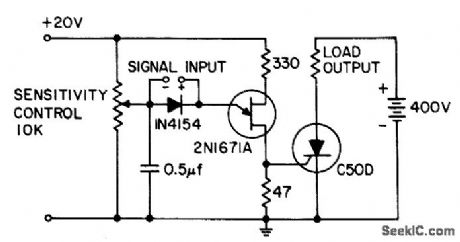
SENSITIVE_A_C_POWER_SWITCH
Published:2009/7/24 4:12:00 Author:Jessie
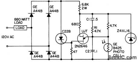
Used to switch load in response to gradually changing signal, as from photocell or thermistor.Provides snap-action switching from full on to full oil, with differential between switching conditions adjustable over wide range by changing C1 and R1.- Transistor Manual, Seventh Edition, General Electric Co., 1964, p 331. (View)
View full Circuit Diagram | Comments | Reading(801)
NR_DIODE_AS_BISTABLE_SWITCH
Published:2009/7/24 4:11:00 Author:Jessie
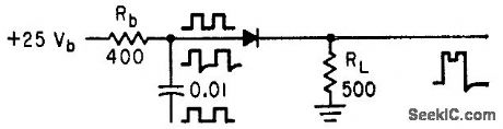
Bonded negative-resistance diode switches to high-current stale on arrival of first pulse. Pulse is shut off before capacitor current through diode falls below negative spike on trailing edge of pulse.-A. P. Schmid, Jr., Negative. Resistance Diode Handles High Power, Electronics, 34:34, p 44-46. (View)
View full Circuit Diagram | Comments | Reading(717)
NEON_LAMP_CAPACITOR_DISCHARGER
Published:2009/7/24 4:10:00 Author:Jessie
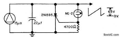
Used to discharge capacitor being charged from constant-current source providing about 15 microamp. Circuit has extremely high impedance until breakdown, then low enough impedance to discharge capacitor to fraction of volt.-R. W. Biddlecomb, High-Current Switch Has High ON/OFF Z Ratio, EEE, 12:2, p 29. (View)
View full Circuit Diagram | Comments | Reading(865)
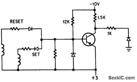
SATURABLE_REACTOR_LATCH
Published:2009/7/24 4:09:00 Author:Jessie
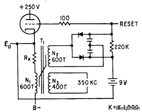
Offers operating simplicity, high speed, and low cost. Transistor model can switch in less than 0.5 microsec. Current through N1, when V1 conducts, saturates core of T1.-W. J. Reap, Simple Latch Circuit Uses Saturable Reactor, Electronics, 33:2, p 66. (View)
View full Circuit Diagram | Comments | Reading(683)
MEMORY_DRIVER_AMPLIFIER
Published:2009/7/24 4:08:00 Author:Jessie
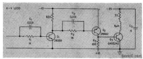
Proves 750-ma current pulse for 8-mkrohenry load, at repetition role of 0.25 Mc. Positive turnoff voltage is automatically applied, with no extra loss in gain or power, by driving pnp transistor Q3 with npn transistor Q2.-J. S. Ronne, Computer Switching With High-Power Transistors, Electronics, 33:10, p 44-47. (View)
View full Circuit Diagram | Comments | Reading(701)
GATE_TURNOFF_D_C_CIRCUIT_BREAKER
Published:2009/7/24 4:07:00 Author:Jessie
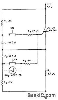
Closing on switch discharges C1 into gate to initiate turn-on. Closing off switch discharges C2 out of pate, opening power circuit.-J. W. Motto, Jr., Switching Circuits Using the Gate Turnoff Controlled Rectifier, EEE, 13:3, p 52-55. (View)
View full Circuit Diagram | Comments | Reading(736)
IGNITRON_SHORTS_SPARK_GAP
Published:2009/7/24 4:07:00 Author:Jessie
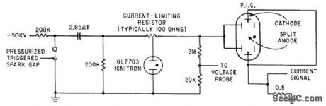
Used for continuous production of plasma in mirror-geometry magnetic Geld of Philips ionization gage. Ignitron shorts spark gap about 100 microsec aftet discharge begins. Ionization gage (PIG) receives positive potential at peak of externally applied magnetic fold by dosing of triggered spark gap.-M. F. Wolff, Plasma Engineering-Part 1 : Generating and Heating Plasma, Electronics, 34:24, p 47-53. (View)
View full Circuit Diagram | Comments | Reading(1607)
TEMPORARY_MEMORY
Published:2009/7/24 4:17:00 Author:Jessie
Arrangement using Esaki or tunnel diode is equivalent to bistable flip-flop. Used in 24-channel pulse code modulation system.-T. Kojima and M. Watanabe, When You're Second, You Try Harder, Electronics, 38:25, p 81-89. (View)
View full Circuit Diagram | Comments | Reading(786)
SENSITIVE_D_C_POWER_SWITCH
Published:2009/7/24 4:17:00 Author:Jessie
Stays on after being triggered, to give latching action. Power input is 2.5 microwatts, power output is 44,000, and power gain is 92 db.- Transistor Manual, Seventh Edition, General Electric Co., 1964, p 331. (View)
View full Circuit Diagram | Comments | Reading(681)
AUDIO_SWITCH
Published:2009/7/24 4:16:00 Author:Jessie
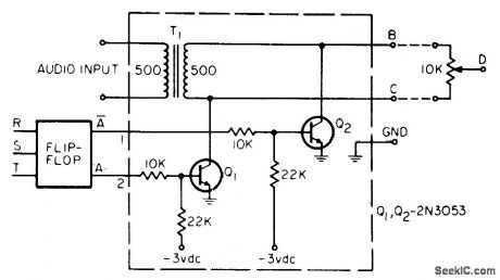
Switches audio signal on and off under control of flip-flop. With potentiometer across output, phase can be reversed. With two of these switches connected to same flip-flop, and each excited by different audio signal, potentiometer connected between B outputs will provide signal from wiper to ground that alternates from one audio signal to other as flip-flop changes state. Pot setting determines relative amplitudes of two signals. Can be used to generate a-f shift-keying signals.-F. Stevens, Audio On-Off, Phase-Reversing Switch, EEE,14:6, p 91-92. (View)
View full Circuit Diagram | Comments | Reading(1051)
HIGH_POWER_SCR_STATIC_SWITCH
Published:2009/7/24 4:16:00 Author:Jessie
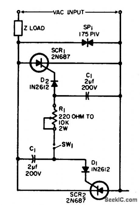
Prevents burning of switch or relay contact when switching large inductive loads. Switch contacts here carry only trigger current for silicon controlled rectifiers. If desired, output power can be varied by changing time constant R1-C1 to control scr firing angle. Will switch primary of transformer having 4,200 v-a secondary load.-J. A. Moraites, High Power AC Static Switch, EEE, 12:8, p 71. (View)
View full Circuit Diagram | Comments | Reading(1512)
1_MILLIMICROSEC_SPARK_GAP_SWITCH
Published:2009/7/24 4:15:00 Author:Jessie
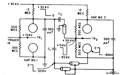
Spark gaps are mounted so ultraviolent to diction from gaps that ire earlier in 111-gap operating sequence irradiate succeeding gaps. Intense radiation front earlier gaps reduces statistical firing delay, or jitter, of succeeding gaps. Breakdown of gap is further speeded by connecting low-potential end of gap to trigger source with short length of cable and blocking capacitor, which in turn is grounded by similar cable.-H. B. McFarlane, Spark Gaps for Fast-High Voltage Switching, Electronics, 32:31, p 72-73. (View)
View full Circuit Diagram | Comments | Reading(742)
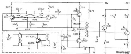
SEQUENTIAL_SWITCHING
Published:2009/7/24 4:14:00 Author:Jessie
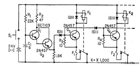
Shock-resistant design releases number of solenoid-operated mechanical locks at 10-millisec intervals. Single-stroke ramp generator Q1 starts sequence when dosing of initiation switch S1 discharges C1. Q2 reduces loading on timing circuit R1-C1 when large base currents are drawn. Ramp is sufficiently linear to provide adequate timing accuracy for eight operations.-D. H. Thompson and D. Simpson, Time-Sequence Switch, Electronics, 33:28, p 64. (View)
View full Circuit Diagram | Comments | Reading(988)
LIGHT_BEAM_COUPLING
Published:2009/7/24 4:14:00 Author:Jessie
Gallium arsenide light source and silicon photodetector prevent interaction between drive circuit and output of binary switch.-E. L. Bonin, Light-Coupled Semiconductor Switch for Low-Level Multiplexing, Electronics, 38:3, p 54-59. (View)
View full Circuit Diagram | Comments | Reading(616)
SOLID_STATE_DPDT_SWITCH
Published:2009/7/24 4:22:00 Author:Jessie
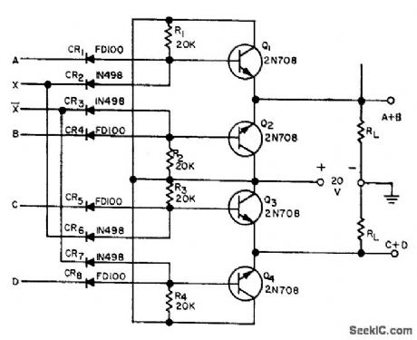
Eight diodes and four transistors connected as shown give same action as double-pole double-throw relay.-R. C. Going, Solid-State DPDT Relay, EEE, 11:10, p 26-27. (View)
View full Circuit Diagram | Comments | Reading(2132)
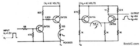
FAST_SWITCHING_OF_D_C_POWER
Published:2009/7/24 4:21:00 Author:Jessie
Power transistor 06 switches 20 W d-c through 15-ohm load R3 under control of scr Q1, which in turn is controlled by start-stop pulse amplifiers Q2 and Q3, and multivibrator Q4-Q5. Switching rote can be up to 700 cps.-J. E. Roberts, Controlled Recliners for Fost Power Switching, Electronics, 35:17, p 58-59. (View)
View full Circuit Diagram | Comments | Reading(638)
HYBRID_SWITCH_PROVIDES_1500_V_PULSE
Published:2009/7/24 4:19:00 Author:Jessie
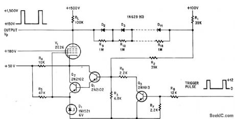
Trigger pulse at 12 V saturates Q3, voltage across R3 drops below level of tenor D1, and Q1 and Q2 turn off, making V1 stop conducting. Anode voltage of V1 then rises to 1,500-V supply value until input pulse is removed.-R. E. Thomas, 1,500-Volt Hybrid Switch has Low On Impedance, Electronics, 37:22, p 74-75. (View)
View full Circuit Diagram | Comments | Reading(652)
| Pages:152/312 At 20141142143144145146147148149150151152153154155156157158159160Under 20 |
Circuit Categories
power supply circuit
Amplifier Circuit
Basic Circuit
LED and Light Circuit
Sensor Circuit
Signal Processing
Electrical Equipment Circuit
Control Circuit
Remote Control Circuit
A/D-D/A Converter Circuit
Audio Circuit
Measuring and Test Circuit
Communication Circuit
Computer-Related Circuit
555 Circuit
Automotive Circuit
Repairing Circuit