
Control Circuit
Index 160
The DC motor control circuit
Published:2011/7/21 2:40:00 Author:Seven | Keyword: DC motor, control circuit

View full Circuit Diagram | Comments | Reading(707)
The necessary control unit circuit
Published:2011/7/21 2:41:00 Author:Seven | Keyword: control unit
View full Circuit Diagram | Comments | Reading(827)
PROTECTION_FOR_ORP_TUNING
Published:2009/6/28 22:41:00 Author:May
Simple resistive SWR bridge provides dummy load, relative power output indicator, and safe method of tuning transmitter without destroying transistors because of mismatched load. Input divider R1-R4 has total resistance of 50 ohms, using 1/2-W composition resistors, for dissipating transmitter output when S1 is in TUNE position. M1 indicates relative power applied to this load. Antenna is connected through Transmatch, and antenna tuner is adjusted for minimum deflection or lowest SWR. RE isolates transmitter from antenna. With S1 in OPERATE position, M1 indicates relative power output into antenna.-A S. Woodhull, Simplified Output Metering Protects QRP Transmitters, QST, April 1977, p 57. (View)
View full Circuit Diagram | Comments | Reading(2483)
5_V_CROWBAR
Published:2009/6/28 22:39:00 Author:May
View full Circuit Diagram | Comments | Reading(1)
FAST_ACTING_POWER_SUPPLY_PROTECTION
Published:2009/6/28 22:38:00 Author:May
When using a regulated power supply to reduce a supply voltage, there is always the danger that component failure in the power supply might lead to a severe overvoltage condition across the load. To cope with overvoltage situations, the circuit is designed to protect the load underovervoltage conditions. Component values given are for a 20 V supply with regulated output at 12 V. The zener diode can be changed according to whatever voltage is to be the maximum. If the voltage at the regulator output rises to 13 V or above, the zener diode breaks down and triggers the thyristor which shorts out the supply line and blows the main fuse. (View)
View full Circuit Diagram | Comments | Reading(888)
OVERVOLTAGE_PROTECTION_FOR_LOGIC
Published:2009/6/28 22:37:00 Author:May
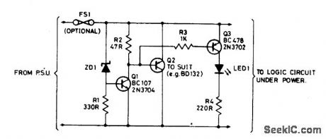
Zener diode ZD1 senses the supply, and the should the supply rise above 6 V, Q1 will turn on. In turn, Q2 conducts clamping the rail. Subsequent events depend on the source supply. It will either shut down, go into current limit or blow its supply fuse. None of these will damage TTL chips. The rating of Q2 depends on the source supply, and whether it will be required to operate continuously in the event of failure. Its current rating has to be in excess of the source supply. (View)
View full Circuit Diagram | Comments | Reading(1038)
OVERVOLTAGE_PROTECTION_WITH_AUTOMATIC_RESET
Published:2009/6/28 22:35:00 Author:May
View full Circuit Diagram | Comments | Reading(929)
HIGH_SPEED_WARNING
Published:2009/6/28 22:31:00 Author:May

Audible alarm tone generator drives waming Ioudspeaker to supplement 2-digit speed display that can be set to trip when vehicle speed exceeds 55-mph legal limit. Engine speed signal is taken from primary of spark coil. Switch in transmission activates circuit only when car is in high gear. All functions are performed by sections of LM2900 quad Norton opamp. A1 amplifies and regulates sparlocoil signal. A2 converts signal frequency to voltage proportional to engine speed. A3 compares speed voltage with reference voltage and turns on output transistor at set speed. A4 generates audible tone. Circuit components must be adjusted for number of cylinders, gear and axle ratios, tire size, etc. 10-μF capacitor connectea to A3 can be increased to prevent triggering of alarm when increasing speed mo-mentarily while passing another car.- Linear Applications, Vol. 2, National Semiconductor, Santa Clara, CA 1976, LB-33. (View)
View full Circuit Diagram | Comments | Reading(854)
POWER_PROTECTION_CIRCUIT
Published:2009/6/28 22:30:00 Author:May
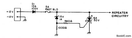
To safeguard portable, emergency power repeaters from reverse or excessive voltage, D1 prevents incorrect polarity damage, and zener voltage determines the maximum voltage that will reach the rest of the circuitry.Use fast blowing fuse rated greater than the SCR current rating. (View)
View full Circuit Diagram | Comments | Reading(763)
ELECTRONIC_CROWBAR_FOR_AC_OR_DC_LINES
Published:2009/6/28 22:29:00 Author:May


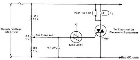
For positive protection ofelectrical or electronic equipment, use this against excessive supply voltage. Due to improper switching, wiring, short circuits, or failure of reg-ulators, an electronic crowbar circuit can quickly place a short circuit across the power lines, thereby dropping the voltage across the protected device to near zero and blowing a fuse. The triac and SBS are both bilateral devices, the circuit is equally useful on ac or dc supply lines. With the values shown for R1, R2, and R3, the crowbar operating point can be adjusted over the range of 60 to 120 volts dc or 42 to 84 volts ac. The resistor values can be changed to cover a different range of supply voltages. The voltage rating of the triac must be greater than the highest operating point as set by R2. I1 is a low power incandescent lamp with a voltage rating equal to the supply voltage. It may be used to check the set point and operation of the unit by opening the test switch and adjusting the input or set point to fire the SBS. An alarm unit such as the Mallory Sonalert may be connected across the fuse to provide an audible indication of crowbar action.(This circuit may not act on short, infrequent power line transients). (View)
View full Circuit Diagram | Comments | Reading(1694)
ANTENNA_POSITION_CONTBOL
Published:2009/6/28 22:03:00 Author:May
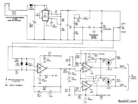
IC logic provides automatic brake release and poshitive povsition control for commercial Ham-M antenna rotator Regulated power supply drives bridge haing position-sensing pot R8 in rotator and R9 in control box When antenna is in desired position, wiper voltages of pots are equal.When R9 is set to new position, voltage difference is amplified by error amplifier U2. Comparators U3 and U4 determine rotation direction needed for rebalance and delivet logic circuits to timing circuit (also given in article) that drives motor and brake release relays.Timer prevents jamming of circuit by operator error.-P. Zander, Automatic Position Control for the HAM-M Rotator, Ham Radio, May 1977, p 42-45. (View)
View full Circuit Diagram | Comments | Reading(2562)
ELECTRIC_VEHICLE_CONTROL
Published:2009/6/28 21:45:00 Author:May


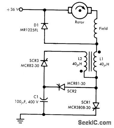
SCR1 is used in combination with Jones chopper to provide smooth acceleration of golf cart or other electric vehicle operating from 36-V on-board storage battery. Normal running current of 2-hp 36-V series-wound DC motor is 60 A, with up to 300 A required for starting vehicle up hill. Chopper and its control maintain high average motor current while limiting peak current by increas-ing chopping frequency from normal 125 Hz to as high as 500 Hz when high torque is required.-T. Malarkey, You Need Precision SCR Chopper Control, New Motorola Semiconduc-tors for Industry, Motorola, Phoenix, AZ, Vol, 2, No. 1, 1975. (View)
View full Circuit Diagram | Comments | Reading(1563)
HEADLIGHTS_ON_ALARM
Published:2009/6/28 21:31:00 Author:May
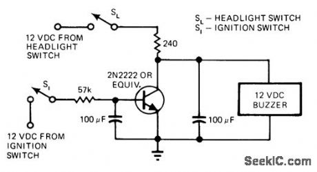
Designed for cars in which headlight switch is nongrounding type, providing 12 V when dosed. When both light and ignition switches are closed, transistor is saturated and there is no voltage drop across it to drive buzzer. If ignition switch is open while lights are on, transistor bias is removed so transistor is effectively open and full 12 V is applied to buzzer through 240-ohm resistor until lights are turned off.-R. E. Hartzell, Jr., Detector Warns You When Headlights Are Left On, EDN Magazine, Nov. 20, 1975, p 160. (View)
View full Circuit Diagram | Comments | Reading(910)
PRECISION_FREQUENCY_COUNTER(~1_MHz_MAXIMUM)
Published:2009/6/28 21:30:00 Author:May
View full Circuit Diagram | Comments | Reading(690)
LED_BRIGHTNESS_CONTROL
Published:2009/6/28 21:14:00 Author:May
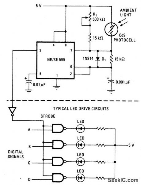
Circuit NotesThe brightness of LED display is varied timing resistor to boost the timer's maximum by using a photocell in place of one timing duty cycle. The result is a brighter display in resistor in a 555 timer, and bypassing the other sunlight and a fainter one in the dark. (View)
View full Circuit Diagram | Comments | Reading(882)
1AUDIO_POWER_METER
Published:2009/6/28 21:07:00 Author:Jessie
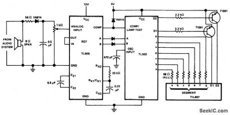
View full Circuit Diagram | Comments | Reading(1519)
AUDIO_POWER_METER
Published:2009/6/28 21:06:00 Author:Jessie
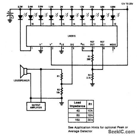
View full Circuit Diagram | Comments | Reading(1557)
EXTENDED_RANGE_VU_METER(DOT_MODE)
Published:2009/6/28 21:05:00 Author:Jessie
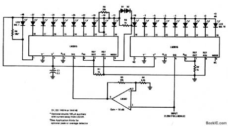
View full Circuit Diagram | Comments | Reading(2617)
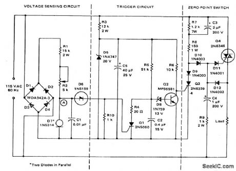
UNIVERSAL_MOTOR_SPEED_CONTROL
Published:2009/6/26 3:46:00 Author:Jessie
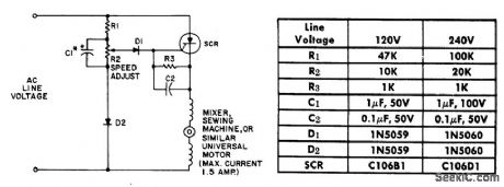
The resistor capacitor network R1-R2-C1 provides a ramop-type reference voltage superimposed on top of a dc volatage adjustable with the speed-setting potentiometer R2.This reference voltage appearing at the wiper of R2 is balanced against the residual counter emf of the motor through the SCR gate.As the motor slows down due to heavy loading,its couter emf falls,and the reference ramp triggers the SCR earlier in the ac cycle.More voltage is thereby applied to the motor causing it to pick up speed again.Performance with the C106 SCR is particularly good because the low trigger current requirements of this device allow use of a flat top reference voltage, which provides good feedback gain and close speed regulation. (View)
View full Circuit Diagram | Comments | Reading(2713)
FOUR_POSITION_MOTOR_SWITCH
Published:2009/6/26 2:25:00 Author:May
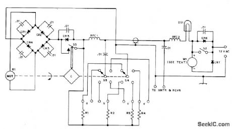
Single RF feed line also carries DC for 3-V permanent magnet DC motor B1 atop antenna tower, driving S3 and S4 for remote switching to antennas a, b, c, and d. Diagram shows switches set for feed to antenna a, with no drive applied to Bt since cam C has opened microswitch S5. CR5 and CR6 are now connected in series with opposite polarity, so neither positive nor negative halfwaves from 12-VAC supply can drive motor. If S2 is closed, poshive halfwaves start B1. Once started, motor runs until cam opens S5; if S2 has not yet been released, motor continues running on positive and negative halfwaves. Diode bridge CR1-CR4 makes motor rotate in only one direction for either drive polarity. If S2 is released, before S5 opens, motor stops. 6-V 1-A lamp DS1 comes on dimly when S2 is closed and brightens when S5 closes. If S2 is released now, B1 drives to next position and stops. If S2 is held down, switching continues. Meter M1 and CR7 identify position of switch. R1-R4 in range of 1K to 10K, are chosen to give 1/4, 1/2, 3/4, and full deflection of meter. Motor drives switch through 2860:1 reduction gears taken from alarm clock. All diodes are 50-PIV 1-A silicon such as 1N4001.-U.H.Lammers, A Remote Antenna Switch, QST,Aug.1974, p 41-43. (View)
View full Circuit Diagram | Comments | Reading(1048)
| Pages:160/312 At 20141142143144145146147148149150151152153154155156157158159160Under 20 |
Circuit Categories
power supply circuit
Amplifier Circuit
Basic Circuit
LED and Light Circuit
Sensor Circuit
Signal Processing
Electrical Equipment Circuit
Control Circuit
Remote Control Circuit
A/D-D/A Converter Circuit
Audio Circuit
Measuring and Test Circuit
Communication Circuit
Computer-Related Circuit
555 Circuit
Automotive Circuit
Repairing Circuit