
Control Circuit
Index 148
WIRE_CUTTING_ALARM
Published:2009/7/2 3:17:00 Author:May
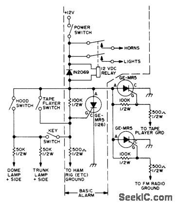
SCR normally acts as open circuit in series with 12-VDC alarm relay because grid is made negative by voltage divider consisting of 100K in series with500 ohms. If ground on 500-ohm resistor is re-moved, as by removal of tape player or CB set from car by thief, gate becomes more posltive and SCR conducts, to energize relay, sound hom, and make headlights shine brightly. Ad-ditional triggering SCRs or alarm switches can be added as shown outside of dashed area for basic alarm.-A. Szablak, Another Burglar Alarm, 73 Magazine, May 1974, p 45-46. (View)
View full Circuit Diagram | Comments | Reading(870)
Linearized_platinum_RTD_signal_conditioner
Published:2009/7/24 2:32:00 Author:Jessie
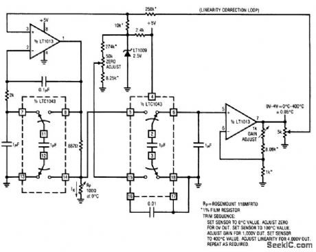
Fig. 13-19 This circuit provides complete linearized signal conditioning for a platinum RTD (Rosemount 118MFRTD). To calibrate, substitute a precision decade box (General Radio 1432k) for Rp Set the box to the 0℃ value (100.00Ω) and adjust the offset trim (50 kΩ zero adjust) for a 0.00-V output. Next, set the decade box for a 140℃ output (154.26Ω) and adjust the gain trim (1 kΩ) for a 1.400-V output reading. Finally, set the box to 249.00Ω (400.00℃) and trim the linearity adjustment (5 kΩ) for a 4.000-V output. Repeat this sequence until all three points are fixed. The total error should be ±0.05℃ over the entire range for a normal100.00-Ω (0℃) sensor. Linear Technology. Linear Applications Handbook, 1990, p AN3-6. (View)
View full Circuit Diagram | Comments | Reading(1368)
OPEN_CIRCUIT_ALARM
Published:2009/7/2 3:15:00 Author:May
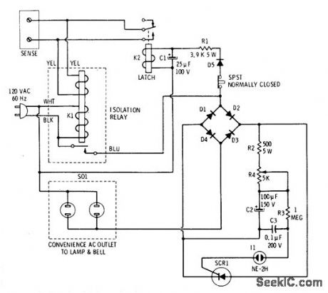
Closing of door or window switch sensor or closing of normally open panic-button switch at bedside and other strategic locations in home trips alarm that sounds loud bell and flashes bright light on and off. Sensor shorts control winding of K1, allow-ing K1 to drop out and apply line voltage to alarm circuit. One AC path is through D5 which rectifies AC for energizing DC latch relay K2 to short sensor lines even though initiating sensor has opened. Simultaneously, AC is applied to diode bridge having SCR between DC legs. C2 starts charging through R2 and R4, and C3 charges through R3. When voltage across C3 reaches about 9O VDC it fires neon and C3 dis-charges into gate of SCR. FuII Iine voltage is then applied to Iamp and bell plugged ;nto Ioad outlets. When C2 drops below holding current, SCR tums off during next AC cycle and Ioad goes off until neon fires again. Setting of 5K pot R4 gives range of 15-80 flashes and hom pulses per seeond. To stop alarm, open SPST switch momentarily.-R. F. Graf and G. J. Whalen, 'The Build-It Book of Safety Electronics, How-ard W Sams, Indianapolis, IN, 1976, p 75-8O. (View)
View full Circuit Diagram | Comments | Reading(1241)
Offset_linearization_for_type_S_thermocouple
Published:2009/7/24 2:30:00 Author:Jessie
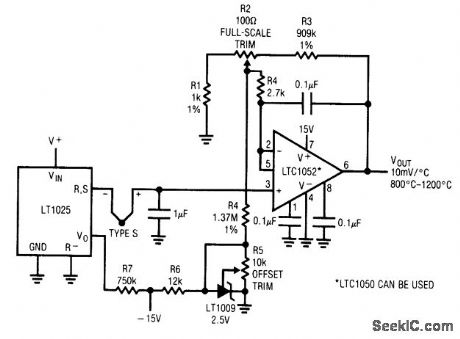
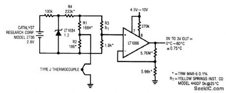
Fig. 13-18 In this circuit, the LT1025 provides cold-junction compensation and the LTC chopper-stabilized amplifier is used for low drift. The type-S thermocouple output slope varies greatly with temperature (at 25℃, the output is 6℃, with an 11μV/℃ slope at 1000℃). This circuit linearizes the output and provides 3℃ accuracy over the indicated output range of 800 to 1200℃. To calibrate, trim R2for a Vout of 1.669 with a Vin, of 0.000 mV. Then, trim R2 for a Vout of 9.998 with a temperature of 1000℃ or for a Vin (+input) of 9.585 mV. (View)
View full Circuit Diagram | Comments | Reading(1579)
INTRUDER_ALARM
Published:2009/7/2 3:05:00 Author:May
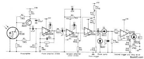
Input is from Mullard RPY86 infrared detector responding to wave-lengths above 6 μm, making it immune to sun-light and backgrounds intermittently illumi-nated by sun. Output signal is produced only when ihcident radiation is changed by movement of intruder in monitored space. Mirrors rather than lenses concentrate incident radia-tion on detector because mirrors do not require high-quality surface finish. Preamp is followed by two amplifier stages, with R10 varying gain of second stage between 10 and 100. Band-width is 0.3-10 Hz. First trigger, having thresh-old of about 1 V, drives second trigger through diode pump to energize alarm relay when in-truder is present.- Ceramic Pyroelectric In-frared Detectors, Mullard, London, 1978, Tech-nical Note 79, TP1664, p 8. (View)
View full Circuit Diagram | Comments | Reading(1979)
Oven_temperature_controller
Published:2009/7/24 2:46:00 Author:Jessie
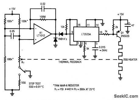
Pig. 13-27 This circuit shows a precision temperature controller for a small-component oven. When power is applied, the thermistor (a negative TC device) is at a high value. A1saturates positive. This forces the LT3525A switching regulator output low, biasing Q1. As the heater warms, the thermistor value decreases. When the inputs balance, A1comes out of saturation and the LT3525A pulse-width modulates the heater via Al, completing a feedback path. The 2-kHz pulse-width-modulated heater power is much faster than the thermal-loop response and the oven sees an even, continuous heat flow. Linear Technology Linear Applications Handbook, 1990, p. AN5-1. (View)
View full Circuit Diagram | Comments | Reading(1827)
PULSED_HORN_ALARM
Published:2009/7/2 3:01:00 Author:May
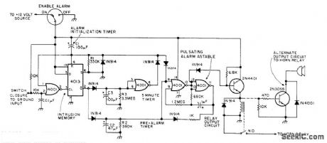
Two CMOS packages incorporate multiple time delays to improve convenience and effectiveness of auto intrusion alarm. R1C1 gives 30-s delay for arming alarm after it is turned on by switch concealed inside car, to let driver get out of car. R2C2 gives 15-s delay before alarm sounds after door is opened, to allow driver to get back in car again and disable alarm. R3C3 turns off alarm in 300 s and resets alarm system for next intrusion. Car horn is pulsed 60 times per minute, so alarm would not be confused with stuck horn. Article tells how circuit works and gives detailed instruc-tions for instailation and connection to door and trunk switches.-G. Hinkle, Give the Hamburglar Heart Failure, 73Magazine, Feb. 1977, p 36-37. (View)
View full Circuit Diagram | Comments | Reading(924)
Alternate_relative_humidity_sensor
Published:2009/7/24 2:35:00 Author:Jessie
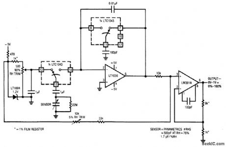
Fig. 13-21 This circuit is an alternate to that of Fig. 13-20. The circuit requires two op amps, but only one LTC1043 package. Calibration is the same as for Fig. 13-20. Linear Technology Lineal Applications Handbook 1990 p AN3-8.
(View)
View full Circuit Diagram | Comments | Reading(731)
Platinum_RTD_signal_conditioner_with_curvature_correction
Published:2009/7/24 2:39:00 Author:Jessie
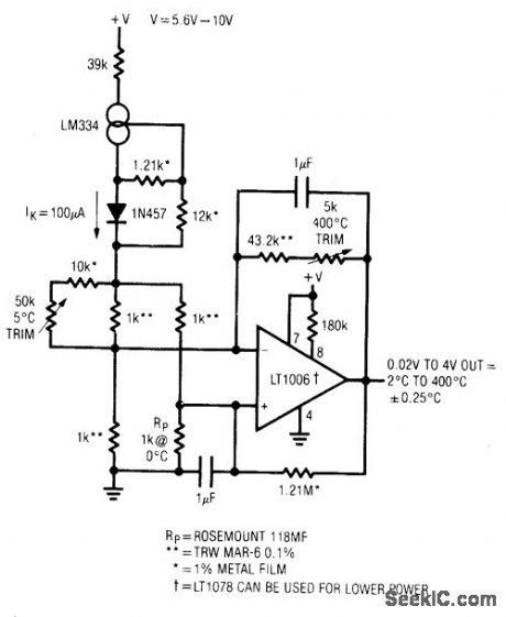
Fig.13-23 This simple circuit provides an accuracy of 0.25℃ over 2℃ to 400℃ sensed range, Note that one side of sensor Rp is grounded to minimize noise problems. To calibrate, substitute a precision decade box(General Radio 1432)for Rp. Set the box to the 5℃ value(1019.9Ω)and adjust the 5℃ trim for 0.05 V at the LT1006. Next, set the box for the 400℃ value(2599.9Ω)and adjust the 400℃ trim for a 4.000-V output, Repeat this procedure until both points are fixed. The resistance values given are for a nominal 1000.0-Ω(0℃)sensor. Sensors that deviate from this nominal value can be used by factoring In the deviation from 1000.0Ω Linear Technology. Linear Application Handbook 1990, AN23-1. (View)
View full Circuit Diagram | Comments | Reading(962)
Linearized_platinum_RTD_sensor_with_ratiometric_output
Published:2009/7/24 2:37:00 Author:Jessie
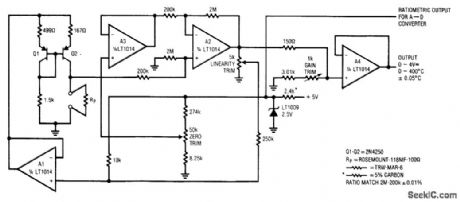
Fig. 13-22 This circuit is an alternate to that of Fig. 13-19, but it also provides a ratiometric output for A/D converters (and does not require switched-capacitor ICs). Calibration is the same as for Fig. 13-19. Linear Technology Linear Applications Handbook 1990 p Ahl1-1. (View)
View full Circuit Diagram | Comments | Reading(667)
EXPONENTIAL_DECAY_LOAD
Published:2009/7/24 2:45:00 Author:Jessie
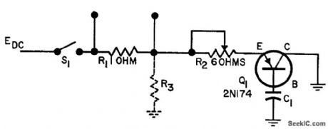
Used in place of a capacitor when large load with expo nential decay is required. R1 provides means for monitoring current on cro. Article gives component values for wide range of decay limes, from 50 millisec to 1 sec, with initial discharge currents of 6.3 to 21.5 amp. Source voltage is 28 V.-B. Bever and L. Snyder, Transient Load With Exponential Decay, EEE, 10:10, p 31. (View)
View full Circuit Diagram | Comments | Reading(754)
High_noise_rejection_thermometer
Published:2009/7/24 2:44:00 Author:Jessie
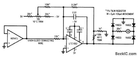
Pig. 13-26 This circuit makes it possible to transmit the temperature sensor output directly over an unshielded wire, with high noise immunity. Once calibrated with sensor and connecting wires in place, the circuit provides a typical ±2.0℃ accuracy-even in high-noise environments. To calibrate the thermometer, place the op-amp sensor in a +1℃ environment, and trim the 10℃ adjustment for an appropriate meter indication. Next, place the sensor in a +40℃ environment, and trim the 40℃ adjustment. Repeat the procedure until both points are fixed. Linear Technology Linear Applications Handbook 1990 p AN9-17. (View)
View full Circuit Diagram | Comments | Reading(732)
RADAR_RANGE_TESTER
Published:2009/7/24 2:44:00 Author:Jessie
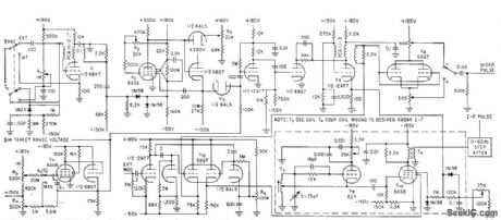
Dynamic target simulator independently generates time-delayed fixed or moving target pulses for target rates above mach 3, for testing range accuracy of airborne automatic-tracking radar.-O. B. Mitchell, Simulator Tests Radar Trucking Systems, Electronics, 34:8, p 51-53. (View)
View full Circuit Diagram | Comments | Reading(848)
Thermocouple_to_frequency_converter
Published:2009/7/24 2:43:00 Author:Jessie
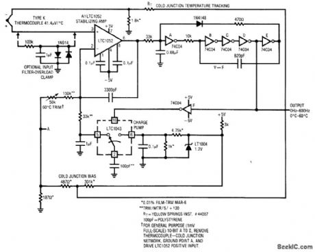
Fig. 13-25 This circuit also provides temperature-to-frequency conversion, but it uses the popular type-K thermocouple as a sensor (instead of a temperature sensor as does the circuit of Fig. 13-24). To calibrate it, place the thermocouple in a 60℃ environment, and adjust the 50-kΩ potentiometer for 600 Hz output. Note that beyond 60℃, the cold-junction network departs from the thermocouple's response and causes output errors to increase rapidly. Linear technology Linear Applications Handbook 1990, p. AN7-3. (View)
View full Circuit Diagram | Comments | Reading(1593)
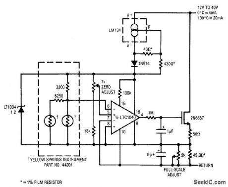
Temperature_to_frequency_converter
Published:2009/7/24 2:41:00 Author:Jessie

Fig. 13-24 This circuit provides a simple way to convert the current output of an LM334 temperature sensor to a corresponding output frequency. To calibrate it, place the LM334 in a 0℃environment and set the 0℃ adjustment for 0 Hz at the TTL output. Next, put the LM334 in a 100℃ environment and set the 100℃ adjust control for a 1-kHz output. Repeat this procedure until both points are fixed. This circuit has a stable 0.1℃ resolution with ±1.0℃ accuracy. Linear Technology, Linear Applications Handbook, 1990, p. AN7-2. (View)
View full Circuit Diagram | Comments | Reading(3)
JOYSTICK_CONTROL
Published:2009/7/2 1:45:00 Author:May
Mechanically conttolled voltage source generates two independent con-trol voltages, proportional to stick position, to serve as one of controls for elaborate sound synthesizer used for generating wide variety of musical and other sounds. Three-part article describes circuit operation and gives all other circuits used in synthesizer.-T. Ort and D. W. ThomasElectronic Sound Synthesizer, wireless world Part 3-Oct 1973.p 485-490(Part1-Aug 1973.p 366-372;Part 2-Sept.1973.p429-434) (View)
View full Circuit Diagram | Comments | Reading(957)
Oven_temperature_controller_with_RTD_sensor
Published:2009/7/24 2:57:00 Author:Jessie
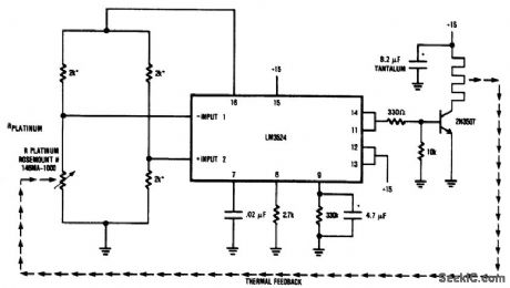
Fig. 13-34 This circuit is similar to that of Fig, 13-27, except that the sensor is a platinum RTD. If the sensor is in close thermal contact with the heater, the circuit will easily control to 0.1℃ stability over widely varying ambient temperatures. National Semiconductor, Linear Applicatrions Handbook 1991 p 858.
(View)
View full Circuit Diagram | Comments | Reading(1621)
Temperature_to_pulse_width_converter
Published:2009/7/24 2:54:00 Author:Jessie
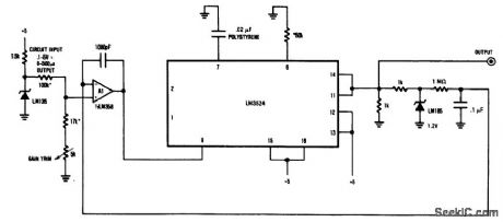
Fig. 13-33 This circuit uses an LM3524 pulse-width modulator to convert the output of an LM135 temperature transducer into a pulse width that can be measured by a digital system (such as a microprocessor-based data-acquisition system). Although the example uses the temperature transducer as the input, the circuit will convert any 0.1- to 5-V input applied to the 100-kΩ resistor into a 0- to 500-ms output pulse width with 0. 1 % linearity. The overall temperature-to-pulse-width scale factor is adjusted with the 5-kΩ gain-trim potentiometer. The oscillator output pulse at pin 3 of the LM3524 (not shown) occurs just before the pins 11/14 output pulse and it can be used to reset counters or other digital circuits. National Semiconductor Linear Applications Handbook, 1991, p 857. (View)
View full Circuit Diagram | Comments | Reading(948)
Battery_operated_thermocouple_with_cold_junction_compensation
Published:2009/7/24 2:53:00 Author:Jessie
Pig. 13-32 This cold-junction thermocouple signal conditioner does not require any trim, and provides an accuracy of ±0.75℃ over the indicated range (0 to 60℃). Current consumption is about 125μA. Using the specified battery life will approach 10 y ears. Linear Technology Linear Applications Handbook, 1990 p AN23-2. (View)
View full Circuit Diagram | Comments | Reading(972)
Thermocouple_signal_conditioner_with_cold_junction_compensation
Published:2009/7/24 2:51:00 Author:Jessie
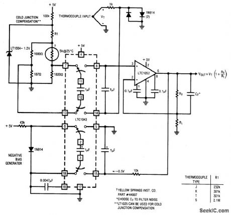
Fig. 13-31 This circuit shows a 5-V powered thermocouple signal conditioner. Cold-junction compensation is included, and the circuit allows one leg of the thermocouple to be grounded (for noise considerations). The table gives proper values for R1 for various standard thermocouples. Output scaling can be set by RF/R1 to whatever slope is desirable. Cold-junction compensation holds within ±1℃ over 0o to 60℃. Linear Technology, Linear Applications Handbook 1990, p AN 11-5. (View)
View full Circuit Diagram | Comments | Reading(1127)
| Pages:148/312 At 20141142143144145146147148149150151152153154155156157158159160Under 20 |
Circuit Categories
power supply circuit
Amplifier Circuit
Basic Circuit
LED and Light Circuit
Sensor Circuit
Signal Processing
Electrical Equipment Circuit
Control Circuit
Remote Control Circuit
A/D-D/A Converter Circuit
Audio Circuit
Measuring and Test Circuit
Communication Circuit
Computer-Related Circuit
555 Circuit
Automotive Circuit
Repairing Circuit