
Control Circuit
Index 157
AF_LEVEL_CONTROL
Published:2009/6/29 23:47:00 Author:May
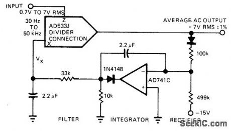
AD533J analog multiplier used in its divide mode provides measure of automatic level control to compensate for variations in loudness occurring from micro-phone to microphone in publicaddress system.Divider output is first rectified and compared with -15 V reference, Difference is then integrated and fed into denominator of divider-connected AD533J as control signal Vx. Average AC output is held within 1% of 7 V.-R. Frantz, An-alog Multipliers-New IC Versions Manipulate Real-World Phenomena with Ease, EDN Magazine, Sept. 5, 1977, p 125-129. (View)
View full Circuit Diagram | Comments | Reading(834)
CLICKLESS_LEVEL_CONTROL_ATTENUATOR
Published:2009/6/29 23:47:00 Author:May
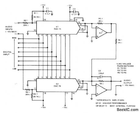
Uses two Precision Monolithics DAC-76 D/A converters to eliminate gain-change transients while providing exponential control of audio signal level. Maximum (all 1s) gain is unity from either input to output, while differential input to output gain is +6 dB. Control range is 78 dB.-W. Jung and W. Ritmanich, Audio Appli-cations for the DAC.76 Companding D/A Converter, Precision Monolithics, Santa Clara, CA, 1977, AN-28, p 4 (View)
View full Circuit Diagram | Comments | Reading(758)
COMPRESSOR_LIM_ITER
Published:2009/6/29 23:45:00 Author:May
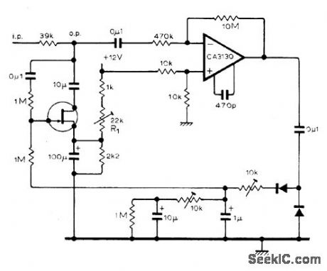
Developed for use with microphone in public-address systems.Bandwidth is 15 Hz to 25 kHz. R1 sets threshold voltage and compression law. Output of CA3130 inverting opamp is made as large as possible before being applied to rectifier and low-pass filter, to minimize effects of diode nonlinearities and capacitor leakage. Low-pass filter gives required fast attack time of about 500 ps and long decay time of about 1 min.-M. B.Taylor, Speech Compressor/Limiter, Wireless World, May 1977, p 80. (View)
View full Circuit Diagram | Comments | Reading(799)
SPEECH_PROCESSOR
Published:2009/6/29 23:44:00 Author:May
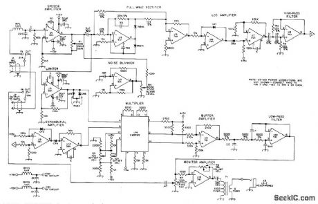
Can improve signal strength and intelligibility of voice signals up to 6 dB without unpleasant changes in fidelity.Used between microphone and input of AM or SSB transmitter. Based on separation of signal envelope from constant-amplitude carrier that together make up voice signal. After Iogamp U6 separates components of speech waveform, envelope is filtered out by cative RC high-pass filter U8 having 50.Hz cutoff, with exactly unity gain above cutoff. Filtered signal goes to ex-ponential amplifier U9-U10 and is then multi-plied by correct sign information in U14. Sign information is obtained by hard-Iimiting input voice signal with diode clipper CRS-CR6. Re-sulting square-wave output is multiplied by sig-nal from UJT in U14. Processed signal goes to transmitter input through low-pass filter U12 having sharp cutoff above 3 kHz to eliminate unwanted high-frequency energy. CR1-CR4 are 1N914 or other matched silicon diodes. T1 is 250-mW audio transformer. Article gives con-struction and adjustment details.-J. E. Kauf-mann and G. E. Kopec, A Homomorphic Speech Compressor, QST, March 1976, p 33-37. (View)
View full Circuit Diagram | Comments | Reading(0)
EXPANDER
Published:2009/6/29 23:40:00 Author:May
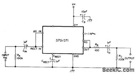
Uses Signetics dual-channel compandor IC; 571 has lower inherent distortion and higher supply voltage range (6-24 V) than 571 (6-18 V). Values shown are for 15-V supply with either IC. Gain through expander is 1.43 VIN, where VIN is average input voltage. Unity gain occurs at RMS input level of 0.775V, or 0 dBm in 600-ohm systems.-W.G.Jung, Gain Control IC for Audio Signal Processing, Ham Radio, July 1977, p 47-53. (View)
View full Circuit Diagram | Comments | Reading(2032)
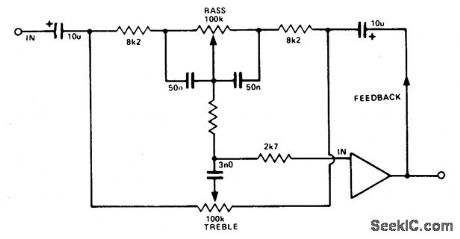
SWITCHING_CLICK_SUPPRESSOR
Published:2009/6/29 23:39:00 Author:May
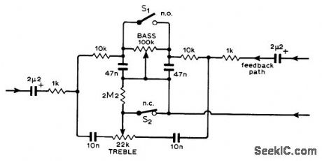
Correction network shown can be inserted in audio channel of mixing console without producing transients or level changes. Although Baxandall network is shown, switching technique is applicable to other filters. With S1 normally open and S2 normally closed, circuit operation is normal. If switch positions are simultaneously reversed, response remains flat regardless of positions of bass and treble pots, centerfrequency gain remains unchanged, and phase shift is unchanged. There is then no transient interruption of AF signals. Switching clicks cannot occur because there is no direct current in the network.-J. S. Wilson, Click-Free Switch-ing forAudio Filters, Wireless World, Jan. 1975, p12. (View)
View full Circuit Diagram | Comments | Reading(752)
LINEAR_1_4_VOLUME_EXPANDER
Published:2009/6/29 23:39:00 Author:May
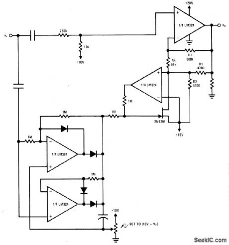
Gain varies automatically with strength of input signal, being lowest for weak signals. Resistors R3 and R4 modify linear control curve to give log curve desired foraudio systems. Overall gain of circuit is about 0 dB at midrange of expansion. Lower pair of LM324 quad opamp sections function as full-wave precision linear peak detector. For stereo, only upper part of circuit needs to be duplicated for second channel.- Linear Appli-cations, Vol. 2, National Semiconductor, Santa Clara, CA, 1976 AN-129 p 7. (View)
View full Circuit Diagram | Comments | Reading(822)
CLIPPER
Published:2009/6/29 23:38:00 Author:May
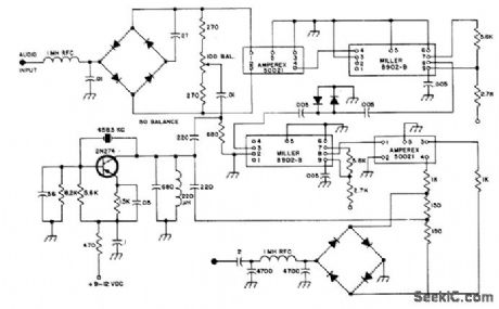
Provides speech clipping at BF level for SSB transmitters. Based on use of two Amperex 455-kHz IF crystal filters having 4-kHz rated bandwidth, in place of costly conventional sideband filters. Miller 8902-B IF amplifier module simplifies wiring. Diode balanced modulator at upper left can use individual 1N63 or 1N914 diodes, or FICA CA.3019 hex diode array that also provides diodes for RF clipper. Audio input can be taken from speech compressor of re celver, or separate audio amplifier can be added to boost AF level. Same diode types are used in product detector for final SSB signal, lower right, which is diode ring demodulator taking in jection voltage from carrier oscillator. Article tells how pin 8 on IF module (not connected in-temally) is bridged to solder line between link output of last IF transformer and AM detector diode, and gives other construction details.-J.J. Schultz, Inexpensive RF Speech Clipper, 73 Magazine, Sept. 1974, p 61-64 and 66. (View)
View full Circuit Diagram | Comments | Reading(1)
BAXENDALL_TONE_CONTROL_CIRCUIT
Published:2009/6/29 23:22:00 Author:May
View full Circuit Diagram | Comments | Reading(616)
PASSIVE_BASS_&_TREBLE_TONE_CONTROL
Published:2009/6/29 23:22:00 Author:May
View full Circuit Diagram | Comments | Reading(725)
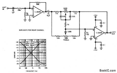
ACTIVE_BASS_&_TREBLE_TONE_CONTROL_WITH_BUFFER
Published:2009/6/29 23:20:00 Author:May
View full Circuit Diagram | Comments | Reading(1248)
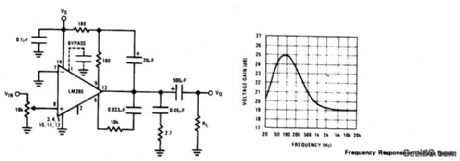
AMPLIFIER_WITH_BASS_BOOST
Published:2009/6/29 23:20:00 Author:May
View full Circuit Diagram | Comments | Reading(1144)
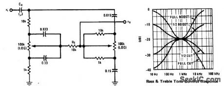
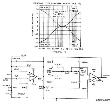
IC_PREAMPLIFIER_WITH_TONE_CONTROL
Published:2009/6/29 23:19:00 Author:May
View full Circuit Diagram | Comments | Reading(845)
THREE_CHANNEL_TONE_CONTROL
Published:2009/6/29 23:18:00 Author:May
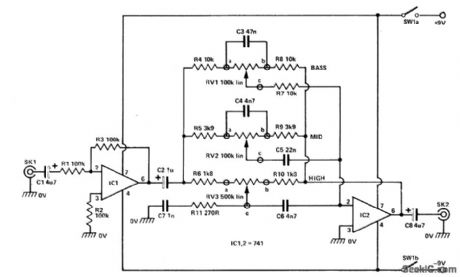
The input signal is fed via SKI to the first active stage built around IC1. Configured as a noninverting amplifier whose gain is set by the ratio of R3 and RI. In this case, the gain is set at unity. This initial stage is required to isolate the following stage from any loading effects. The output from IC1 is fed via three frequency shaping networks to IC2. The three networks built around RV1, RV2, and RV3 are also in-cluded in the feedback path of IC2, another inverting op amp stage. The components as-sociated with the three variable resistors are chosen to give the required frequency control. (View)
View full Circuit Diagram | Comments | Reading(831)
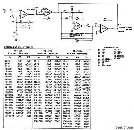
EQUALIZER
Published:2009/6/29 23:17:00 Author:May
View full Circuit Diagram | Comments | Reading(0)
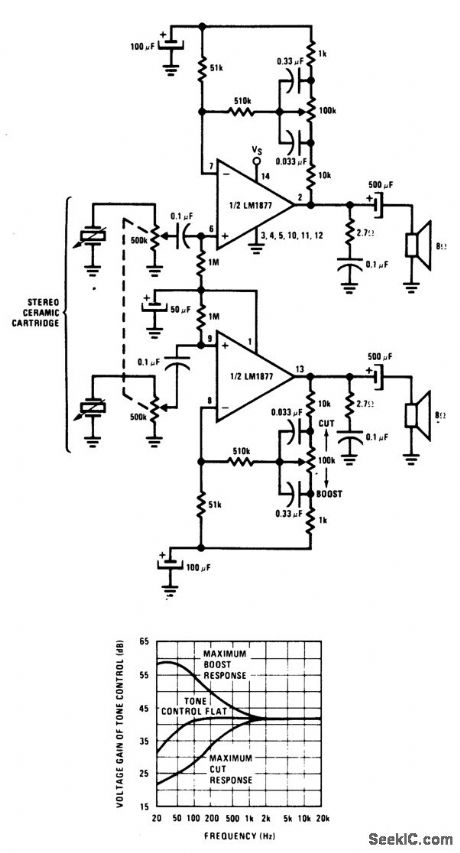
STEREO_PHONOGRAPH_AMPLIFIER_WITH_BASS_TONE_CONTROL
Published:2009/6/29 23:16:00 Author:May
View full Circuit Diagram | Comments | Reading(820)
NICAD_CHARGE_CONTROL
Published:2009/6/29 23:04:00 Author:May
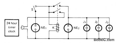
Prevents doublecharging if someone forgets to turn off 24-h time clock after recommended 16-h charge period. Nicad devices with built-in chargers are plugged into jacks J1-J3, and timer dial is advanced until clock switch is triggered. Neon lamp NE1 should now come on. Momentary pushbutton switch S is pushed to energize relay K and start charge, When timer goes off, K releases to end chatge.-M. Katz, Battery Charge Monitor, CQ, July 1976, p 27. (View)
View full Circuit Diagram | Comments | Reading(677)
The Circuit of TV Steady Pressure Protection Used in Countryside
Published:2011/5/6 1:39:00 Author:May | Keyword: TV Steady Pressure Protection
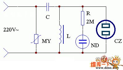
The application of this set is shown in the diagram. As the voltage of transmission network in the countryside is not very stable now, you can homemade a simple AC magnetic saturation regulator device. You can merge a varister MY in the input end of AC constant voltage regulator. It can protect the TV from overvoltage and let TV work more stable. Using the AC voltage regulator in thunderstorm days can protect the TV from striking by lightning.
(View)
View full Circuit Diagram | Comments | Reading(659)
CURRENT_CONTROLLED_SWTCHING
Published:2009/6/29 22:20:00 Author:May
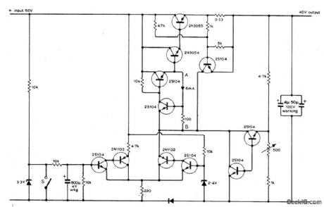
Addition of current control to 40-V regulated power supply for audio amplifier elimin ates switch-on transients that sometimes cause lilming loudspeaker thumps. Switch S,which can be either relay or third pole on standard ON/OFF switch of amplifier,is opened to initiats charging of 800-μF capacitor that allows gradual buildup of output current ,Similar transient suppression occurs when switch is closed to initiate current run-down as set is turned off,Run-up rundown times are a few seconds each,Article also tives simpler current control circuit suitable for use with unregulated supplies,-P.J.Briody,Power Supply Delayed Switching,Wirless World, March 1975, p 139-141 (View)
View full Circuit Diagram | Comments | Reading(968)
SOFTWARE_CONTROL
Published:2009/6/29 21:52:00 Author:May


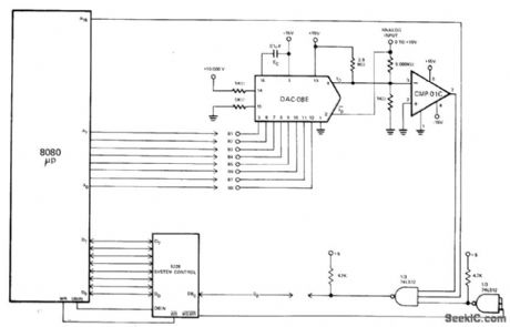
Innovative software for Intel 8080A microprocessor eliminates need for peripheral isolation devices when using Precision Monolithics DAC-08E D/A converter and CMP-01C comparator for 8-bit A/D conversion. Technique can easily be expanded to 10-bit or 12-bit conversions and adapted to other microprocessors. Logic of microprocessor replaces conventional successive-approximation register. 8 lowest-order address bits control data bit input to DAC, using software given in article.—W. Ritmanich and W. Freeman, Software Controlled Analog to Digital Conversion Using DAC-08 and the 8080A Microprocessor, Precision Monolithics, Santa Clara, CA, 1977, AN-22 p 3. (View)
View full Circuit Diagram | Comments | Reading(754)
| Pages:157/312 At 20141142143144145146147148149150151152153154155156157158159160Under 20 |
Circuit Categories
power supply circuit
Amplifier Circuit
Basic Circuit
LED and Light Circuit
Sensor Circuit
Signal Processing
Electrical Equipment Circuit
Control Circuit
Remote Control Circuit
A/D-D/A Converter Circuit
Audio Circuit
Measuring and Test Circuit
Communication Circuit
Computer-Related Circuit
555 Circuit
Automotive Circuit
Repairing Circuit