
Control Circuit
Index 128
POWER_SUPPLY_OVERLOAD_PROTECIION
Published:2009/7/21 10:20:00 Author:Jessie
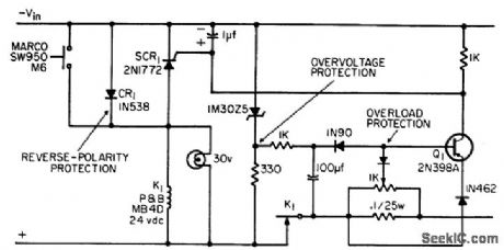
Circuit uses simple relay instead of customary transistor to break load current when over-load or overvoltage occurs.-J. J. Rado, Versatile SCR Protection for Power Supplies, EEE, 13:8, p 56-62. (View)
View full Circuit Diagram | Comments | Reading(812)
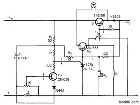
OVERLOAD_PROTECTION_1
Published:2009/7/21 10:17:00 Author:Jessie
Series regulator with degenerative feedback provides both overload and short-circuit protection. Output voltage is automatically restored when over load is removed.-M. A. Torla, Series Regulator Gives Overload Protection, Electronics, 39:15, p 104-105. (View)
View full Circuit Diagram | Comments | Reading(1316)
OVERLOAD_PROTECTION_WITH_RIPPLE_CLIPPING
Published:2009/7/21 10:15:00 Author:Jessie
Power transistor interrupts load when current exceeds safe limit, and also serves as part of ripple dipper.-J. J. Rado, Versatile SCR Protection for Power Supplies, EEE, 13:8, p 56-62. (View)
View full Circuit Diagram | Comments | Reading(813)
REVERSE_PHASE_PROTECTION
Published:2009/7/21 10:14:00 Author:Jessie
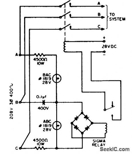
Used to protect navigation system against damage if phase rotation is reversed by careless or accidental power transfers. With correct rotation, lamp ABC lights and relay closes control circuit to allow operation. With reverse phase rotation, lamp BAC lights and relay does not close.-J. J. Pirch, Simple Reverse-Phase Protection, EEE, 11:12, p 26. (View)
View full Circuit Diagram | Comments | Reading(2982)
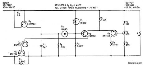
SERIES_REGULATOR_WITH_OVERLOAD_PROTECTION
Published:2009/7/21 10:13:00 Author:Jessie
Tunnel diode and transistor serve as overload sensing circuit used to trigger monostable mvbr, to protect series-pass transistors against overload. Circuit resets continuously after overload until trouble is cleared. Protection is adequate for resistive loads only.-J. Takesuye and H. Weber, Silicon Power Transistors Provide New Solutions to Voltage Control Problems, Motorola Application Note AN-163, Aug. 1965. (View)
View full Circuit Diagram | Comments | Reading(958)
AND_GATE_PROTECTS_FROM_VOLTAGE_FAILURE
Published:2009/7/21 10:11:00 Author:Jessie
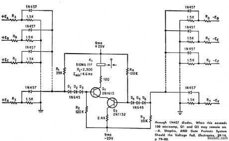
Deteuls absence of any one of several critical supply voltages of either polarity and energizes interlocking relay to prevent damage to components. Number of monitored circuits is limited by sum of leakage currents through 1N457 diodes. When this exceeds 100 microamp, Q1 and Q2 may remain on. –A. Shapiro, AND Gate Protects System Should the Voltage Fail, Electronics, 39:14, p 79-80. (View)
View full Circuit Diagram | Comments | Reading(970)
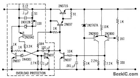
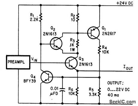
OVERLOAD_PROTECTION
Published:2009/7/21 10:09:00 Author:Jessie
Transistor Q4 in conventional series regulated power supply is protected against charging current of load capacitance C2 by sharp current-limiting-characteristic protection circuit that operates statically, without need for resetting, in preset range of from 50 to 250 ma, and provides instantaneous response when regulator transistor is overloaded. Line regulation is 0.001% and load regulation is 0.002%.-H. D. Ervin, Transistor Power Supply has Overload Protection, Electronics, 31:25, p 74-75. (View)
View full Circuit Diagram | Comments | Reading(0)
MISSING_PULSE_DETECTOR
Published:2009/7/21 10:06:00 Author:Jessie
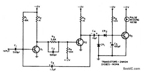
Turns on lamp if one of input pulses in continuous pulse input is missing. Pulses are very narrow (4 microsec wide) and 50 microsec apart for low duty cycle; Q1 and Q2 form pulse stretcher that increases widlh to about 40 microsec. In absence of stretched pulse, Q3 loses its bias and is turned on, making lamp light. -C. Gerston, Missing-Pulse Detector for Narrow Pulses, EEE, 12:8, p 72-74. (View)
View full Circuit Diagram | Comments | Reading(2)
SHORT_CIRCUIT_PROOF_SHUNT_TYPE_SUPPLY_
Published:2009/7/21 10:52:00 Author:Jessie
Output is variable from 1 to 17 V, maximum ripple is 1 mv peak-to-peak, and maximum current is 2.5 amp at 1 V or 0.8 amp at 17 V. After two hours of warmup, output drift is negligible (fraction of mv).-E. Baldinger and W. Czaja, Designing Highly Stable Transistor Power Supplies, Electronics, 32:39, p 70-73. (View)
View full Circuit Diagram | Comments | Reading(594)
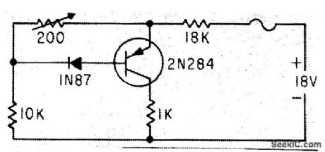
TRANSISTOR_OVERVOLTAGE_FUSE
Published:2009/7/21 10:51:00 Author:Jessie
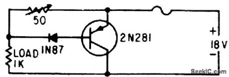
Proteclive circuit uses one resistor, one diode, amd one transistor. Transistor across supply line is cut off by 1N87 diode until overload occurs. When transistor conducts, fuse is open by current that would ordinarily destroy transistors being protected (represented here by 1K load).-K. Redmond, Low-Cost Transistor Overload Safety Circuit, Electronics, 33:42, p 102. (View)
View full Circuit Diagram | Comments | Reading(729)
ELECTRONIC_FUSE
Published:2009/7/21 10:50:00 Author:Jessie
Switches high series resistance R3 into circuit only when overload or short-circuit occurs. R3 is shunted out of load R2 by Q2,-L. Payerl, Overload Protection for D-C Amplifier, Electronics, 39:7, p 91. (View)
View full Circuit Diagram | Comments | Reading(7)
ZENER_GATED_SCR_PROTECTS_POWER_TRANSISTORS
Published:2009/7/21 10:49:00 Author:Jessie
Scr serves as controllable short-circuit across power transistors. Reaction time is about 2 microsec.-C. A. Blanchard, Zener-Gated SCR Protection for Power Transistors, EEE, 14:5, p 117-118. (View)
View full Circuit Diagram | Comments | Reading(861)
SHORT_CIRCUIT_DETECTOR
Published:2009/7/21 10:48:00 Author:Jessie
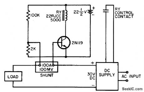
Shunt used in d-c power circuit for metering also serves here to drive base of transistor that senses over-loads. Relay in transistor circuit disconnects d-c power when drop ccross 100-mv shunt approaches 400 mv (4 times normal load current).-J. J. Pirch, Single-Transistor Short-Circuit Detector, EEE, 12:16, p 64. (View)
View full Circuit Diagram | Comments | Reading(1231)
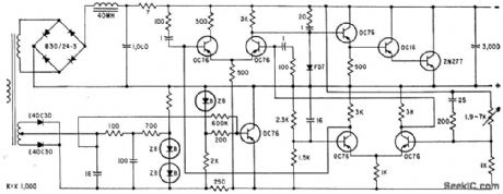
400_CPS_SCR_REGULATED_SUPPLY
Published:2009/7/21 10:47:00 Author:Jessie
Converts 115 V at 400 cps to 24 V d-c, using ramp-and-pedestal control of ser firing. Regulation is excellent, ripple can be as small as desired, and sync circuit provides automatic short-circuit protection. Efficiency is 95% because power dissipation is low when scr's are not conducting. Either side of supply can be grounded.-G. B. Jordan,A Novel Sync Circuit for Scr Control, EEE, 14:7, p 58-61. (View)
View full Circuit Diagram | Comments | Reading(844)
LOW_DISSIPATION_TRANSISTOR_OVERVOLT_AGE_FUSE
Published:2009/7/21 10:45:00 Author:Jessie
Series collector resistor lowers dissipation of fuse circuit during normal line voltages, and serves also as voltage regulator for transistors being protected (represented by 1K load).-K. Redmond, Low-Cost Transistor Overload Safety Circuit, Electronics, 33:42, p 102. (View)
View full Circuit Diagram | Comments | Reading(644)
BATTERY_STANDBY
Published:2009/7/21 10:44:00 Author:Jessie
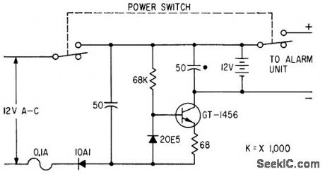
Protects against false alarms caused by power failure of intruder detector.-S. M. Bogno, Sensitive Capacitance Intruder Alarm, Electronics, 33:38, p 65-67. (View)
View full Circuit Diagram | Comments | Reading(690)
OVERLOAD_PROTECTION_2
Published:2009/7/21 10:42:00 Author:Jessie
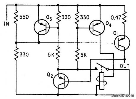
Switches power off rapidly to prevent current overloads from damaging transistors in breadboard circuits under test. Voltage drop across 0.47-ohm resistor and Q1 biases Q2 to saturation, causing Q3 and Q4 to open power relay.- F. W. Kear, Laboratory Supply for Transistors, Electronics, 35:30, p 55-57. (View)
View full Circuit Diagram | Comments | Reading(678)
PULSED_TRANSDUCER_METER_PROTECTION
Published:2009/7/21 10:41:00 Author:Jessie
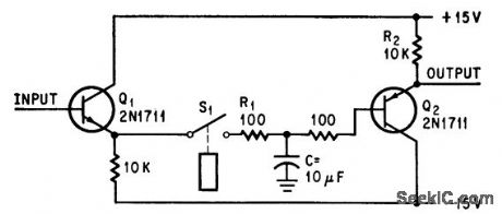
Circuit stores transducer output while transducer is momentarily disconnected during pulse period by relay drive circuit that operates coincidentally with transducer pulse drive. Metet voltage is stored by C during pulse period. No storage occurs when S1 is closed; meter then indicates voltage proportional to transducer current, as gain of circuit is 1. -C. Pittman and B. Birnbaum, Circuit Protects Meter from Periodic Current Spikes, Electronics, 39:12, p 108. (View)
View full Circuit Diagram | Comments | Reading(710)
MINIMUM_DISSIPATION_SERIES_REGULATOR
Published:2009/7/21 10:40:00 Author:Jessie
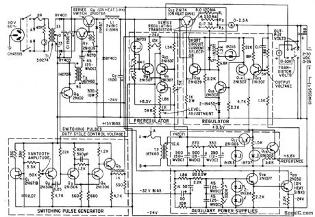
Regulation of short-circuit-proof variable voltage-regulated supply is 0.1 % for 2 to 30 V output and up to 2 amp. Dissipation in series regulating transistor is minimized by controlling on time of series switching transistor Q8. -J. S. Riordon, Power Supply Uses Switching Preregulation, Electronics, 35:10, p 62-64. (View)
View full Circuit Diagram | Comments | Reading(768)
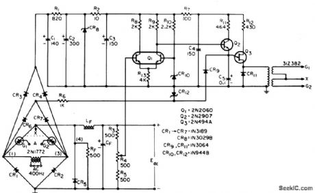
FAIL_SAFE_TWT_FILAMENT_REGULATOR
Published:2009/7/21 10:33:00 Author:Jessie
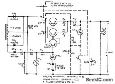
Designed to supply well-regulated voltage of 6.3 V d-c at 2 amp to filament of travelling-wave tube, while providing temperature compensation and fail-safe capability. Protective circuit shown in heavy dotted lines operates if one of transistors shorts or if filament voltage rises for any other reason. -G. Stanley, Fail Safe DC Filament Regulator, EEE, 10-6, 32-33. (View)
View full Circuit Diagram | Comments | Reading(1379)
| Pages:128/312 At 20121122123124125126127128129130131132133134135136137138139140Under 20 |
Circuit Categories
power supply circuit
Amplifier Circuit
Basic Circuit
LED and Light Circuit
Sensor Circuit
Signal Processing
Electrical Equipment Circuit
Control Circuit
Remote Control Circuit
A/D-D/A Converter Circuit
Audio Circuit
Measuring and Test Circuit
Communication Circuit
Computer-Related Circuit
555 Circuit
Automotive Circuit
Repairing Circuit