
Index 199
35_W_FOR_CW
Published:2009/7/11 2:24:00 Author:May
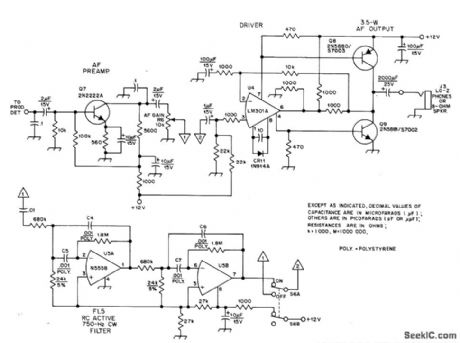
Discrete devices minimize distortion and eliminate fuzziness while listening to low-level CW signals in communication receiver covering 1.8-2 MHz. RC active bandpass filter peaked at 800 Hz improves S/N ratio for weak signals. Adiust BFO of receiver to 800 Hz.Two-part article gives all other circuits of recelver,-D.DeMaw,His Eminence-the Receivel,OST, Part 2-July 1976,p 14-17(Part 1-June 1976,p 27-30), (View)
View full Circuit Diagram | Comments | Reading(901)
KEYER
Published:2009/7/11 2:20:00 Author:May
Uses gating and flip-flop functions to generate dots and dashes under control of gated clock. SN7413 Schmitt trigger is connected as relaxation oscillator. Circuit provides minimum spacing between dots and dashes re gardless of paddle movements.-A. D. Helf rick, A Simple IC Keyer, 73 Magazine, Dec. 1973, p 37-38. (View)
View full Circuit Diagram | Comments | Reading(6009)
ANALOG_VOLTAGE_CAMERA_IMAGE_TRACKER
Published:2009/7/11 2:20:00 Author:May
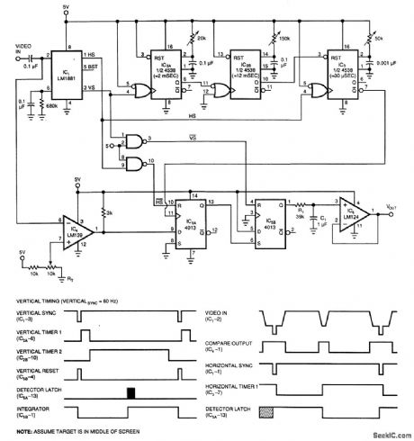
By using a low-cost RS-170 camera and this circuit, a voltage that trades the position of an object in the field of view of a camera is generated. IC2A and IC2B form a valid video gate that holds IC3 in reset during the internal vertical blanking to prevent false interpretation of the UB1 as black video. IC4 is a black level detector. The circuit tests for a black object in the middle of each video line. IC5 latches the comparator's output and produces a square wave whose duty cycle depends on where the black level is detected in the video field. R1. C1. and IC6 integrate and buffer the analog output voltage. (View)
View full Circuit Diagram | Comments | Reading(1159)
KEYEB_WITH_4VlEMORY
Published:2009/7/11 2:17:00 Author:May
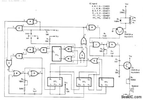
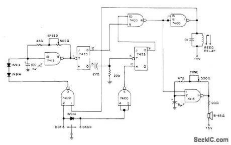
Includes sidetone oscillator and dash-dot memory along with variable speed, automatic spacing, and self-completing dots and dashes. If dot paddleis pressed and released while keyer is generating dash, dot is generated with correct spacing after dash is completed. Gates A, B, and C form gated MVBR.Gates D, E, O, and P serve to complete characters. JK flip-flops FF1 and FF2, D flip-flop FF3, and gates F, G, and L provide character-shaping required for dash-dot memory using gates M, N, and RS flip-flop FF4. Gates J and K generate audio sidetone. K1 is B & F Enterprises ERA21061 SPST reed relay. Supply can be 9-V battery.-T. R. Crawford, A Low-Power Cosmos Electronic Keyer in Two Versions, CQ, Nov.1975, p 17-24. (View)
View full Circuit Diagram | Comments | Reading(742)
CQ_ON_TAPE
Published:2009/7/11 2:12:00 Author:May

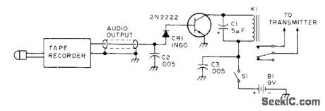
Frequently used code message such as amateur radio CQ call is recorded by keying audio oscillator with desired message and picking up oscillator output with microphone of endless-loop cassette or other tape recorder. Rewound recording is played back through single-transistor stage connected as shown for driving keying relay of transmitter.Circuit requires shielding.-Circuits, 73 Magazine, July 1977, p 34. (View)
View full Circuit Diagram | Comments | Reading(721)
MORSE_CODE_SET
Published:2009/7/11 2:12:00 Author:May
National LM3909 flasher IC is connected as tone oscillator that simultaneously drives loudspeakers at both sending and receiving ends of wire line used for Morsecode communication system. Single alkaline penlight cell lasts 3 months to 1 yeardepending on usage. Three-wire system using parallel telegraph keys eliminates need for send.receive switch. Tone frequency is about 400 Hz.- Linear Applications, Vol. 2, National Semiconductor, Santa Clara, CA, 1976, AN-154, p 5-6. (View)
View full Circuit Diagram | Comments | Reading(1575)
ULTRASONIC_PEST_REPELLER_II
Published:2009/7/11 2:09:00 Author:May
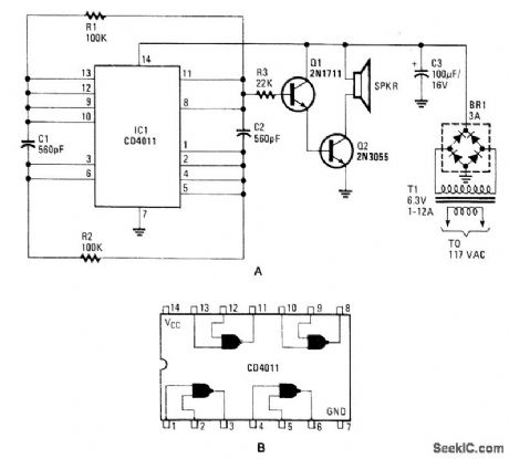
A CD4011 Quad NAND gate acts as an oscillator, operating around 40 kHz. The small amount of filtering used modulates this with 120-Hz hum. The speaker is a small tweeter for hi-fi applications. (View)
View full Circuit Diagram | Comments | Reading(1483)
HIGH_ACCURACY_CURVE_TRACER
Published:2009/7/11 2:09:00 Author:May
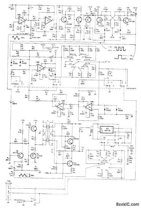
Can be used with any calibrated CRO, formatching and testing transistors or diodes by comparing performance curves. All opamps are 709C. Triangle wave generated by IC1-IC2 is fed to Schmitt trigget Q1-Q2, which generates square wave having transitions at zero voltagecrossings of input triangle. Q3 clamps square wave to 6.3 V P-P. Flipflop Q4-Q5 generates same square wave but at half the frequency of triangle wave. Combining square waves gives three-step staircase voltage having steps precisely in phase with zero signal crossings of triangle wave. T1 is UTC A-20 audio transformer, and T2 is Stancor P-6411 I5-W 1:1 isolation transformer. Article covers construction, alignment, and use, and gives circuit of suitable regulated supply operating from ±110 and ±6.3 V available in AN/USM-140C military version of Hewlett-Packard 170 CRO.-A. J. Klappenberger, An Accurate Solid State Component Curve Tracer, CQ, July 1974, p 20-24 and 82. (View)
View full Circuit Diagram | Comments | Reading(1103)
40_METER_DIRECT_CONVERSION
Published:2009/7/11 2:07:00 Author:May
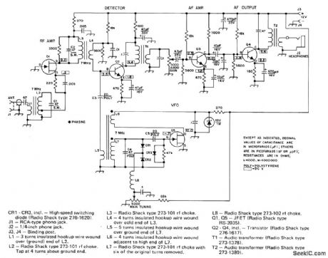
Simple, foolproof circuit design uses discrete components mounted on printed-circuit board shaped to fit in oval herring can. Single 7-MHz RF stage and voltage-tuned VFO feed produgt detector Q2 that drives 2-stage AF amplifier having peak response at about 650 Hz for most comfortable CW listening. VFO uses Armstrong or tickler-feedback circuit, with CR1 and CR2 connected as voltage-variable-capacitance diodes. Zener regulator powers VFO circuit for good frequency stability Receiver will tune any 100-kHz segment of 40-meter band.-J Rusgrove,The Herring-Aid Five,QST,July 1976,p 20-23. (View)
View full Circuit Diagram | Comments | Reading(1248)
ULTRASONIC_PEST_REPELLER_I
Published:2009/7/11 2:06:00 Author:May
An NE555 timer is used to generate an ultrasonic signal in the 20- to 65-kHz range. The speaker is a small piezoelectric tweeter with response above 20 kHz. These frequencies are said to be annoying to rats. mice. and insects. (View)
View full Circuit Diagram | Comments | Reading(1859)
SIMPLE_WWV_CHECK
Published:2009/7/11 2:04:00 Author:May
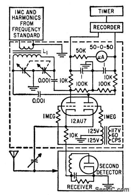
Permits making accurate check of local frequency standard quickly and easily by direct comparison with WWV signctls. Uses one receiver. Two signals, at0 and 180°, are obtained from local standard clock. Switch 12AU7 alternately connects one triode detector output and 0°signal simulta-neously to antenna, and then other triode detoctor output simultaneously with 180°signal.Doppler error is minimized by averaging hourly 3-minute readings over 8-hour period.Accuracy is one part in 100,000,000.-J. F.Brumbach, Fast WWV Check of Frequency Standard, Electronics, 32:13, p76-79. (View)
View full Circuit Diagram | Comments | Reading(670)
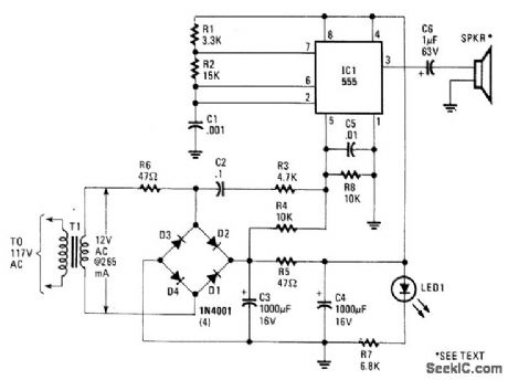
ULTRASONIC_SOUND_SOURCE
Published:2009/7/11 2:04:00 Author:May
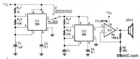
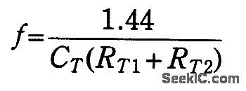
Using two NE555 timer IC devices, this circuit generates either pulsed or continuous ultrasonic signals. The sound frequency is:The values of CT for both pulse rate and ultrasonic frequencies can be calculated this way. SPKR is a small hi-ft tweeter. (View)
View full Circuit Diagram | Comments | Reading(726)
TRANSISTOR_STABILIZED_CMOS_FOUR_GATE_CLOCK
Published:2009/7/11 2:01:00 Author:May
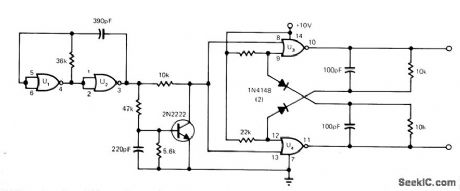
Addition of 2N2222 transistor to clock using 4001 CMOS quad two-input NOR-gate IC boosts temperature stability to 0.05%/℃ and supply stability to 0.05%/V, Transistor circuit differentiates output signal of oscillator U1-U2 and provides pulses for toggling flipdlop U3-U4.-M. Eaton, Symmetrical.CMOS clock is inexpensive, EDN Magazine, March 20, 1974, p 80 and 83. (View)
View full Circuit Diagram | Comments | Reading(1190)
FOUR_PHASE_CLOCK
Published:2009/7/11 2:00:00 Author:May
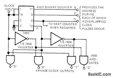
Provides expandable 3-bit binary output and four overlapping clock pulses for each unique binary output. A-output of 7493 binary counter is used along with dock input to form four-phase overlapping clock function. Article indudes timing diagram that shows sequence of output pulses. Developed for use in addlessing multiplexers, ROMs, and other digital units,-B. Brandstedt, Clock Pulse Generator Has Addressable Output, EDN Magazine. Dec. 15, 1972, p 42. (View)
View full Circuit Diagram | Comments | Reading(1802)
TWO_IC_MEDIUM_WAVE_RECEIVER
Published:2009/7/17 3:12:00 Author:Jessie
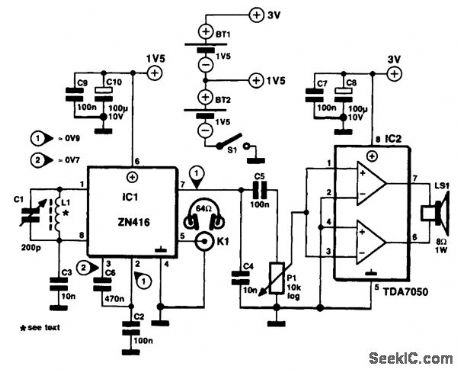
The antenna is an inductor, L1, consisting of about 60 turns of 0.2-mm (SWG36) enameled copper wire on a ferrite rod with a diameter of 12 mm and a length of about 12 cm. The inductor is tuned with a 500-pF foil-dielectric variable capacitor, C1. The audio power amplifier, a TDA7050, is required only if you want to use a small loudspeaker instead of, or in addition to, the headphones. The AF power amplifier also adds the luxury of a volume control to the receiver. The receiver IC operates at 1.54 V from only one of two series-connected AA (penlight) batteries, which supply 3 V to the TDA7050. Current consumption is of the order of 8 mA. (View)
View full Circuit Diagram | Comments | Reading(1218)
VTR_CLOCK
Published:2009/7/11 1:58:00 Author:May
Locked oscillator using only two-input NAND gate and 555 timer provides logic clock signal for videotape recorder. Vertical sync signal, stripped from video information re corded on tape, is used as control signal. C1 controls locking range forfree running trequency of 555. When C2 is charging (555 output is high), R2 and D1 determine time constant T1. During discharge of C2, D1 is reverse-biased and discharge time constant T2 is determined by R3 and R4. -L. Saunders, Locked Oscillator Uses a 555 Timer, EDN Magazine, June 20, 1975, p 114. (View)
View full Circuit Diagram | Comments | Reading(713)
CESIUM_CLOCK_SYNTHESIZER
Published:2009/7/11 1:53:00 Author:May
Crystol 5-Mc oscillator is monitored by natural resonance frequency of cesium (9,192.63184 Mc) to get primary frequency standard. Output signals are 100 kc and 1, 5, 10, and 100 Mc, with accuracy of one port in one billion. Starting with 5 Mc, 9,180 Mc is achieved as harmonic by direct multiplication. Remaining 12.631840 Mc is obtained from 5-Mc source by frequency muhiplication, division, and mixing. Circuit shows input section of synthesizer used for this purpose.-W.A. Mainberger, Primary Frequency Standard Using Resonant Cesium, Electronics, 31:45, p80-85. (View)
View full Circuit Diagram | Comments | Reading(714)
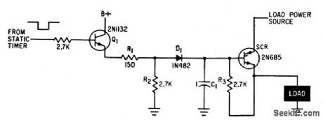
CLOCK_OUTPUT_DRIVER
Published:2009/7/11 1:50:00 Author:May
Driver transistor Q1 is pulsed on at preset time, to supply drive current lo gate of scr so it applies current to load. When scr fires, D1 is back-biased, removing rectifer gate from driver output.-R.S. Reed, Rugged Arming-Fuzing Timer for Atomic Artillery Missile, Electronics,34:38, p48-51. (View)
View full Circuit Diagram | Comments | Reading(616)
10_Hz_CLOCK
Published:2009/7/11 1:50:00 Author:May
Stable and accurate clock is generated by high-precision 100-kHz crystal oscillator and decade divider ehain. Used in 20-meter receiver as part of digital display systemthat shows frequency of received signal aftercounting HFO,LO,and BFO outputs,summing counts, and displaying result.-M. A. Chapman, High Performance 20-Meter Receiver with Digital Frequency Readout, Ham Fladio, Nov 1977, p 56-65. (View)
View full Circuit Diagram | Comments | Reading(1671)
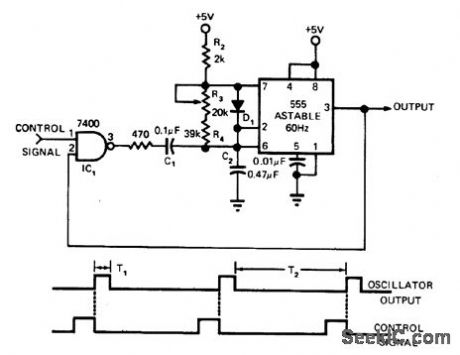
SYNCHRONIZER
Published:2009/7/11 1:48:00 Author:May
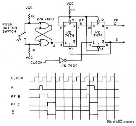
For each switch closure, circuit produces one output pulse that is one clock period wide, synchronized with clock. When switch is closed, debouncing latch using 7400 gates goes high and makes flip-flop B high. Next clock pulse makes flip-flop C high and resets flip-flop B. At next clock pulse, flip-flop C goes low to complete cycle of operation.-E. E. Hriv-nak, House Cleaning the Logical Way, 73 Mag-azine, Aug. 1974, p 85-90. (View)
View full Circuit Diagram | Comments | Reading(2676)
| Pages:199/471 At 20181182183184185186187188189190191192193194195196197198199200Under 20 |
Circuit Categories
power supply circuit
Amplifier Circuit
Basic Circuit
LED and Light Circuit
Sensor Circuit
Signal Processing
Electrical Equipment Circuit
Control Circuit
Remote Control Circuit
A/D-D/A Converter Circuit
Audio Circuit
Measuring and Test Circuit
Communication Circuit
Computer-Related Circuit
555 Circuit
Automotive Circuit
Repairing Circuit