
Index 201
800_Hz_CLOCK_FOR_CASSETTE_RECORDER
Published:2009/7/10 23:54:00 Author:May
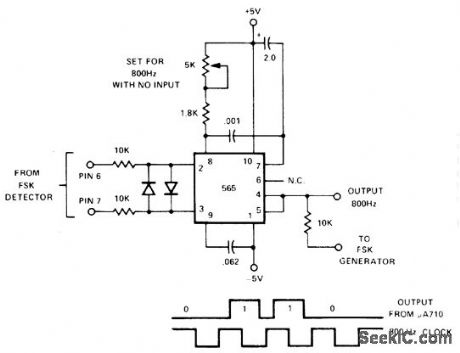
565 PLLis set for free-running at 800 Hz with no input. When data pulses extracted from FSK recorded data on cassette tape are fed in,clock is synchronized to data and stays in sync for up to seven 0s in succession.- Signetics AnalogData Manual, Signetics,Sunnyvale,CA,1977,p 859-860. (View)
View full Circuit Diagram | Comments | Reading(1313)
CRYSTAL_CHECKER
Published:2009/7/10 23:53:00 Author:May
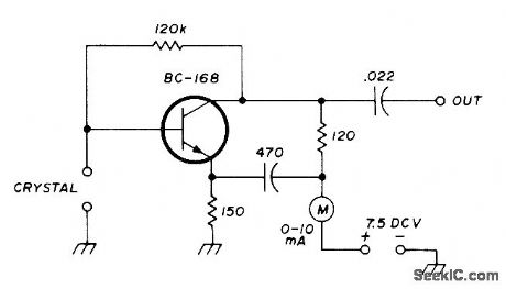
Simple oscillator circuit checks crystal activity and resonant frequency, as required when choosing matched crystals for filters, For frequency check, signal from oscillator is injected into frequency counter. Values shown are for crystals around 5.5 MHz. For matching purposes, higheraccu racy is obtained by reading harmonics of oscillator.-J. Perolo, Practical Considerations in Crystal-Filter Design, Ham Radio, Nov. 1976, p 34-38. (View)
View full Circuit Diagram | Comments | Reading(3389)
DIODE_CURVE_TRACER
Published:2009/7/10 23:51:00 Author:May
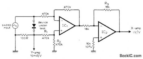
Circuit is designed to produce voltage-current characteristic curve of diode or other two-terminal device on oscilloscope. Sweep input can be any low-voltage AC source, such as 20-V Variac. Three-terminal devices may be traced if suitable external bias is provided. Opamps are 741.-S. Cahill, Diode Curve Tracer for Oscilloscope, Wireless World, Feb. 1976, p 76. (View)
View full Circuit Diagram | Comments | Reading(1169)
CHECKING_DIODES_WITH_CRO
Published:2009/7/10 23:50:00 Author:May
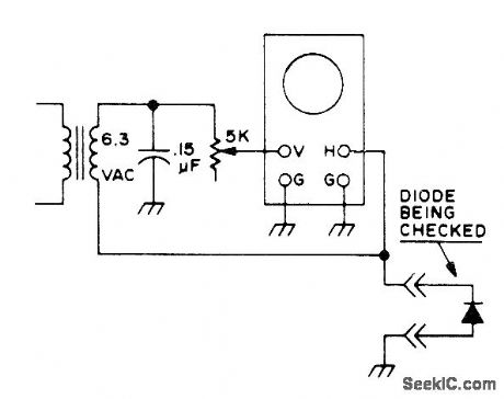
Simple oscilloscope setup checks and matches diodes. Sort diodes according to type, set potto givedesired trace size for good diode, then note relative sizes of traces obtained for unknown diodes. Reject diodes showing fuzz or ripple on oscilloscope trace.-Novice Q & A, 73 Magazine, March 1977, p 187. (View)
View full Circuit Diagram | Comments | Reading(598)
CRYSTAL_CONTROLLED_TIMER
Published:2009/7/10 23:48:00 Author:May
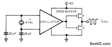
Intersil 7209 clystal oscillator provides buffered CMOS output capable of driving over five TTL loads any crystal frequency up to 10 MHz.Used in applications requiring high-accuracy buffered timingsignals for system clocks.-B.O.'Neil,IC Timers-the Old Reliable 555 Has Company,EDN Magazine, Sept.5,1977,p 89-93. (View)
View full Circuit Diagram | Comments | Reading(722)
MOS_FOUR_GATE_CLOCK
Published:2009/7/10 23:47:00 Author:May
Only one 4001 CMOS quad two-input NOR-gate 10 is needed for symmetrical complementary-output clock having good temperature and supply stability.Gates U1 and U2 form astable oscillator producing positive-going pulses used to triggir divide-by-2 flip-flop U3-U4. Circuit will operate over wide range of supply voltages and temperatures,-M,Eaton,Symmetrical CMOS clock is Inexpensive,EDN Magazine.March 20,1974,p 80 and 83. (View)
View full Circuit Diagram | Comments | Reading(650)
RC_CLOCK
Published:2009/7/10 23:46:00 Author:May
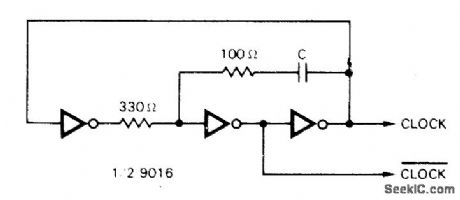
Simple TTL clock generator is suitable for most TTL systems. Requires only half of hex inverter package and three passive com ponents. Clock frequency depends on value of C: 200 pF gives 5 MHz; 1600 pF gives 1 MHz; 0.018 μF gives 100 kHz; and 0 18 μF gives 10 kHz.-Circuits, 73 Magazine, Aug. 1974, p 99. (View)
View full Circuit Diagram | Comments | Reading(2846)
GATE_TURNOFF_D_C_CHOPPER
Published:2009/7/10 23:41:00 Author:May
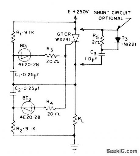
Will chop 1 kw at 1 kc. Ralio of on time to off time can be adjusted to control power, voltage, tem-perature, and other parameters. Shunt circuit allows larger currents to be chopped.-J. W.Motto, Jr, Switching Circuits Using the Gote Turnoff Controlled Rectifier, EEE, 11:3, p52-55. (View)
View full Circuit Diagram | Comments | Reading(596)
JFET_CURVE_TRACER
Published:2009/7/10 23:37:00 Author:May
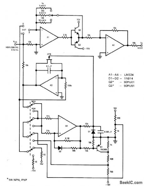
Quad opamp and J176 JFET switch form basis of simple curve tracer that can be used with any CR0. Circuit displays drain current versus gate voltage for both Pchannel and N-channel JFETs at constant drain voltage. Sweep time is 10 ms. Sweep rate is 0.5 V/mswith maximum gate voltage of ±5V. Drain current is fed to vertical input and gate voltage to horizontal input.- FET Databook, National Semiconductor, Santa Clara, CA, 1977, p 6-506-51. (View)
View full Circuit Diagram | Comments | Reading(1128)
AF_SIGNAL_INJECTOR
Published:2009/7/10 23:36:00 Author:May
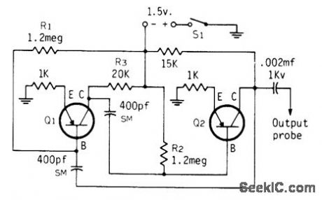
Can be built into penlight housing, using single penlight cell or 1.5-V mercury cell for power. Output probe for feeding signal to audio circuit under test is about linch length of stiff wire, pointed. For more output, run ground lead to equipment under test.Q1 can be HEP253, 2N519, 2N741A, 2N2929, or equivalent. Q2 can be HEP3, 2N1280, 2N2273, SK3005, or equivalent. Adjust R, and R, for good output, and ad just R3 as required for good tone.To use, touch probe to input of any receiver or high-fidelity audio circuit. Tone should be heard from loudspeaker if circuit is good between probe and loudspeaken-C.J. Schauers, Transistorized Signal Tracer, CQ4 Sept. 1973, p 12 and14. (View)
View full Circuit Diagram | Comments | Reading(1046)
WATCH_CRYSTAL_TIMER
Published:2009/7/10 23:30:00 Author:May
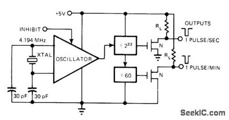
When used withstandard 4.194-MHz watch crystal, Intersil 7213 crystal-controlled timer generates outputs of 1 pulse per second and 1 pulse per minute,using internal divider chain CMOS dynamic and static dividers keep power dissipation under 1 mW with 5-V supply,-B.O'Neil,IC Timers-the Old Reliable 555 Has Company,EDN Magazine, Sept 5,1977,p 89-93, (View)
View full Circuit Diagram | Comments | Reading(901)
CLOCK_FOR_MC6800
Published:2009/7/10 23:29:00 Author:May

Produces nonoverlapping complementary 5-V clock outputs as required for phase 1 and phase 2 clock inputs of microprocessor. Oscillator can be any source having maximum frequency of 1 MHz with TTL Ievels and 50% duty cycle, such as Motorola K1100A. MC3000 and MC3001 TTL gates are chosen for their speed and drive characterlstics.All transistors are MPQ6842.- Microprocessor Applications Manual (Motorola Series in Solid-State Electronics), McGraw-Hill, New York, NY 1975, p 4-1-4-6. (View)
View full Circuit Diagram | Comments | Reading(1474)
GATE_TURNOFF_CHOPS_28V_AT_1OO_KC
Published:2009/7/10 23:29:00 Author:May
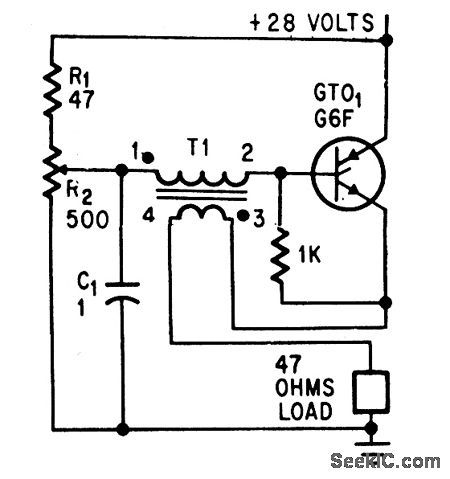
Saturctble transformer and gate turnoff scr give simple 100-kc chopper in which potentiometer R2 controls on-to-off timer.-D.R. Grafham, Now the Gate Turnoff Switch Speeds Up D-C Switching, Electronics, 37:12, p64-71. (View)
View full Circuit Diagram | Comments | Reading(526)
1_Hz_CLOCK_WITH_BATTERY_BACKUP
Published:2009/7/10 23:28:00 Author:May

Circuit normally produces output pulses at 1-s intervals with basic accuracy corresponding to that of power-line frequency. Programmable 8260 timer operates as divide-by-60 counter produc ing output swing compatible with TTL or 5-V CMOS loads. With backup power applied to OR gate D1-D2, circuit operates reliably at 1 s over supply range of 5-15 V. Power drain is minimized at ±5 V.-W. G. Jung, IC Timer Cookbook, Howard W. Sams, Indianapolis, IN, 1977, p 214-215. (View)
View full Circuit Diagram | Comments | Reading(1260)
TELEPHONE_MESSAGE_TAKER
Published:2009/7/10 23:27:00 Author:May
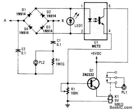
This circuit operates on the ringing voltage of the telephone to trigger a tape recorder to record messages. K1 can be made to latch using extra contacts if the tape recorder requires a constant-contact closure. (View)
View full Circuit Diagram | Comments | Reading(973)
NORMALLY_ON_GTO_CHOPPER
Published:2009/7/10 23:25:00 Author:May
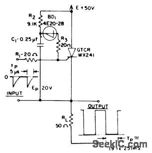
Small trigger at input removes applied voltage from load for duralion of time constant R2-C1. Handles 1kw at 1 kc.-J. W. Motto, Jr, Swilching Circuits Using the Gate Turnoff Controlled Rectifier, EEE, 11:3, p.52-55. (View)
View full Circuit Diagram | Comments | Reading(523)
320_kHz_FOR_CALCULATOR
Published:2009/7/10 23:22:00 Author:May
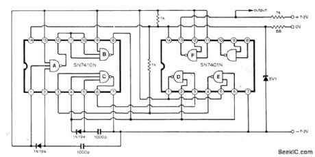

Two low-cost TTL ICs generate 320-kHz clock signals for electronic desk calculator, Output swings between +7.2 V and -7.2 V. NAND gates of ICs are connected to form free-running multivibrator, with self-starting gate C ensuring that clock waveform is availableas soon as supply voltage is applied.-T. J. Terrell, Clock Generator for Electronic Calculators, Wireless World, Dee. 1975, p 575. (View)
View full Circuit Diagram | Comments | Reading(1652)
ADJUSTABLE_CLOCK_WITH_MEMORY_READY
Published:2009/7/10 23:20:00 Author:May
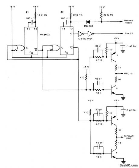
Additional timing resistor is switched in or out of MC8602 pulse-width generator for phade-2 clock to provide memory-ready feature along with variable clock frequency for MC6800 microprocessor.Selection of timing resistors for phade 1 and phase 2permits generation of all combination of phase 1,phase 2,and stretched phase 2 pulse widths. All transistors are MPQ6842. - Microprocess Applications Manual (Motorola Series in Soil-State Electronics), McGraw-Hill,NEW York,NY,1978,P 4-61. (View)
View full Circuit Diagram | Comments | Reading(829)
OPTOELECTRONIC_CHOPPER_WITH_NEONS
Published:2009/7/10 23:20:00 Author:May
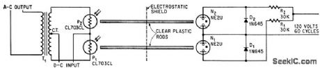
Used with amplifier of sensitive potentiometer recorder.Diodes D1 and D2 short-circuit lamps on alternate half-cycles. Photoelectric chopping eliminates stray interference from a-c line and minimizes heat dissipation problems.-W.Moore,Photoconductors Chop D-C Signal levels,Electronics,38:9,p61-62 (View)
View full Circuit Diagram | Comments | Reading(607)
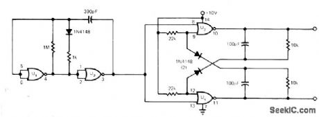
CALL_TONE_GENERATOR
Published:2009/7/10 23:19:00 Author:May
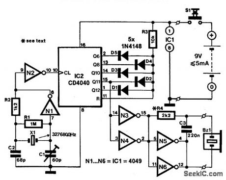
Amateur VHF relay stations are normally actuated by a 1750-Hz call tone. This might give problems if the relevant sending equipment has no internal call-tone generator, if it does not have sufficiently accurate frequencies, or if the tone duration is not long enough to securely energize the relevant relay.These problems can be overcome by the stand-alone generator described here. Simply placed in front of the microphone, it makes absolutely certain that the relay station is actuated. The generator consists of a quartz oscillator, a frequency counter and a buffer-amplifier-all contained in just two CMOS ICs. It is powered by a 9-V (p-p) battery, from which it draws a current of around 5 mA.Gates N1 and N2 form an oscillator that is controlled by a 3.27680-MHz crystal and provides clock pulses to IC2, which is connected as a programmable scaler. Diodes D1 through D5 determine the divide factor of 1872. Counter output Q1 provides the wanted 1 750-Hz signal, which is buffered by N3 through N6 before being applied to a piezoelectric buzzer. Capacitor C3 suppresses any harmonics, while R4 determines the volume of the output signal. (View)
View full Circuit Diagram | Comments | Reading(1109)
| Pages:201/471 At 20201202203204205206207208209210211212213214215216217218219220Under 20 |
Circuit Categories
power supply circuit
Amplifier Circuit
Basic Circuit
LED and Light Circuit
Sensor Circuit
Signal Processing
Electrical Equipment Circuit
Control Circuit
Remote Control Circuit
A/D-D/A Converter Circuit
Audio Circuit
Measuring and Test Circuit
Communication Circuit
Computer-Related Circuit
555 Circuit
Automotive Circuit
Repairing Circuit