
Index 205
METRONOME_II
Published:2009/7/10 21:21:00 Author:May
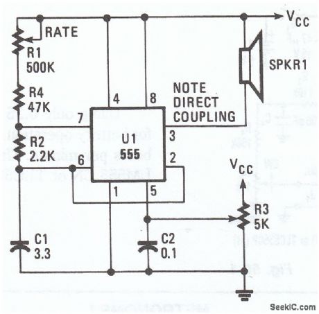
This electronomic metronome, using a 555 oscillator/timer, provides 10 to 40 beats per minute. The frequency is controlled by R3. (View)
View full Circuit Diagram | Comments | Reading(615)
ABSOLUTE_TE_MPERATURE_SENSING
Published:2009/7/10 21:20:00 Author:May
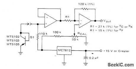
Silicon temperature sensor (MTS102, MTS103, or MTS105) provides precise temperature-sensing accuracy over range of -40℃to +150℃. Sensor is essentially a transistor with base and collector leads connected together externally; baseemitter voltage drop then decreases linearly with temperature over operating range. Voltage change is amplified by two opamps in series, operating from regulated output of MC7812 regulator. Opamp types are not critical, With Q1 at known temperature, adjust 50K pot to give output voltage equal to TEMP x10 mV. Output voltage is then10 mV per degree in desired temperature scale.- Silicon Temperature Sensors, Motorola, Phoenix, AZ, 1978, DS 2536. (View)
View full Circuit Diagram | Comments | Reading(1376)
SIMPLE_ELECTRONIC_METRONOME
Published:2009/7/10 21:20:00 Author:May
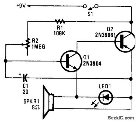
Two complementary transistors form a simple oscillator whose frequency range is from about 0.5 to several Hz. This circuit is useful as a metro-nome, timer, or pacer for exercise equipment. (View)
View full Circuit Diagram | Comments | Reading(711)
0_10O℃_WITH_1°ACCURACY
Published:2009/7/10 21:18:00 Author:May
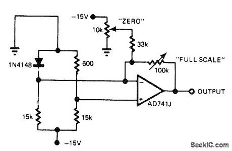
Low-cost diode serves as temperature sensor. To calibrate, place diode in 0℃environment and adjust zero pot for 0-V output, then place diode in 100℃ environment and adjust full-scale pot for 10-V output. Repeat procedure until interaction between adjustments ceases.-J. Williams, Designer's Guide to: Temperature Measurement, EDN Magazine, May 20, 1977, p 71-77. (View)
View full Circuit Diagram | Comments | Reading(1139)
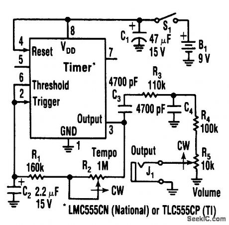
METRONOME_I
Published:2009/7/10 21:18:00 Author:May
This simple metronome circuit offers a range of speeds from largo to prestissimo!The parts values are set so that the repetition rate adjusted by R1 runs from nearly 45 to 184 per minute. (View)
View full Circuit Diagram | Comments | Reading(0)
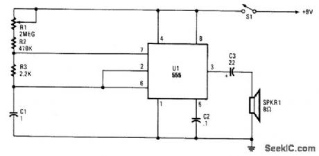
LOW_POWER_METRONOME
Published:2009/7/10 21:16:00 Author:May
Using only 0.25 mA,this metronome is idealfor battery operation.The tempo range is 34 to 246beats per mtnute.Use a CMOS timer, such as an LM555 CN Or TLC55CP. (View)
View full Circuit Diagram | Comments | Reading(1334)
MECHANICALLY_CONTROLLED_BISTABLE
Published:2009/7/10 21:12:00 Author:May
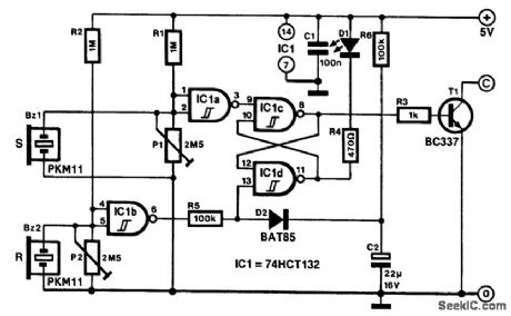
Applications for this mechanically set and reset bistable are found, among others, in antitheft devices and model railway crossings.The transducers are formed by buzzer BZ1, which sets the bistable, and BZ2, which resets it. Their sensitivity is set with P1 and P2, respectively. The presets are adjusted correctly if the output of buffers IC1A and IC1B just toggles from high to low or vice versa.If all have been set correctly, a slight tap of BZ1 will set the bistable. This tap causes T1 to switch on, which enables, for instance, a relay to be energized. At the same time, D1 lights. A tap on BZ2 or on its mounting resets the bistable, whereupon D1 goes out and T1 is switched off. (View)
View full Circuit Diagram | Comments | Reading(628)
BRIDGE_FOR_25_pF_TO_10_μF
Published:2009/7/10 21:11:00 Author:May
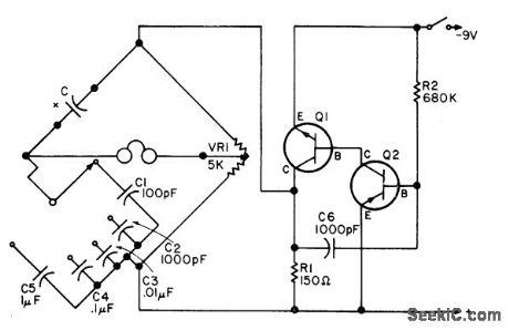
Uses five reference capacitors, one for each range. Linear pot VR1 serves for balancing. High-resistance headphones indicatenull, and capacitor value is then read from setting of VR1. Scale of VR1 is marked for 100 to 10,000 pF for C2 range and 0.01 to 1 μF for C4 range. Scale values are multiplied or divided for other ranges. Calibration is carried out on C2 range, using known capacitor values.Tone oscillator can use almost any pair of transistors, one NPN and the other PNP,-F. G.Rayer, Adrift over Your C's?, 73 Magazine, March 1976, p 106-107. (View)
View full Circuit Diagram | Comments | Reading(919)
INEXPENSIVE_VHF_UHF_DIODE_PF_SWITCH
Published:2009/7/10 21:06:00 Author:May
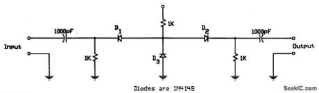
This circuit uses low-cost IN4148 diodes and exhibits about 1.5 dB insertion loss from 10 to 1000 MHz with a few volts of negative bias. D3 conducts and D1/D2 are cut off, which results in 30 to 50 dB isolation. When a few volts of positive bias are applied, D1 and D2 are biased on and D3 is cut off. This circuit should be useful in applications where a low-cost RF switch is necessary. (View)
View full Circuit Diagram | Comments | Reading(693)
R_AND_C_ADAPTEB_FOR_DVM
Published:2009/7/10 21:05:00 Author:May
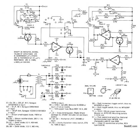
Self-contained circuit provides four ranges of capacitance (0-1, 10, 100, and 1000 μF) and four ranges of resistance (0-1, 10, 100, and 1000 kilohms) when used with QST combination digital voltmeter and frequency counter. Auxiliary range posilions on switches are provided for special measuring requirements such as temperature sensing, antenna elevation indication, and raingage measurements. For capacitors, constant-current source Q1 charges capacitor linearly.When charging voltage makes U1A switch from positive to negative,C2 stops charging Voltage across C2,proportional tovalue of unknown C2, is then fed to DVM, Article covers construction and calibration.-R Shriner,New Tasks for the Digital Voltmeter,QST,,March 1978,p 19-22. (View)
View full Circuit Diagram | Comments | Reading(715)
CHECKING_BY_SUBSTITUTION
Published:2009/7/10 21:04:00 Author:May
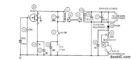
Uses 1-MHz crystal oscillator with fixed-tuned tank circuit L1-C2 link-coupled to resonant measuring circuit consisting of L4, C4, C5, and unknown capacitance. Simple RF voltmeter is connected across measuring circuit as resonance indicator. 04 and C5 have calibrated dials reading directly in picofarads. L1 is Miller 20A224RBI slugtuned unit adjusted to 250 μH. L4 is Miller 41A685CBI adjusted to 60 pH. Links L2 and L3 are 2turnseachJfo use, close S1, set C5 to maximum, and adjust C4 for peak deflection of Ma.Connect unknown capacitance to XX with shortest possible leads, retune CS to resonance, then subtract this capacitance reading of C5 from maximum reading to get value of un known capacitor.-R. P. Tumer, FET Circuits, Howard W.Sams, Indianapolis, IN, 1977,2nd Ed,p 140-142. (View)
View full Circuit Diagram | Comments | Reading(809)
AUDIO_FILTER_ANALYZER
Published:2009/7/10 21:03:00 Author:May
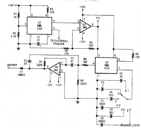
When this circuit is connected to a filter and an oscilloscope, the scope displays the ftlter's frequency response. A frequency that sweeps from low to high is applied to a filter. An oscilloscope is triggered by the start of the sweep and ends its trace at the highest frequency of the sweep. The ftlter output goes to the vertical amplifier of the oscilloscope. Using bandpass filters as an example, as the bandpass frequency is approached, reached, and paqsed, the scope follows the peaking output and draws the response curve.A neat effect!
The 566 VCO (U1) produces a VLF triangle wave to frequency modulate the next stage. It also pro-duces a square wave to externally trigger the scope. Op amp U2 (a 741 unit) optimizes the amplitude and the dc component. Another VCO (U3) produces the actual sweeping triangle wave. Its frequency is select-able via S1. Op amp U4 (another 741 op amp) is set up as a bandpass ftlter and has been included as an example filter. Finally, diode D1 chops off the bottom half of the output, and leaves a nice bell curve.
To set up and operate, power-up the circuit and scope. Set the scope's TIME/CM to 50 ms/cm. Set the VOLTS/CM control to 2V. Attach a probe from the circuit's trigger to the scope's external trigger input. Set the triggering mode to normal, external. Attach a probe from the vertical amplifier to TP1. You'll see a diagonal line that nms across the CRT. Input coupling should be set to dc. Adjust the triggering level until the diagonal runs from the upper left to the lower right of the CRT to ensure a displayed sweep from low to high. Now, disconnect the probe from TP1 and attach it to the filter output past the diode. (View)
View full Circuit Diagram | Comments | Reading(1318)
DIFFERENTIAL_TH_ERMOMETER
Published:2009/7/10 20:56:00 Author:May
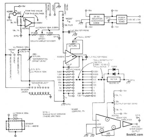
Temperatu re is directly dialed out on five-decade Kelvin-Varley voltage divider, and differences between dialed temperature and that of YS144018 sensor are read directly on meter. Full-seale sensitivity of meter is varied from 0.001 to 50℃ by adjusting gain of AD261K chopper-stabilized null detectorwhich drives both meter and AD275J isolation amplifier used to drive strip-chart recorder. Circuit can also be used to measure temperature difference between two sensors with 100-microdegree accuracy. Article describes other measuring modes as well, includ-ing techniques for measuring 200-nanodegree temperature shifts.-J. Williams, Designer's Guide to: Temperature Measurement, EDN Magazine, May 20, 1977, p 71-77. (View)
View full Circuit Diagram | Comments | Reading(1155)
LOW_COST_STEREO_PHONOGRAPH
Published:2009/7/10 6:20:00 Author:May
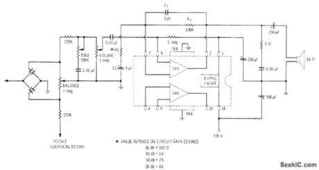
Uses single Sprague ULN-2277 IC containing two audio amplifiers each capable of driving loudspeaker directly, for input from high-impedance stereo cartridge Connections are identical for other channel,Power output per channel is 2 W. Tone and volume controls ale ganged, with those for other channel, but balance control shown serves both channels.-E. M. Noll, Linear IC Principles, Experiments, and Projects, Howard W. Sams, Indianapolis, IN, 1974, p 237-239. (View)
View full Circuit Diagram | Comments | Reading(839)
PLL_STEREO_FM_DEMODULATOB
Published:2009/7/10 6:19:00 Author:May
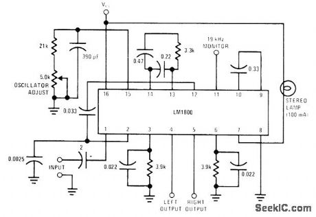
National LM1800 IC uses phase-locked loop techniques to regenerate 38-kHz subcarrier. Automatic stereo/monaural switching is included. Supply voltage range is 10-18 V.- LM1800 Phase Locked Loop FM Stereo Demodulator, National Semiconductor, Santa Clara, CA, 1974. (View)
View full Circuit Diagram | Comments | Reading(1018)
PLL_DECODER
Published:2009/7/10 6:19:00 Author:May
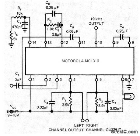
Motorola MC1310 phase-locked loop stereo decoder requires only one adjustment, by 5K pot R5. With pin 2 open, adjust R5 until reading of 19.00 kHz is obtained with frequency counter at pin 10. Alternatively, tune to stereo broadcast and adjust R5 to center of lock-in range of stereo pilot lamp. Circuit gives 40-dB separation and about 0.3% total harmonic distortion.-B. Korth, Phase-Locked Loop Stereo Decoder is Aligned Easily, EDN Magazine, Jan. 20, 1973, p 95. (View)
View full Circuit Diagram | Comments | Reading(2697)
LOUDSPEAKER_PHASING
Published:2009/7/10 6:18:00 Author:May
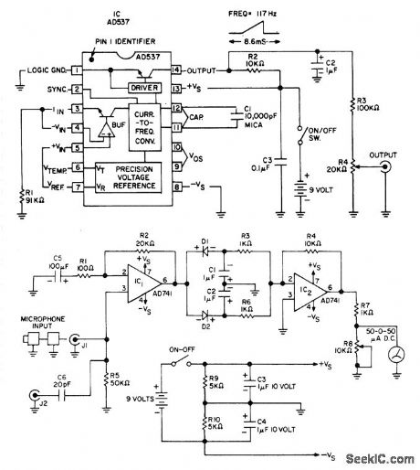
Used to determine correct phasing of loudspeakers, microphones, amplifiers, and audio lines in complex stereo systems. Transmitter input feeds sawtooth waveform into stereo input jack of one channel, and receiver unit having microphone input and zero-center meter output is held in front of each loudspeaker in turn for same channel. Components are correctly phased when meter deflects in same direction for all loudspeakers. Procedure is then repeated for other channel. Saw-tooth waveform is generated by Analog Devices AD537 JD voltage-to-frequency converter. Microphone can be that used with portable cassette recorder. 741 opamp IC1 with gain of 200 feeds dual peak detector D1-D2. Filtered DC signals are detected ramp and detected spike, with spike overriding ramp. Resulting DC level is amplified by 741 opamp having gain of 10, for driving meter. Microphones to be phased are plugged into J1 and connections noted for giving correct meter deflection. J2 is used for phasing amplifiers, lines, and other audio components. Article covers calibration and use.-C. Kitchin, Build an Audio Phase Detector, Audio, Jan. 1978, p 54 and 56-57. (View)
View full Circuit Diagram | Comments | Reading(973)
FM_DEMODULATOR
Published:2009/7/10 6:16:00 Author:May
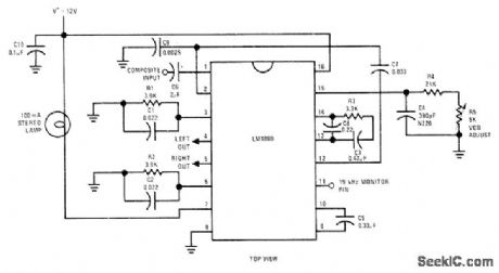
National LM1800 PLL IC accepts composite IF output and converts it to separate audio signals for left and right channels C8 has effect of shunting phase litter to minimize channel separation problems. If free-running frequency of VCO is set at precisely 19kHz with R5, separation remains constant over wide range of composite input levels, signal frequencies, temperature changes, and drift in component values,-“Linear Applications, vol. 2,” National Semiconductor, Santa Clara, CA, 1976, AN-81, p 7-8. (View)
View full Circuit Diagram | Comments | Reading(3901)
ACTIVE_TONE_CONTROLS_USING_FEEDBACK
Published:2009/7/10 6:15:00 Author:May
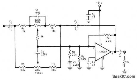
Variation of Baxandall negative-feedback tone control circuit reduces number of capacitors required. Developed for stereo systems. R4 and R5 provide negative input bias for opamp, while C0 prevents DC voltages from being fed back to tone control circuit. For other supply voltages, R4 is only resistor changed; design procedure is given.- Audio Handbook, National Semiconductor, Santa Clara, CA, 1977, p 2-40-2-49. (View)
View full Circuit Diagram | Comments | Reading(3761)
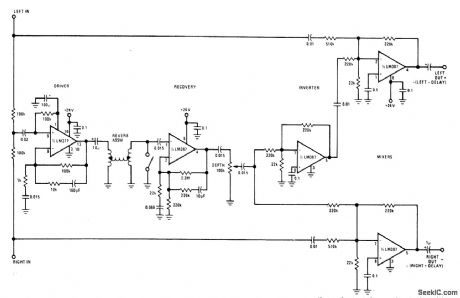
REVERBERATION_ENHANCEMENT
Published:2009/7/10 6:14:00 Author:May
Can be used to synthesize stereo effect from monaural source or can be added to existing stereo sys-tem. Requires only one spring assembly, which can be Accutronics 4BB2CIA. All opamps are National LM387 low-noise dual units. Outputs are inverted scaled sums of original and delayed signals; left output is left signal minus delay, while right output is right signal plus delay. With mono source, both inputs are tied together and outputs become input minus delay and input plus delay.- Audio Handbook, National Semiconductor, Santa Clara, GA, 1977, p 5-7-5-10. (View)
View full Circuit Diagram | Comments | Reading(777)
| Pages:205/471 At 20201202203204205206207208209210211212213214215216217218219220Under 20 |
Circuit Categories
power supply circuit
Amplifier Circuit
Basic Circuit
LED and Light Circuit
Sensor Circuit
Signal Processing
Electrical Equipment Circuit
Control Circuit
Remote Control Circuit
A/D-D/A Converter Circuit
Audio Circuit
Measuring and Test Circuit
Communication Circuit
Computer-Related Circuit
555 Circuit
Automotive Circuit
Repairing Circuit