
Index 204
DYNAMIC_FOCUS_CORRECTION
Published:2009/7/10 21:53:00 Author:May
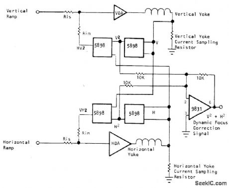
Provides sum of squares of vertical and horizontal position voltages, as required for focus correction in high-resolution flat-face magnetically deflected CRT. Circuit uses Optical Electronics 5898 fourquadrant analog multipliers to give required squared outputs, along with 9831 opamp having comparable bandwidth. Input summing resistors forhorizontal and vertical, deflection am plifiers are chosen for compatibilitj with amplifiers being used. Select current-sampling resistors to generate 10-V peak signaL- Dynamic Focus Correction with Analog Function Modules, Optical Electronics, Tucson, AZ, Application Tip 10127. (View)
View full Circuit Diagram | Comments | Reading(707)
TRACE_QUADRUPLER
Published:2009/7/10 21:52:00 Author:May
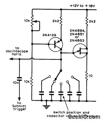
Designed for use with DC oscilloscopes. Constant-current UJT oscillator produces linear sawtooth for triggering Schmitt trigger and serving as hodzontal sweep voltage. Frequency is varied by switching capacitors, and can be up to about 100 kHz. Emitter-follower may have to be added to UJT output to prevent loading of timing capacitors by low impedance of Schmitt trigger. Used to quadruple maximum time-base frequency of oscilloscope.-J. A Titus. Trace Quadrupler, Wireless World, Oct. 1972, p 479. (View)
View full Circuit Diagram | Comments | Reading(863)
OUTPUT_STABILIZER
Published:2009/7/10 21:51:00 Author:May
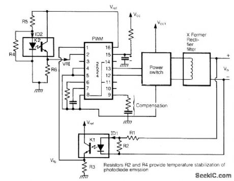
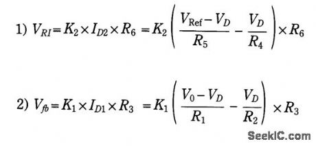


Optically isolated SMPS and dc-to-dc converters face the variance of output voltage owing to the change of transmission characteristics of an optoisolator with (a) temperature and (b) aging. The photo diode emission decays with temperature and time, and causes the output voltage to change. The problem is solved using a homoeopathic principle. An additional optical isolator is used to derive the +Ve input volt-age, instead of a conventional potential divider from internally stabilized reference. A scheme is shown using IC2524 as PWM element:where VD=forward drop of a photo diode. In equations 1 and 2, the terms:decrease with temperature. Thanks to -Ve, temperature coefficient of VD any changes in K1, and K2, as a result of temperature and aging, track each other to maintain the output voltage constant. With proper selection of R2 and R, the output voltages are found to vary by less than 0.01%/℃ over a wide tempera-ture range. (View)
View full Circuit Diagram | Comments | Reading(622)
YAMPLIFIER_WITH_10_MHz_BANDWIDTH
Published:2009/7/10 21:51:00 Author:May
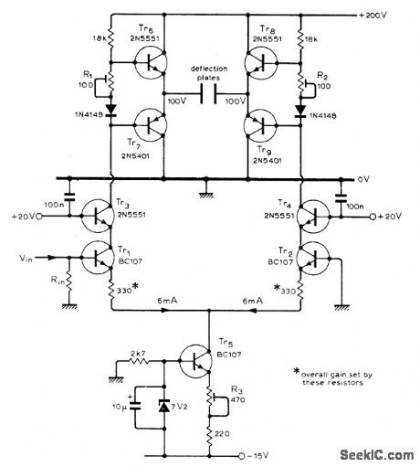
Rise time is 40 ns. Tr1-Tr4 form constant-current tail, with Tr5 improving linearity. Tr6 and Tr7 are complementary emitter-followers, as also are Tr8 and Tr9, for feeding deflection plates. Input should be from 50-ohm source to achieve full bandwidth. Other complementary small-signal transistors rated above 200 V can be used.-B.J. Frost, Wideband Y Amplifier for Oscilloscope, Wireless World, June 1976, p 71. (View)
View full Circuit Diagram | Comments | Reading(869)
REMOITE_CONTROLLED_TELEPHONE_FAX_MACHINE_SWITCH
Published:2009/7/10 21:50:00 Author:May
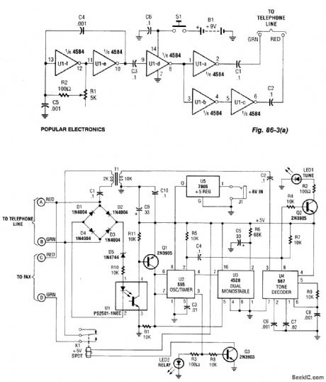
This system uses a transmitter at around 100 kHz (see Fig. 86-3(a)) to control a remote receiver. A line splitter can be used to connect the transmitter to the telephone line in use. The transmitter is a CMOS oscillator and has output buffer stages to drive the telephone line.When the receiver (Fig. 86-3(b)) detects the off-hook condition (the line voltage drops from about 48 V to less than 10 V). Optocoupler U1 has the LED extinguished. This enables timer U2. When the transmitter is activated, tone decoder U4 detects the 100-kHz signal and outputs a low signal, which lights indicator LED1. LED1 is also used to set the transmitter frequency. Also, U2 is triggered. U2 is configured for the latching condition. U2 feeds the base of Q3, turns it on and energizes relay K1, which switches in the fax machine to the telephone line.U3 prevents U2 from being accidentally triggered by transients on the telephone line. When the phone is lifted off-hook and it resets U2 after about one or two seconds of delay, transients are allowed to subside before U2 is reset, and it waits for a negative pulse on pin 2 to turn on. When U2 turns on, Q3 is biased on, which activates change-over relay K1. (View)
View full Circuit Diagram | Comments | Reading(1174)
PENTODE_CHOPPER
Published:2009/7/10 21:50:00 Author:May
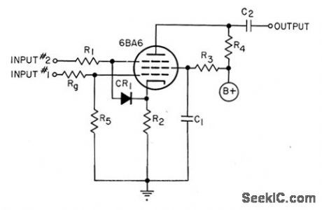
Designed for use as first stage of wide-band amplifier(d-c up to several kc).Design procedure is given.For 150V plate supply,typical values are R2=100ohms.R4=5K,R3=110K,R1=15K with 1N34A diode,R5=1meg,Rg=1K,and C1 depends on lowest frequency to be amplified.-D.G.Knox,Electronic Chopper,EEE,10:11,p 27-28. (View)
View full Circuit Diagram | Comments | Reading(664)
Y_AMPLIFIER_FOR_CRO
Published:2009/7/10 21:45:00 Author:May
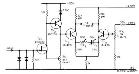
Combines advantages of differential output stage and high-impedance JFET input stage. Silicon input diodes provide crude overload protection for input, while Tr2 acts with Tr1 for level-shifting as well as amplifying. R1 is used to set quiescent output voltage of Tr2 at about 15 V; this setting is critical, and may require multitum pot. Article gives setup procedures.-G. A. Johnston, Deflection Amplifier for Oscilfoscopes, Wireless World, April 1975, p 175. (View)
View full Circuit Diagram | Comments | Reading(1060)
05_W_AF_IC
Published:2009/7/10 21:44:00 Author:May
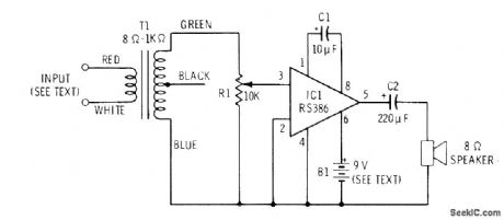
Simple audio power stage drives8-ohm loudspeaker for producing greater volume with pocket radio or for intercom applications. Supply range is 4-12 V. For long life, 6-V lantern batteries are recommended. Transformer is Radio Shack 273-1380.-F. M. Mims, Inteqrated Circuit Projects, Vol. 5, Radio shack;, Fort Worth, TX, 1977, 2nd Ed., p 38-44. (View)
View full Circuit Diagram | Comments | Reading(1820)
FIVE_RANGES_TO_1μF_WITH_TIMERS
Published:2009/7/10 21:37:00 Author:May
Based on fact that output pulse width of 555timer varies linearly with value of timing capacitance used. If timer is triggered with constant frequency, average DC value of resulting pulse train is linear function of pulse width. DC meter then reads capacitance values linearly. Decade capachance ranges are obtained by switching value of timing resistor. Trimpot for each range is adjusted for zero meter reading when push-button is pressed, without test capacitor,-C. Hall, Simplified Capacitance Meter, Ham Radio, Nov. 1978, p 78-79. (View)
View full Circuit Diagram | Comments | Reading(577)
DUAL_TIMER_MEASURES_C
Published:2009/7/10 21:37:00 Author:May
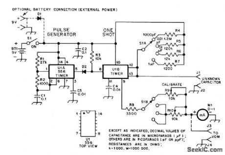
One section of U1 (two 555s in single package) is connected as oscillator that serves as trigger for other section (U1B). Ratio of R1 and R2 determines length of pulse generated during each oscillation cycle, while C1 and same resistors set frequency at about 500 Hz. U1B produces predetermined-duration output pulse for each start pulse regard-less of starting pulse length. Pulse duration is set by R4-R7 and external capacitor being measured. Smaller capacitor in given range produces shorter output pulse from U1B mono MVBR. Average pulse power increases with pulse length and increases meter reading linearly so capacitance value is indicated directly.Values shown give ranges of 1000 pF, 0.01 μF, 0.1μF, and 1 μF full-scale. R10 serves as calibration resistor for all three higher scales. D1 is 50-PIV or higher silicon power-type diode, and D2 is 1N914 or equivalent.-D. A. Blakeslee, An inexpensive Capacitance Meter, OST, Sept.1978, p 11-14 and 37. (View)
View full Circuit Diagram | Comments | Reading(646)
05_pF_TO_0001μF_COMPARATOR
Published:2009/7/10 21:32:00 Author:May
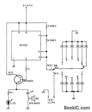
Provides audio-tone comparison of built-in reference capacitor to unknown capacitor connected between test clips. Frequency of tone is about 8 kHz for 0.5 pF, dropping to 100 Hz as capacitor value goes up to 0.001μF. Larger capacitor values merely turn LED on and off; 0.1 μF gives flashing atabout 5 Hz. Any NPN audio orswitching transistorcan be used in place of MPS6512. Suggested reference values for capacitor bank are 0.7, 3, 5, 10, 25, 50, 100, 330, 470, 680, and 820 pF.-W. Pinner, The Capacitor Comparator, 73 Magazine, March 1977, p 49. (View)
View full Circuit Diagram | Comments | Reading(598)
C_BY_GRID_DIP
Published:2009/7/10 21:31:00 Author:May
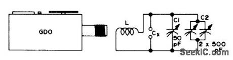
Values of unknown capaci-tances up to about 1000 pF can be measured with simple circuit used with griddip oscillator.Coil L can be 6 turns of stiff wire, To calibrate, close variable capacitors C1 and C2 fully, tune for dip, and note dip frequency at pointer position of C2. Now connect known capacitors up to 1000 pF one by one to CX, retune C2 for dip, and mark capacitor value on C2 dial. Close C2, then repeat calibration for C1 while using smaller capacitors up to 50 pF.-F, G. Rayer, GDO to Find C, 73 Magazine, Aug. 1974, p 35. (View)
View full Circuit Diagram | Comments | Reading(564)
12-V_AUTO_POWERED_CIRCUIT_FOR_CASSETTE_RECORDERS
Published:2009/7/10 21:31:00 Author:May
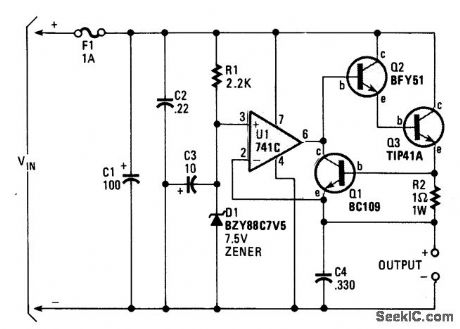
A regulator allows you to power a 7.5-V cassette recorder or other device from a 12-Vdc auto system. About 600 mA is available from the circuit. Q3 should be heatsinked because it dissipates up to 4 W. F1 should be a slow-blow fuse so that the surge caused by C1 does not cause unnecessary fuse failures. (View)
View full Circuit Diagram | Comments | Reading(629)
00001_TO_1_μF_IN_F0UR_RANGES
Published:2009/7/10 21:29:00 Author:May
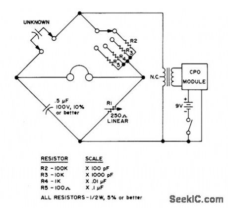
SimpIe bridge uses AF voltage from Cordover CPO-4 code practice oscillator module, fed through transistor output transformer connected in reverse for impedance matching. Earphones serve as null detector, but amplifier can be added for greater sensitivity or CRO used. Only one scale need be calibrated, using known values of capacitors.-W. P. Tumer, Build a Basic Bridge, 73Magazine, Nov. 1974, p 95. (View)
View full Circuit Diagram | Comments | Reading(564)
AUDIO_POWERED_TAPE_RECORDER_CONTROLLER
Published:2009/7/10 21:26:00 Author:May
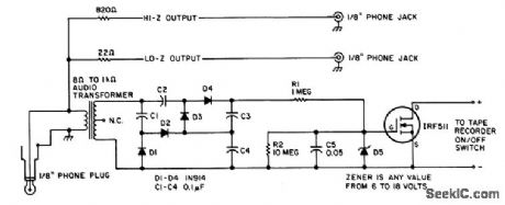
A tape recorder can be controlled by rectifying the audio input and driving an IRF511 power MOSFET to switch a tape recorder on when audio is present. This circuit was used with a communications receiver to record intermittent transmissions (such as aircraft, repeater output. etc.). (View)
View full Circuit Diagram | Comments | Reading(775)
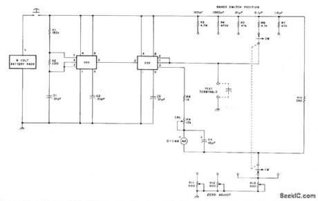
ELECTROLYTICS_WITH_REFORMING
Published:2009/7/10 21:24:00 Author:May
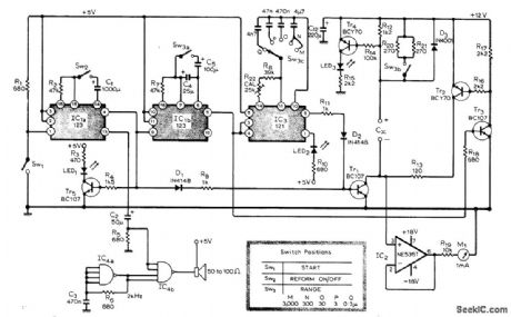
Automatic tester for electrolytics applies voltage for about 15 s to repolarize dielectric before measurement is made. This provides sufficient reforming for test purposes, using 12 V through 1200 ohms, but test should be repeated if leakage current is high because of incomplete re forming. Tone from loudspeaker indicates end of 15-s reforming period. Green LED, indicates reforming process is readyto start. Red LED, indicates excessive current is flowing during reforming. LED, flashes to indicate test capacitor is being charged during measuring cycle. Article covers construction and calibration in detail. IC, is SN74123N, IC, is SN74121N, and IC, is SN7413N.-A. Drummond-Murray, Electrolytic Capacitor Tester, Wireless World, May 1977, p 47-49. (View)
View full Circuit Diagram | Comments | Reading(1540)
TEMPERATURE_TO_PULSE_WIDTH
Published:2009/7/10 21:24:00 Author:May

Temperature-dependent current through thermistor TH1 develops voltage across R1 that is compared with fraction of increasing voltage across C1 by 741 opamp. When output of opamp goes negative, it triggers 555 IC connected as mono MVBR, to turn transistor on for about 100 μs and discharge C1. Circuit is based on similarity between resistan ce-tem peratu re curve of ther-mistor and inverse function of voltage across capacitor charging through resistor. For values shown, circuh gives 650-μs pulse width at 0℃, increasing 20 μs per degree with accuracy of ±1.2℃ up to 60℃. If IC output is used to gate clock oscillator, number of oscillator output pulses will be directly proportional to temperature.-T. P. Y. Sander, Temperature to PulseLength Converter, Wireless World, Jan. 1977, p 76. (View)
View full Circuit Diagram | Comments | Reading(1476)
NOVEL_METRONOME
Published:2009/7/10 21:23:00 Author:May
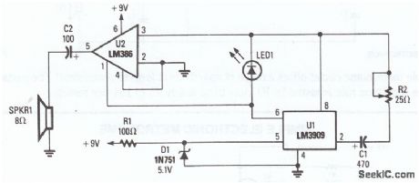


The LM3909 is conftgured so that the frequency of oscillation is dependent on a single RC timing circuit, which consists of C1 and R2. LED1 discharges capacitor C1 and the resultant pulse is directed into pin 3 as well as pin 1 of the LM386 audio amplifier to extemally control that unit, thereby providing ade-quate volume. The circuit, as it is configured, provides frequency ranges from 57 to 204 beats per minute, and plenty of volume. (View)
View full Circuit Diagram | Comments | Reading(657)
PERFECT_CAPACITOR
Published:2009/7/10 21:22:00 Author:May
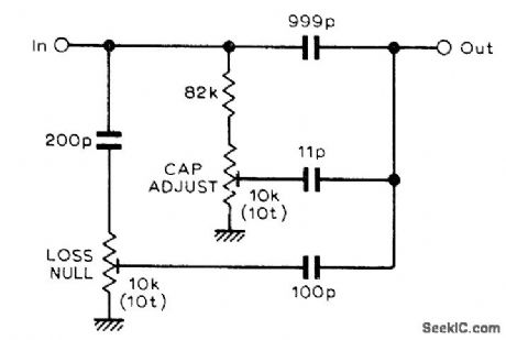
Simple circuit shown provides equivalent of perfect no-loss 1000-pF capacitor at frequencies below about 100 kHz.Principle can be used to construct fixed-fre-quency capacitance standards for use in high-accuracy capacitor bridge. All capacitors are silver mica. If mounted in oven, stability can be 1 PPM and residual phase-angle difference from pure capacitance only 1 microradian.-B. J.Frost, No Loss Capacitor, Wireless World, Dec. 1977, p 80. (View)
View full Circuit Diagram | Comments | Reading(1002)
THERMOMETER
Published:2009/7/10 21:21:00 Author:May
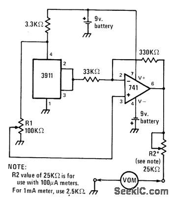
Sensor is 3911 ICwhoseout-put is 10 mV/K (kelvin temperature scale). At 0℃, output is 2.73 V. Output swing is amplified by 741 opamp to 0.1 V/℃ for driving volt-ohm-milliammeter or sensitive milliammeter. R2 ad-iusts scaling factor, for readout in ℃ or °F as de-sired.-J. Sandier, 9 Projects under $9, Modern Electronics, Sept. 1978, p 35-39. (View)
View full Circuit Diagram | Comments | Reading(792)
| Pages:204/471 At 20201202203204205206207208209210211212213214215216217218219220Under 20 |
Circuit Categories
power supply circuit
Amplifier Circuit
Basic Circuit
LED and Light Circuit
Sensor Circuit
Signal Processing
Electrical Equipment Circuit
Control Circuit
Remote Control Circuit
A/D-D/A Converter Circuit
Audio Circuit
Measuring and Test Circuit
Communication Circuit
Computer-Related Circuit
555 Circuit
Automotive Circuit
Repairing Circuit