
Index 217
TIME_OUT_WARNING_1
Published:2009/7/20 2:22:00 Author:Jessie
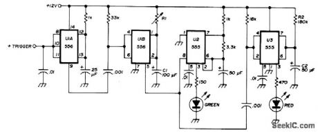
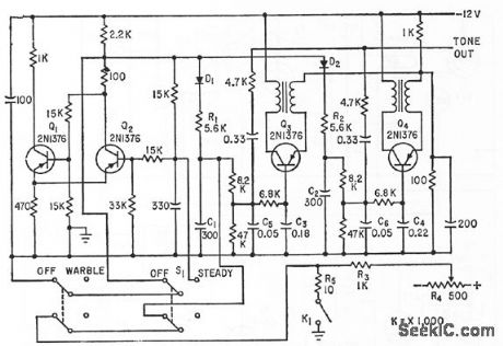
Transceiver-actuated circuit inhibits FM repeater timer override. Uses 556 dual timer and two 555 timers. Triggers on positive step-input voltage from transceiver when PTT switch is pushed. If negative triggering is preferred, omit U1A. Values of R1 and C1 provide delay that is 10 s less than repeater timer. With 60-s repeater, delay should be 50 s.Flip-flop U2 flashes green LED80times per minute during this delay. After 50 s, U2 is disabled and U3 flashes red LED for 10 s as indication that transmission must stop to avoid timing out repeater. At end of 10 s, red LED goes out and cycle is completed. If transmission time is less than that of repeater timer, indicator is recycled when PTT switch is pressed again. R1-C1 deter-mine green flash time, and R2-C2 determine red flash time.-H. M. Berlin, Time-Out Warning Indicator for FM Repeater Users, Ham Radio, June 1976, p 62-63. (View)
View full Circuit Diagram | Comments | Reading(965)
The ABS USB data, SP205, PCM, BCM, instrument part and EBCM/EBTOM circuits of Buick-Regal
Published:2011/7/20 1:36:00 Author:Borg | Keyword: instrument part, Buick-Regal
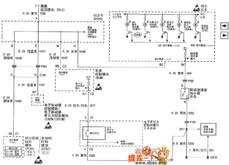
Figure 1. The ABS USB data, SP205, PCM, BCM, instrument part and EBCM/EBTOM circuits of Shanghai GM Buick-Regal
(View)
View full Circuit Diagram | Comments | Reading(894)
LIGHTNING_DETECTOR
Published:2009/7/20 2:16:00 Author:Jessie
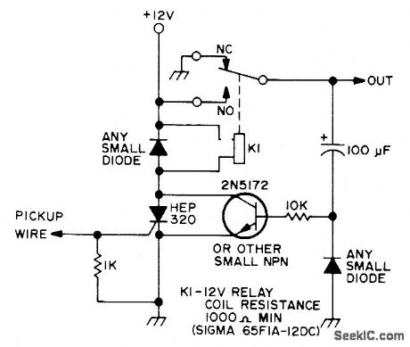
Uses 20-foot wire strung around repeater house to pick up pulses induced by lightning, Keep wire well away from antenna and transmitter. Pulse at SCR gate turns it on and energizes relay that activates signaling device at desired location. Circuit automatically resets itself after capacitor discharges through 10K resistor.-P. A. Stark, Simple Lightning Detector, 73Magazine, April 1973, p85. (View)
View full Circuit Diagram | Comments | Reading(3819)
MICROPROCESSOR_CONTROL
Published:2009/7/20 2:13:00 Author:Jessie
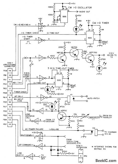
Under pro-gram control, interface for MOS Technology KIM-1 microcomputer turns on transmitter of. repeater when signal arrives at receiver; pro-vides 3-min timer, CW ID timer, and tail or delay at end of transmission; and generates Morse code CW ID. Article gives flow charts and programming for basic functions, along with complete autopatch control routine. CR1 and CR2 are small-signal silicon diodes such as 1N914, U1 and U2 are 7404 TTL hex inverters.-C, M. Robbins, The Microprocessor and Repeater Control, QST, Jan. 1977, p 30-34. (View)
View full Circuit Diagram | Comments | Reading(976)
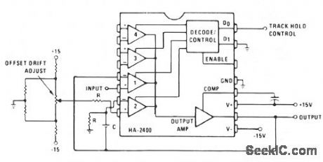
INVERTING_SAIYIPLE_AND_HOLD
Published:2009/7/9 23:29:00 Author:May
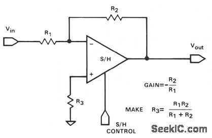
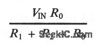
This illustrates another application in which the hookup versatility of a sample-and-hold often elimi-nates the need for a separate op amp and a sample-and-hold module. This hookup will have a some-what higher input-to-output feedthrough during hold than the noninverting connection, since the output impedance is an open-loop value during hold. The feedthrough will (View)
View full Circuit Diagram | Comments | Reading(478)
ADJUSTABLE_VOLTAGE_LIMITER
Published:2009/7/9 23:28:00 Author:May
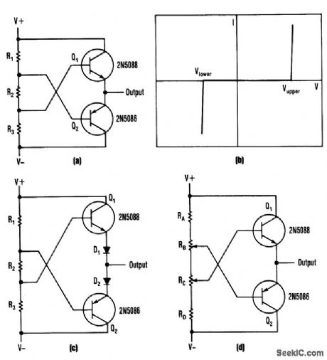
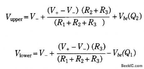
This bipolar voltage clipper can be built with two transistors, two resistors, and two potentiometers.Notice that the maximum p-p range must be ≤ BVebo of the transistors used. The design equations are:
(View)
View full Circuit Diagram | Comments | Reading(809)
READING_SAWTOOTH_CO_NTROLLING_FLIP_FLOP
Published:2009/7/20 2:08:00 Author:Jessie
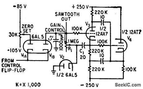
When flip-flop output is negative with respect to zero-set reference voltage, sow tooth output is dropped through diode gate to reference voltage. Start-sawtooth pulse makes output of flip-flop positive.-H. L. Daniels and D. K. Sampson, Magnetic Drum Provides Analog Time Delay, Electronics, 32:6, p 44-47. (View)
View full Circuit Diagram | Comments | Reading(566)
TRACK_AND_HOLD_SAMPLE_AND_HOLD
Published:2009/7/9 23:27:00 Author:May
Channel 1 is wired as a voltage follower and is turned on during the track/sample time. If the product of R × C is sufficiently short compared to the period of maximum output frequency, or sample time; Cwill charge to the output level. Channel 2 is an integrator with zero input signal. When channel 2 is then turned on, the output will remain at the voltage across C. (View)
View full Circuit Diagram | Comments | Reading(720)
RECORDING_SAWTOOTH_CONTROLLING_FLIP_FLOP
Published:2009/7/20 2:06:00 Author:Jessie
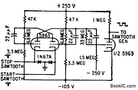
Used for sawtooth generator of magnetic drum recording system.-H. L. Daniels and D. K. Sampson, Magnetic Drum Provides Analog Time Delay, Electronics, 32:6, p 44-47. (View)
View full Circuit Diagram | Comments | Reading(514)
VU_RECORDER
Published:2009/7/20 2:05:00 Author:Jessie
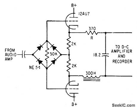
Used to provide permanent records of broadcast speech levels and for checking audio network circuits. Circuit has same rise time, overshoot, frequency response, and recliner characteristics as standard Vu meter.-D. H. McRae, Vu Recorder Has Standard Response, Electronics, 31:17, p 78-82. (View)
View full Circuit Diagram | Comments | Reading(715)
SCR_CAPACITOR_TURN_OFF_CIRCUIT
Published:2009/7/9 23:24:00 Author:May
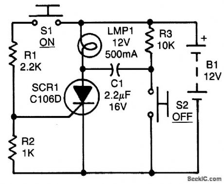
After the SCR tums on, C1 charges up to almost the full supply voltage via R3 and the anode of the SCR. When S2 is subsequently closed, it clamps the positive end of C1 to ground, and the charge on C1 forces the anode of the SCR to swing negative momentarily, thereby reverse-biasing the SCR and causing it to tum off. The capacitor's charge bleeds away rapidly, but it has to hold the SCR's anode negative for only a few ps to ensure turn-off. C1 must be a nonpolarized type. (View)
View full Circuit Diagram | Comments | Reading(1638)
CASSETTE_MOTOR_SPEED_CALIBRATOR
Published:2009/7/9 23:24:00 Author:May
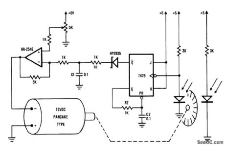
This frequency/voltage converter enables calibrations of cassette-deck speed. It records a steady 1-kHz tone on the cassette deck, and monitors the frequency on the converter. Then play the tone back and adjust the motor speed until you get the same frequency reading on the converter. The frequency/voltage converter can drive an analog meter to indicate small variations in tape speed.
(View)
View full Circuit Diagram | Comments | Reading(1940)
CHRISTMAS_LIGHT_DRIVER
Published:2009/7/9 23:23:00 Author:May
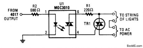
This circuit will enable a CM0S logic chip, such as a 4017 decode driver, to control a string of Christ-mas lights or other lighting. The triac should be rated at 200V and 3A or higher. The 4017 should be powered from at least 10V to ensure adequate drive to the optoisolator. (View)
View full Circuit Diagram | Comments | Reading(1271)
10000_1_KV_PULSES_PER_SECOND
Published:2009/7/20 2:03:00 Author:Jessie
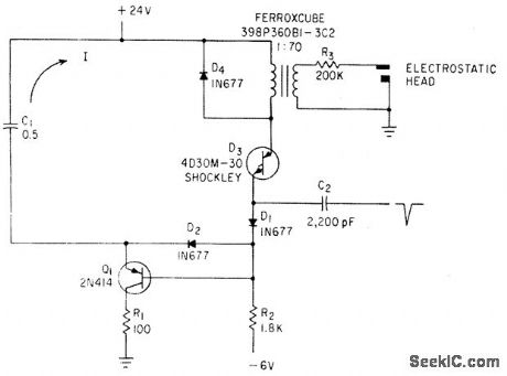
Four-layer diode D3 discharges C1 through pulse transformer and transistor Q1 prevents diode front remaining in conducting state. Used in electrographic recorder.-N. C. Hekimian and P. M. Schmitz, Four-Layer Diode Triggers High-Voltage Pulse Generator, Electronics, 34:26, p 84-85. (View)
View full Circuit Diagram | Comments | Reading(585)
TIMER_IS_AUTOPATCH_KEYER
Published:2009/7/20 2:03:00 Author:Jessie
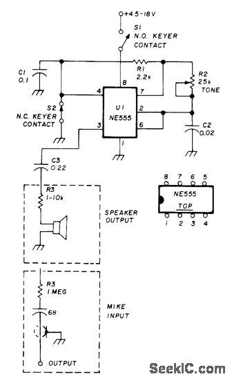
Simple keyer oscillator using NE555 timer was designed for autopatch in repeater having decoder bandpass from 2980 to 3080 Hz. Adjust R2 to 3042 Hz. 0ut-put options for loudspeaker and microphone are shown. Adjust R3 for required input/output level; use variable resistor if desired. Normally closed keyer contacts can also be connected between pin 7 and ground. Supply can be 9-V transistor radio battery.-E. Noll, Circuits and Techniques, Ham Radio, April 1976, p 40-43. (View)
View full Circuit Diagram | Comments | Reading(751)
SIX_ACCESS_TONES
Published:2009/7/20 2:02:00 Author:Jessie
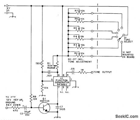
Provides 0.4-s bursts at choice of six audio frequencies, for access to up to six different repeaters. Value of C1 in transistor circuit determines duration of burst. AF oscillator uses Signetics NE566V phase-locked loop, with tone frequencies determined by C1 and R1 plus R2 through R7. To adjust initially, remove Q1 from circuit so oscillator runs continuously, connect frequency counter to junction of 0.05-pF capacitor and 1-megohm resistor, set all pots at minimum, ad just R1 for 2500 Hz, set selector switch to position 1, and adjust corresponding control for desired frequency.Repeat for other pots.-G. M. Dickson, A Tone-Burst Generator for Repeater Access, QST, April 1974, p 30-31. (View)
View full Circuit Diagram | Comments | Reading(621)
ALARM_LAMP_DRIVER
Published:2009/7/9 23:21:00 Author:May
Lamp receives power only when combination of signcds from binary stages and mvbr is correct combination of polarities to represent microwave system fctdt to be indicated by remotely located lamp.-J.B. Bullock, Pulse-Coded Foult Alarm in Microwave Systems, Electronics, 33:1, p 82-84. (View)
View full Circuit Diagram | Comments | Reading(670)
DEGLITCHER
Published:2009/7/9 23:21:00 Author:May
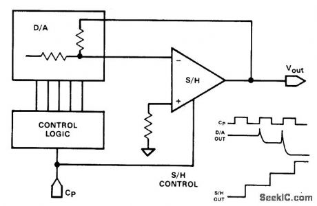
Glitch has been a universal slang expression among electronics people for an unwanted transient con-dition. In D/A converters, the word has achieved semiofficial status for an output transient, which occurs when the digital input addressed is changed. The sample/hold amplifier does double duty, serving as a buffer amplifier as well as a glitch remover, delaying the output by 1/2-clock cycle.
The sample/hold can be used to remove many other types of glitches in a system. If a delayed sample pulse is required, it can be generated using a dual monostable multivibrator IC. (View)
View full Circuit Diagram | Comments | Reading(2656)
MAGNETIC_DRUM_READ_AMPLIFIER
Published:2009/7/20 2:01:00 Author:Jessie
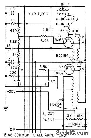
Amplifies phase-modulated step-modulated Manchester signal from magnetic drum read head and provides phase detection for recovery of stored information. Also used for synchronization.-A. J. Strassman and R. E. Keeter, Clock Track Recorder For Memory Drum, Electronics, 32:41, p 74-76. (View)
View full Circuit Diagram | Comments | Reading(568)
INDUCTIVE_LOAD_TRIAC_SWITCH
Published:2009/7/9 23:20:00 Author:May
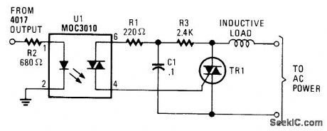
An additional resistor and capacitor enable control of an inductive load, such as a small blower motor, fluorescent lamp, etc. (View)
View full Circuit Diagram | Comments | Reading(1826)
| Pages:217/471 At 20201202203204205206207208209210211212213214215216217218219220Under 20 |
Circuit Categories
power supply circuit
Amplifier Circuit
Basic Circuit
LED and Light Circuit
Sensor Circuit
Signal Processing
Electrical Equipment Circuit
Control Circuit
Remote Control Circuit
A/D-D/A Converter Circuit
Audio Circuit
Measuring and Test Circuit
Communication Circuit
Computer-Related Circuit
555 Circuit
Automotive Circuit
Repairing Circuit