
Index 213
12_V_LATCH
Published:2009/7/10 2:06:00 Author:May
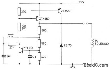
This circuit controls a solenoid by the operation of a single push-button switch. The circuit will supply loads of over 1 A and can be operated up to a maximum speed of once every 0.6 second. When power is first applied to the circuit, the solenoid will always start in its off position. Other features of the circuit are its automatic turn-off, if the load is shorted, and its virtually zero-power consumption when off. (View)
View full Circuit Diagram | Comments | Reading(806)
POWER_CONSUMPTION_LIMITER
Published:2009/7/10 2:04:00 Author:May
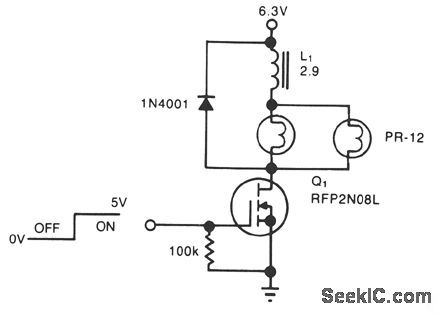


A simple solenoid driver uses incandescent lamp filaments as on-indicators to limit power con-sumption. High magnetic reluctance (opposition to flux) in the coil of an armature-driven device, such as a solenoid or relay, calls for a surge of activation current, followed by a lower dc level to remain on,since surge to on-current ratio is typically 5:1. The cold filament allows a surge of coil-activation current to pass through; as the filament heats up, it throttles the current to a more reasonable hold value. The solenoid driver circuit offers these features: ●5-V logic swings turn the power-MOSFET switch, Q1, fully on and off. ●Two low-cost flashlight lamps, in parallel, handle the peak current. Because their dc current is only 50% of peak and because they operate at 60% of their rated voltage, the lamps have an operating life of 12,000 hours. Further, the lamp filaments' positive temperature coefficients raise each filament's resistance. This rise in resistance liminates current-hogging problems and provides short-circuit protection.●The steady-state on-current is 700 mA, vs. 1700 mA without the lamps.
●A 4.6-V min supply rating allows battery opera-tion. (View)
View full Circuit Diagram | Comments | Reading(752)
_3_V_BATTERY_TO__5_Vdc_dc_CONVERTER
Published:2009/7/10 2:04:00 Author:May
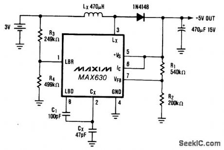
A common power-supply requirement involves converting a 2.4- or 3-V battery voltage to a 5-V logic supply. This circuit converts 3 V to 5 V at 40 mA with 85% efflciency. When IC (pin 6) is driven low, the output voltage will be the battery voltage minus the drop across diode D1. The optional circuitry that uses C1, R3, and R4 lowers the oscillator frequency when the battery voltage falls to 2.0 V. This lower frequency maintains the output-power capability of the circuit by increasing the peak inductor current, which compensates for the reduced battery voltage. (View)
View full Circuit Diagram | Comments | Reading(663)
9_TO_5_V_CONVERTER
Published:2009/7/10 2:02:00 Author:May
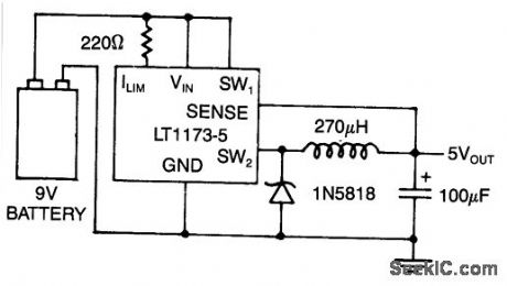
Using a Linear Technology LT1173-5, this converter produces regulated 5 V from a 9-V battery. (View)
View full Circuit Diagram | Comments | Reading(633)
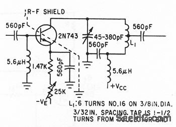
30_MC_LINEAR_SSB
Published:2009/7/10 2:02:00 Author:May
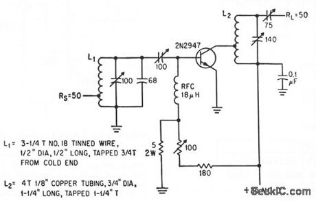
Power gain is 13 db and output is 8 w peak envelope power.-L. E.Clark, E. B. Mack, and R. C. Heihall, Highlights of Small-Signcd Circuit Design, Electronics, 36:49, p 46-50. (View)
View full Circuit Diagram | Comments | Reading(571)
1_TO_5V_dc_dc_CONVERTER
Published:2009/7/10 2:01:00 Author:May
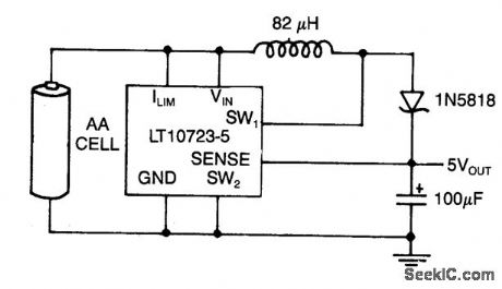
This circuit, using the Linear Technology LT1173,produces 5 V at 40 mA from a 1.5-V AA cell. (View)
View full Circuit Diagram | Comments | Reading(1495)
ELECTRONIC_SIREN
Published:2009/7/10 2:01:00 Author:May
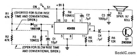
For normal wailing tone, short D1 and open R2. For fast rise and slow fall in frequency, include D1 and R2. Use of a CD4046B with a diode-RC network as shown produces a siren tone, using a VCO. (View)
View full Circuit Diagram | Comments | Reading(0)
CASCODE_MOS_FET
Published:2009/7/10 2:00:00 Author:May
Power gain is slightly higher than for neutralized commonsource stage.-G. G. Luettgenau and S. H. Barnes,Designing Wilh Low-Noise MOS FETs:A Little Different But No Harder, Electronics,37:31,p 53-58. (View)
View full Circuit Diagram | Comments | Reading(773)
AC_SOLID_STATE_RELAYS
Published:2009/7/10 2:00:00 Author:May
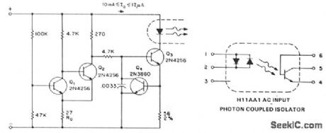
In the case where analog signals are being used as the logic control, hysteresis from a Schmitt-trigger input can be used to prevent half-wave power output. The circuit operation is as follows: at low input voltages, Q1 is biased in the off state. Q2 conducts and biases Q3, and the IRED turns off. When the base of Q1 reaches the biasing voltage of 0.6 V, plus the drop across RD, Q1 turns on. Q3 is then supplied base drive, and the solid-state relay input will be activated. The combination of Q3 and Q4 acts as a constant-current source to the IRED. In order to turn-off Q3, the base drive must be reduced to pull it out of saturation. Because Q2 is in the off-state as the signal is reduced, Q1 will now stay on to a base bias-voltage lowered by the change in the drop across RD. With these values, the highest turn-off voltage is 1.0 V, while turn-on will be at less than the 4.1 V supplied to the circuit.For ac or bipolar input signals, there are several possible connections. If only positive signals are set to activate the relay, a diode, such as the A14, can be connected in parallel to protect the IRED from reverse voltage damage, since its specified peak reverse voltage capability is approximately 3 V. If ac signals are being used, or if activation is to be polarity insensitive, a H11AA coupler, which contains two LEDs in antiparallel connection, can be used. For high-input voltage designs, or for any easy means of converting a dc input relay to ac, a full-wave diode bridge can be used to bias the IRED. (View)
View full Circuit Diagram | Comments | Reading(894)
CONSTANT_GAIN
Published:2009/7/10 1:59:00 Author:May
Differentical amplifier Q2-Q3 regulates bias of Q1 to keep gain constanl despite voriations in load or In circuit componenls.-R,C, lavigne and L.L. Kleinberg, Amplifier Gain is Constant Despite Changes in Load, Electronics, 38:13, p 75-77. (View)
View full Circuit Diagram | Comments | Reading(618)
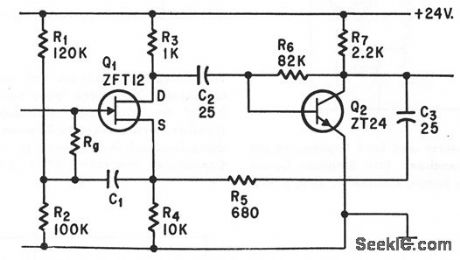
WHOOPER
Published:2009/7/10 1:58:00 Author:May
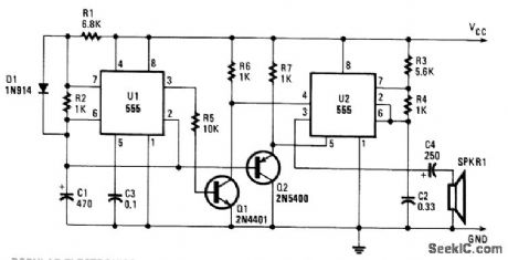
Integrated circuit U1 is connected as a low-frequency asymmetrical oscillator. Its output is inverted by Q1 and fed to the reset terminal of U2 at pin 5. Integrated circuit U2 is configured as an audio oscillator and is enabled when the output of UI is low. With the voltage at pin 5 of U2 constant, the circuit just bleeps. The voltage across capacitor C1 is fed to the base of Q2, which turns it on and grounds pin 5 of U2. When the frequency of the reset signal on pin 4 falls, the output frequency of U2 rises. The output then becomes a whoop, starting low in frequency and ending high. Resistor R1 sets the repetition rate and R2 determines the time duration of the whoop. Resistors R3 and R4 set the center-operating frequency. (View)
View full Circuit Diagram | Comments | Reading(1584)
MAGNETICALLY_CONTROLLED_IRANSISTOR
Published:2009/7/10 1:58:00 Author:May
Uncapped pnp germanium alloy junction transistor placed in strong mognetic leld shows gain variation with fiux density, with direcion and amount of gain depending on direction of magnetic leld.-R. W. Lade et al., 37:31, Magnetic Fields Vary Transistor Goin, Electronics, 34:5, p 68-70. (View)
View full Circuit Diagram | Comments | Reading(574)
50_MEG_INPUT_IMPEDANCE
Published:2009/7/10 1:58:00 Author:May
Feedback from Q2 to let Q1 boosts input impedance.-B.Down, Using Feedback in FET Circuit to Reduce Input Capacitance, Electronics,p 63-65. (View)
View full Circuit Diagram | Comments | Reading(720)
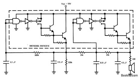
STEAM_TBAIN_WITH_WHISTLE
Published:2009/7/10 1:57:00 Author:May
View full Circuit Diagram | Comments | Reading(708)
30_MC_LOW_NOISE
Published:2009/7/10 1:57:00 Author:May

Noise figure is only 4 db for generator resistance of 200 ohms.-D. Hall, Using Epitaxial Transistors in Switching and R-F Circuits, Electronics, 34:13, p 52-53. (View)
View full Circuit Diagram | Comments | Reading(505)
TWO_STATE_SIREN
Published:2009/7/10 1:56:00 Author:May
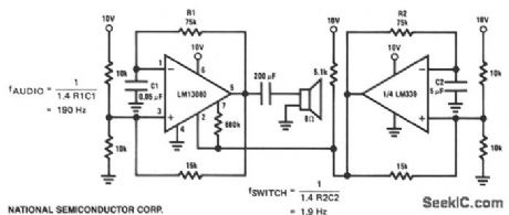
This is a two-state or on/off-type siren where the LM13080 oscillates at an audio frequency and drives an 8-0 speaker. The LM339 acts as a switch which controls the audio burst rate. (View)
View full Circuit Diagram | Comments | Reading(1555)
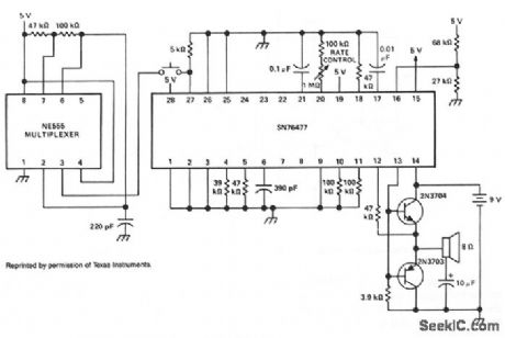
LOW_COST_SIREN
Published:2009/7/10 1:55:00 Author:May
This low-cost 1-package siren has one VCO, and the other oscillator generates the voltage ramp to vary the frequency at the VCO output. All components within the dotted line are part of the IC. (View)
View full Circuit Diagram | Comments | Reading(786)
VOLTAGE_TO_CURRENT_CONVERTER
Published:2009/7/10 1:55:00 Author:May
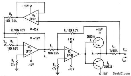
This voltage to current converter uses three op amps to drive a pair of power transistors. The current output is calculated as:
IOUT=Vin/R6
Output resistance is over 50 MΩ. IOUT can range from 1 mA to the current ratings of T1 and T2. (View)
View full Circuit Diagram | Comments | Reading(6499)
SIREN
Published:2009/7/10 1:55:00 Author:May
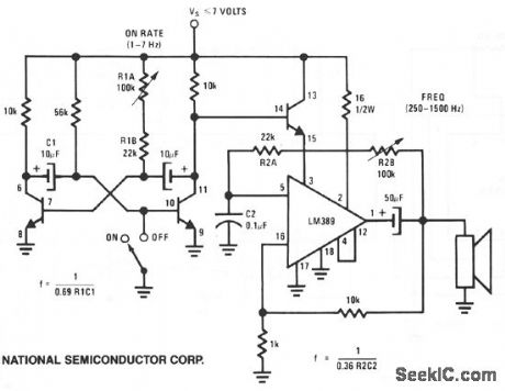
This circuit uses one of the LM389 transistors to gate the power amplifier on and off by applying the muting technique. The other transistors form a cross-coupled multivibrator circuit that controls the rate of the square-wave oscillator. The power amplifier is used as the square-wave oscillator with individual frequency adjust provided by potentiometer R2B. (View)
View full Circuit Diagram | Comments | Reading(2341)
60_MC_LOW_NOISE
Published:2009/7/10 1:55:00 Author:May
Noise figure is only 6 db for generator resistance of 150 ohms.-D. Hall, Using Epitaxial Transistors in Switching and R-F Circuits, Electronics, 34:13, p 52-53. (View)
View full Circuit Diagram | Comments | Reading(514)
| Pages:213/471 At 20201202203204205206207208209210211212213214215216217218219220Under 20 |
Circuit Categories
power supply circuit
Amplifier Circuit
Basic Circuit
LED and Light Circuit
Sensor Circuit
Signal Processing
Electrical Equipment Circuit
Control Circuit
Remote Control Circuit
A/D-D/A Converter Circuit
Audio Circuit
Measuring and Test Circuit
Communication Circuit
Computer-Related Circuit
555 Circuit
Automotive Circuit
Repairing Circuit