
Circuit Diagram
Index 1239
offset voltage adjustment non-inverting amplifier circuit
Published:2011/7/28 20:48:00 Author:John | Keyword: offset voltage adjustment, non-inverting amplifier
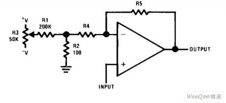
offset voltage adjustment non-inverting amplifier circuit is shown.
(View)
View full Circuit Diagram | Comments | Reading(3973)
AUTOMATIC_SHUTOFF
Published:2009/6/29 22:03:00 Author:May
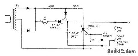
Prevents overcharging and dryout of battery under charge by shutting off automatically when battery reaches fullcharge voltage. Accepts wide range of batteries. Choose rectifying diodes and triacs or SCRs to handle maximum charging current desired. For initial adjustment, connect fully charged battery and adjust charge-stop pot until ammeter iust drops to zero.-Circuits, 73 Magazine, July 1977, p 34. (View)
View full Circuit Diagram | Comments | Reading(770)
SOLAR_POWER_OVERCHARGE_PROTECTION
Published:2009/6/29 22:02:00 Author:May
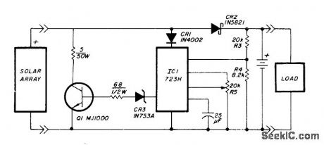
Voltage regulator is connected across solar-cell away as shown to prevent damage to storage battery by overcharging. Series diode prevents array from discharging battery during hours of darkness. Regulator does not draw power from battery, except for very low current used for voltage sampling. Battery can be lead-calcium, gelled-electrolyte, or telephone-type wet cells, For repeater application described, two Globe Union GC12200 40-Ah gelled-electrolyte batteries were used to provide transmit current of 1.07 A and idle current of 12 mA.-T. Handel and P. Beauchamp, Solar-Powered Repeater Design, Ham Radio, Dec. 1978, p 28-33. (View)
View full Circuit Diagram | Comments | Reading(3065)
SOFTWARE_CONTROL
Published:2009/6/29 21:52:00 Author:May


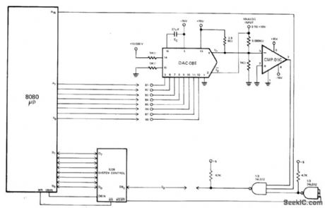
Innovative software for Intel 8080A microprocessor eliminates need for peripheral isolation devices when using Precision Monolithics DAC-08E D/A converter and CMP-01C comparator for 8-bit A/D conversion. Technique can easily be expanded to 10-bit or 12-bit conversions and adapted to other microprocessors. Logic of microprocessor replaces conventional successive-approximation register. 8 lowest-order address bits control data bit input to DAC, using software given in article.—W. Ritmanich and W. Freeman, Software Controlled Analog to Digital Conversion Using DAC-08 and the 8080A Microprocessor, Precision Monolithics, Santa Clara, CA, 1977, AN-22 p 3. (View)
View full Circuit Diagram | Comments | Reading(746)
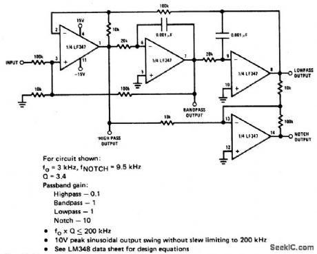
UNIVERSAL_STATE_VARIABLE_FILTER
Published:2009/6/29 21:51:00 Author:May
View full Circuit Diagram | Comments | Reading(0)
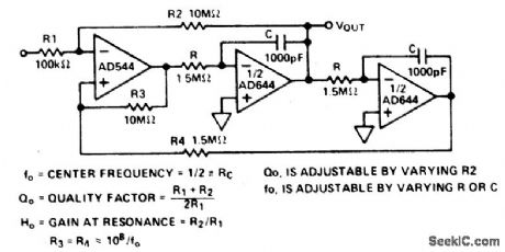
BANDPASS_STATE_VARIABLE_FILTER
Published:2009/6/29 21:50:00 Author:May
View full Circuit Diagram | Comments | Reading(717)
SELF_CONTROLLED_AUTORANGING
Published:2009/6/29 21:50:00 Author:May
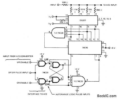
DG201 quad analog switch inserts one of four attenuator resistors in input circuit of Siliconix LD130 or comparable A/D converter under control of autoranging pulse output derived from converter. Control logic includes 74C00 quad twoinput NAND gate with two sections connected as flip-flop, 74C954-bit right-shift left-shift register, and 74C20 dual four-input NAND gate.— Analog Switches and Their Applications, Siliconix, Santa Clara, CA, 1976, p 6-28-6-29. (View)
View full Circuit Diagram | Comments | Reading(1444)
Threshold detector photodiode circuit
Published:2011/7/28 4:28:00 Author:John | Keyword: Threshold detector, photodiode
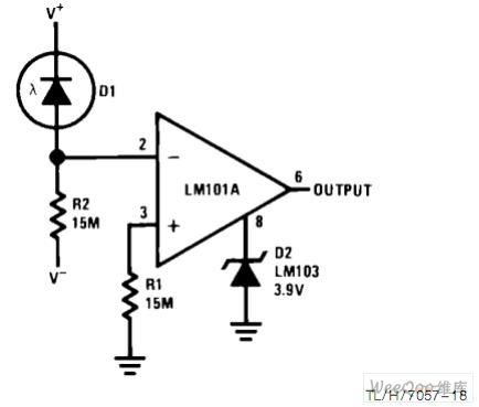
Threshold detector photodiode circuit is shown.
(View)
View full Circuit Diagram | Comments | Reading(3451)
Integrated bias current compensation circuit
Published:2011/7/28 4:25:00 Author:John | Keyword: bias current
Integrated bias current compensation circuit is shown.
(View)
View full Circuit Diagram | Comments | Reading(705)
Current-voltage converter circuit
Published:2011/7/28 4:24:00 Author:John | Keyword: Current-voltage converter

Current-voltage converter circuit is shown.
(View)
View full Circuit Diagram | Comments | Reading(2732)
non-inverting summary amplifier circuit
Published:2011/7/28 4:22:00 Author:John | Keyword: non-inverting summary amplifier
Non-inverting summary amplifier circuit is shown.
(View)
View full Circuit Diagram | Comments | Reading(1049)
inverting summary amplifier circuit
Published:2011/7/28 4:20:00 Author:John | Keyword: inverting summary amplifier
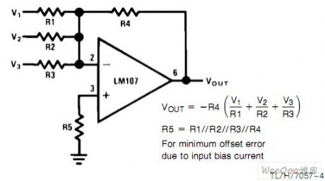
Inverting summary amplifier circuit is shown.
(View)
View full Circuit Diagram | Comments | Reading(557)
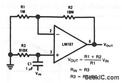
Non-inverting amplifier circuit
Published:2011/7/28 4:17:00 Author:John | Keyword: Non-inverting amplifier
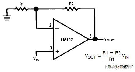
Non-inverting amplifier circuit is shown.
(View)
View full Circuit Diagram | Comments | Reading(1564)
Fast reverse amplifier with high input impedance circuit
Published:2011/7/28 4:17:00 Author:John | Keyword: Fast reverse amplifier, high input impedance
Fast reverse amplifier with high input impedance circuit is shown.
(View)
View full Circuit Diagram | Comments | Reading(729)
Current_to_voltage_converter
Published:2009/7/24 21:21:00 Author:Jessie
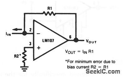
The output of this circuit is directly proportional to the input current, multiplied by the value of R1. (View)
View full Circuit Diagram | Comments | Reading(0)
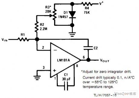
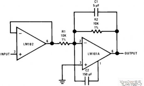
Fast_integrator
Published:2009/7/24 21:20:00 Author:Jessie
This circuit improved by about is similar to that of Fig. 10-10, except that settling time is 10 to 1. (View)
View full Circuit Diagram | Comments | Reading(1431)
Integrator
Published:2009/7/24 21:18:00 Author:Jessie
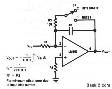
This circuit was originally developed to perform the mathematical operation of integration in analog computers. An integrator is essentially a low-pass filter with a frequency response that decreases at 6 dB per octave. When S1 is in position 1, C1 is discharged, which sets an initial condition of 0 V. With S1 in position 2, the amplifier is connected as an integrator, where the output changes in accordance with a constant times the time-integral of the input. (View)
View full Circuit Diagram | Comments | Reading(1)
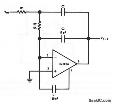
Differentiator
Published:2009/7/24 21:17:00 Author:Jessie
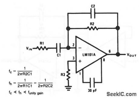
This circuit was originally developed to perform the mathematical operation of differentiation in analog computers. R2C2 form a 6-dB per octave rolloff network in the feedback, and R1/C1 for a similar network at the input making a differentiator a form of filter. The frequency fc refers to the relative frequency at unity gain, while fh refers to the frequency with a voltage gain of 20 dB. (View)
View full Circuit Diagram | Comments | Reading(0)
Noniverting_ac_amplifier
Published:2009/7/24 21:14:00 Author:Jessie
This circuit is similar to that of Fig. 10-2, except that C1 blocks dc inputs, but passes ac inputs. (View)
View full Circuit Diagram | Comments | Reading(659)
Fast_inverting_amplifier_with_high_input_impedance
Published:2009/7/24 21:14:00 Author:Jessie
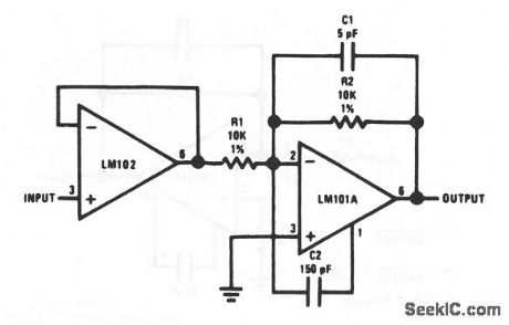
This circuit is similar to that of Fig. 10-6, except that settling time is improved by about 10 to 1. (View)
View full Circuit Diagram | Comments | Reading(0)
| Pages:1239/2234 At 2012211222122312241225122612271228122912301231123212331234123512361237123812391240Under 20 |
Circuit Categories
power supply circuit
Amplifier Circuit
Basic Circuit
LED and Light Circuit
Sensor Circuit
Signal Processing
Electrical Equipment Circuit
Control Circuit
Remote Control Circuit
A/D-D/A Converter Circuit
Audio Circuit
Measuring and Test Circuit
Communication Circuit
Computer-Related Circuit
555 Circuit
Automotive Circuit
Repairing Circuit