
Circuit Diagram
Index 1237
SOLAR_ENERGY_CHARGER
Published:2009/6/29 23:00:00 Author:May
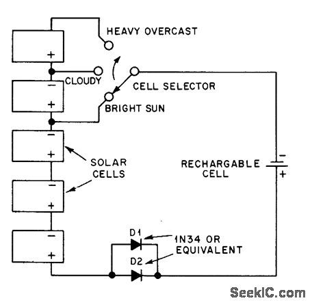
Single solar cell on bright day delivers 0.5 V at 50 mA, so three cells are used in bright sun to recharge secondary cell. Switch permits use of additional solar cells on cloudy days. Solar cells can be Radio Shack 276-128.-J. Rice, Charging Batteries with Solar Energy, OST, Sept. 1978, p 37. (View)
View full Circuit Diagram | Comments | Reading(1258)
NICAD_CHARGER_3
Published:2009/6/29 22:59:00 Author:May
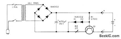
Regulated charger circuit will handle variable load from 1 to 18 nicad cells. Current-limiting action holds charging current within 1 to 2 mA of optimum value (about one-tenth of rated ampere-hour capacity) from 0 to 24 V. Q1 should have power rating equal to twice supply voltage mu ltiplied by current-limit value, lf charging 450-mAh penlight cells, charge current is 45 mA and transistor should be 2W.-A. G. Evans, Regulated Nicad Charger, 73 Magazine, June 1977, p 117. (View)
View full Circuit Diagram | Comments | Reading(1021)
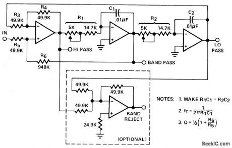
SECOND_ORDER_STATE_VARIABLE_FILTER(1_kHz,Q=10)
Published:2009/6/29 22:56:00 Author:May
View full Circuit Diagram | Comments | Reading(975)
CONSTANT_CURRENT_NICAD_CHARGER
Published:2009/6/29 22:56:00 Author:May
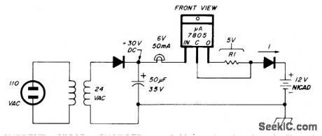
Constant current is obtained from voltage regulator by floating common line and connecting R1 from output to common terminal, Regulator then tries to furnish fixed voltage across R1. Input voltage must be greater than full-charge battery voltage plus 5 V (for 5-V regulator) plus 2 V (overhead voltage). Changing R1 varies charging curent. If R1 is 50 ohms and V is 5 V, constant current is 50 mA through nicad being charged.-G. Hinkle, Constant-Current Battery Charger for Portable Operation, Ham Radio, April 1978, p 34-36. (View)
View full Circuit Diagram | Comments | Reading(806)
BIQUAD_FILTER
Published:2009/6/29 22:54:00 Author:May
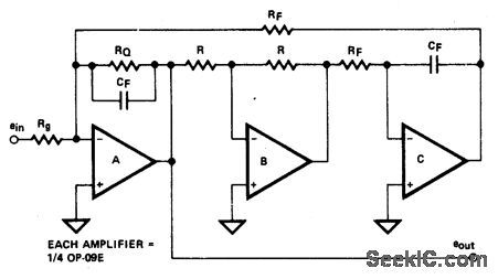
Circuit Notes
The biquad filter, while appearing very similar to the state-variable filter, has a bandwidth that is fixed regardless of center frequency. This type of filter is useful in applications such as spectrum analyzers, which require a filter with a fixed bandwidth. (View)
View full Circuit Diagram | Comments | Reading(1179)
FLASHING_LED_FOR_LOW_BATTERY
Published:2009/6/29 22:54:00 Author:May
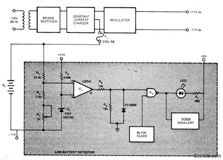
Developed for use in portable battery-operated test instrument to provide visual indication that depletion level has been reached for series arrangement of 24 nickel-cadmium cells providing 32.5 VDC for regulator of bipolar 11-V supply. Instrument must then be plugged into AC line for recharging of batteries. Voltage across B1 (nominally 32.5 V) is sensed by R1-R4 and D1. When level drops 24.1 V, opamp comparator output goes positive and enables gate IC2, so blink clock (such as low-frequency TTL-Level oscillator) makes LED flash. Audible alarm is optional.-R. T. Wamer, Monitor NiCad's with This Low-Battery Detector, EDN Magazine, April 20, 1976, p 112 and 114. (View)
View full Circuit Diagram | Comments | Reading(957)
EQUAL_COMPONENT_SALLEN_KEY_LOW_PASS_FILTER
Published:2009/6/29 22:53:00 Author:May
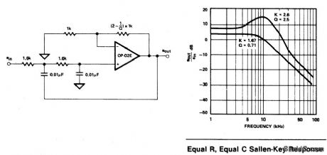
View full Circuit Diagram | Comments | Reading(760)
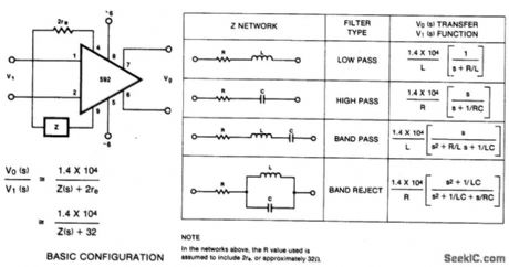
FILTER_NETWORKS
Published:2009/6/29 22:50:00 Author:May
View full Circuit Diagram | Comments | Reading(696)
AUDIO_SWITCHING_GATE
Published:2009/6/29 22:49:00 Author:May
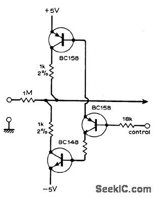
Can be used with programmed channel selectors, as required in music synthesis for controlling audio signals by means of TTL levels. DC offset at output is negligible when gate is off, simplifying design of subsequent stages. Use logic 1 (+5 V) to open gate, and logic 0 (0 V) to close it.-L. Cook, Analogue Gate with No Offset, Wireless World, Feb.1975, p 93. (View)
View full Circuit Diagram | Comments | Reading(923)
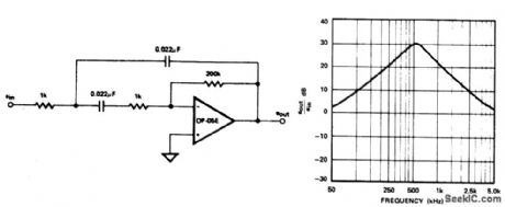
500_Hz_SALLEN_KEY_BANDPASS_FILTER
Published:2009/6/29 22:48:00 Author:May
View full Circuit Diagram | Comments | Reading(860)
PANNING_MIXER_POT
Published:2009/6/29 22:48:00 Author:May
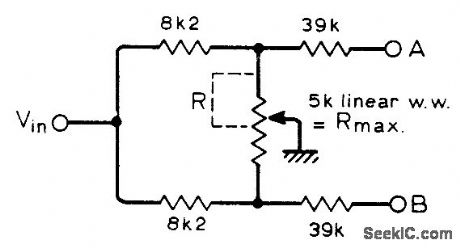
Circuit gives best possible approach to sine law so A2 = B2 is constant for all positions of wiper. Calculated error is less than n dB over full range of wiper. Use wirewound pot to minimize crosstalk.-J. Dawson, Single Gang Pan-Pot, Wireless World, Feb 1976,p78. (View)
View full Circuit Diagram | Comments | Reading(955)
18_V_MONITOR
Published:2009/6/29 22:47:00 Author:May
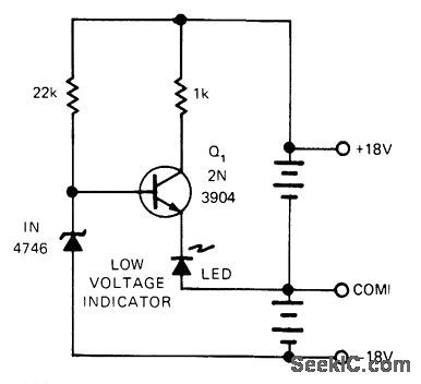
Circuit turns on LED when ±8 V battery pack discharges to predetermined low level, while drawing less than 1 mA when LED is off. Zener is reverse-biased for normal operating range of battery. When lower limit is reached, zener loses control and Q1 becomes forward-biased, turning on LED or other signal device to indicate need for replacement or recharging.-W. Denison and Y. Rich, Battery Monitor Is Efficient, yet Simple, EDN Magazine, Oct. 5, 1974, p 76. (View)
View full Circuit Diagram | Comments | Reading(893)
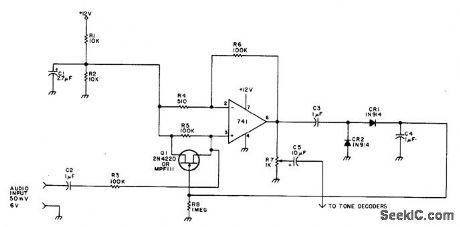
CONSTANT_AF_LEVEL
Published:2009/6/29 22:47:00 Author:May

Provides constant output level even though input may vary between 50 mV and 6V, for distribution to tone decoders of autocall system used to monitor simplex or repeater channel to which amateur radio receiver is tuned. Positive terminal of electrolytic C3 must go to pin 6 of 741.-C.W.Andreasen, Autocall '76, 73 Magazine, June 1976, p 52-54. (View)
View full Circuit Diagram | Comments | Reading(2076)
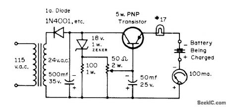
UJT_CHARGER_FOR_12_V
Published:2009/6/29 22:46:00 Author:May
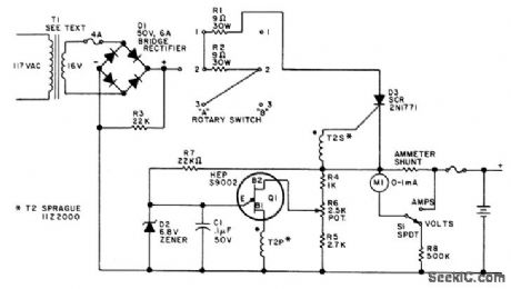
Keeps 12-V auto storage battery fully charged, for immediate standby use when AC power fails. Power trans-former secondary can be 14 to 24 V, rated at about 3 A. Two-gang rotary switch gives choice of three charging rates. Pulse transformer 72 is small audio transformer rewound to have 1:1 turns ratio and about 20 ohms resistance, or can be regular SCR trigger transformer. UJT relaxation oscillator stops when upper voltage limit for battery is reached, as set by pot R6. If oscillator fails to start, reverse one of pulse trans-former windings.-F. J. Piraino, Failsafe Super Charger, 73 Magazine, Holiday issue 1976, p 49. (View)
View full Circuit Diagram | Comments | Reading(739)
COMPANDER_WITH_100dB_RANGE
Published:2009/6/29 22:46:00 Author:May
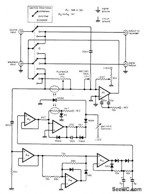
Simple squarelaw circuit preserves dynamic range of virtually any input signal when recorded by or dinary tape recorder. Suitable for speech signals as well as for recording or playback in noisy environments. Opamp A1 should have separately decoupled supply. Switching provides compression during recording and expansion during playback. Tracking of photocells is essential for accurate power-law compansion, LED can be glued with clear epoxy to matched photocells. Use silicon signal diodes such as 1N914, 1N4148, or 1S44. Inexpensive photocells such as Vactec VT-833 gave suitably low distortion. Article gives performance characteris-tics and operating details.-J. Vanderkooy, Wideband Compander Design, Wireless World, July 1976, p 45-49. (View)
View full Circuit Diagram | Comments | Reading(1274)
12_V_CHARGER
Published:2009/6/29 22:45:00 Author:May
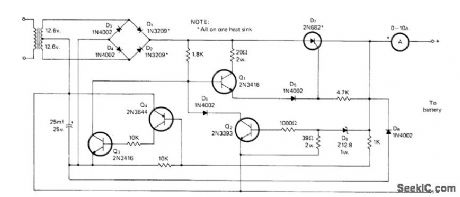
Heath GP-21 charger uses SCR as switch to connect and disconnect battery at 120-Hz rate. Voltage at anode of SCR D7 goes positive each half-cycle, putting forward bias on base of Q1 through 1.8K resistor so Q1 passes current through D5 to gate of D7 to turn it on for part of half-cycle and charge battery. D7 stays on until voltage across it drops to zero. When battery has eharged to 13.4 V, charging stops automatically. Rest of circuit protects against battery polarity reversal and accidental shorting of output leads. Special 12.8-V zener can be replaced by selected 1N4742 and forward-biased 1N4002.-H. Olson, We Don't Charge Nothin' but Batteriesl, CQ, Feb. 1976, p 25-28 and 69. (View)
View full Circuit Diagram | Comments | Reading(1336)
NICAD_CHARGER_2
Published:2009/6/29 22:43:00 Author:May
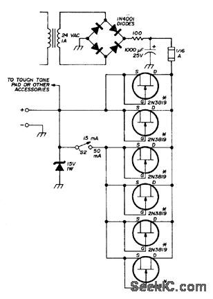
Developed for recharging small nickel-cadmium batteries used in handheld FM transceivers. Field-effect transistors serve as constant-current sources when gate is shorted to source. Practically any N-channel JFET having drain-to-source cument of 8-15 mA will work. FETs shown were measured individually and grouped to give desired choice of 15- or 50-mA charging currents.-G. K Shubert, FET-Controlled Charger for Small Nicad Batteries, Ham Radio, Aug. 1975, p 46-47. (View)
View full Circuit Diagram | Comments | Reading(759)
NICAD_CHARGER_1
Published:2009/6/29 22:42:00 Author:May
Pot is adjusted to provide 10% above rated voltage (normal full-charge voltage) while keeping charging current below 25% of maximum,For 10-V 1-Ah battery,set voltage at 11 V and current below 250 mA.-G.E.Zook, F.M., CQ,Feb. 1973, p 35-37. (View)
View full Circuit Diagram | Comments | Reading(663)
AUTOMATIC_SHUTOFF_1
Published:2009/6/29 22:41:00 Author:May
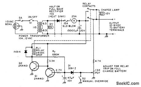
Charger automatically turns itself off when 12-V auto storage battery is fully charged. Setting of 1.5K pot determines battery voltage at which zener D1 conducts,turning on Q2 and pulling in relaythat disconnects charoer. If battery voltage drops below threshold, relay automatically connects charger again. S2 is dosed to bypass automatic control when charger itself is to be used as power supply.-G. Hinkle, The Smart Charger, 73 Magazine, Holiday issue 1976, p 110-111. (View)
View full Circuit Diagram | Comments | Reading(690)
NICAD_MONITOR
Published:2009/6/29 22:40:00 Author:May
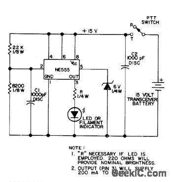
Uses two comparators, flip-flop, and power stage all in single NE555 IC. When battery voltage drops below 12-V threshold set by R1 and R2 for 15-V transceiver battery, one comparator sets flip-flop and makes output at pin 3 go high. IC then supplies up to 200 mA to LED or other indicator. For other battery voltage value, set firing point to about three-fourths of fully charged voltage. Sinqe battery voltage will show biggest drop when transmitting, connect monitor across transmit supply only so as to minimize battery drain.-A. Woemer, Ni-Cad Lifesaver, 73 Magazine, Nov. 1973, p 35-36. (View)
View full Circuit Diagram | Comments | Reading(899)
| Pages:1237/2234 At 2012211222122312241225122612271228122912301231123212331234123512361237123812391240Under 20 |
Circuit Categories
power supply circuit
Amplifier Circuit
Basic Circuit
LED and Light Circuit
Sensor Circuit
Signal Processing
Electrical Equipment Circuit
Control Circuit
Remote Control Circuit
A/D-D/A Converter Circuit
Audio Circuit
Measuring and Test Circuit
Communication Circuit
Computer-Related Circuit
555 Circuit
Automotive Circuit
Repairing Circuit