
Circuit Diagram
Index 1238
The Circuit of TV Steady Pressure Protection Used in Countryside
Published:2011/5/6 1:39:00 Author:May | Keyword: TV Steady Pressure Protection
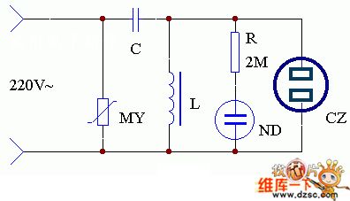
The application of this set is shown in the diagram. As the voltage of transmission network in the countryside is not very stable now, you can homemade a simple AC magnetic saturation regulator device. You can merge a varister MY in the input end of AC constant voltage regulator. It can protect the TV from overvoltage and let TV work more stable. Using the AC voltage regulator in thunderstorm days can protect the TV from striking by lightning.
(View)
View full Circuit Diagram | Comments | Reading(653)
COMPR_ESSOR_LIMITER
Published:2009/6/29 22:33:00 Author:May
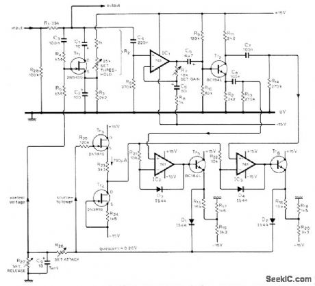
High-fidelity circuit uses voltage-controlled attenuator to increase attenuation of input signal in response to voltage of control loop. Designed for use in modern sound studios. Output-sensing amplifier using IC1 has gain of 19 over audio band. Tr2 stage is phase-splitterdriving precision rectifiers IC2 and IC3. Final part of circuit defines attenuation time constants; R26 sets attack time and R27 decay time. R26 can range from 0 to 1 megohm and R27 from 1000 ohms to infinity, using either switched or variable components. Article describes circuit operation and adjustment in detail. Tr6 is BC184L or equivalent.-D. R. Self, High-auality CompressoriLimiter, Wireless World, Dec. 1975, p 587-590. (View)
View full Circuit Diagram | Comments | Reading(867)
PREEMPHASIS_AT_1500_Hz
Published:2009/6/29 22:31:00 Author:May
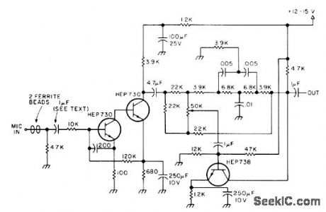
Single-transistor peaking filter is combined with low-noise RFprotected preamp stage to improve speech intelligibility for any type of modulation. Effectiveness is most noticeable with deep bass voice, where soft peak around 1500-2000 Hz improves speech intelligibility. Can also serve as audio-type CW or SSB filter-You Can Sound Better with Speech Pre-Emphasis, 73 Magazine, Feb. 1977, p 42-43. (View)
View full Circuit Diagram | Comments | Reading(1464)
HI_FI_COMPRESSOR
Published:2009/6/29 22:28:00 Author:May
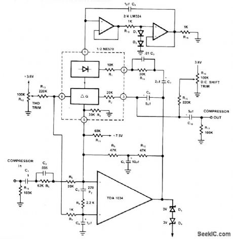
One section of Signetics NE570 dual compandor is used with extemal opamp for compression of large input signals in high-fidelity audio system. To prevent overload by sudden loud signal when compressor is operating at high gain for small signals, bruteforce clamp diodes D3 and D4 limit output swings to about 7V P-P, Limiting action prevents overloading of succeeding circuit such as tape recorder. Circuit includes input compensation network required for stability. Corresponding expander used for playback of recorded material should have same value for rectifier capacitor C9 as is used in compressor.- SignetIcs Analog Data Manual, SignetIcs, Sunnyvale, CA, 1977, p 804. (View)
View full Circuit Diagram | Comments | Reading(2337)
TWO_TUBE_WILLAMSON_OUTPUT
Published:2009/6/29 22:22:00 Author:May
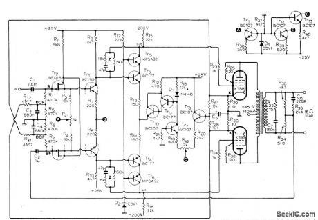
Responseis fiat from 10 Hz to over 50 kHz for outputs upto 15 W、and total harmonic distortion for full power output at 15 kHz is only 0.25%.Output stage uses tubes connected as triodes in pushpull. Input transistor can be any in Philips BFQ10-16 family or equivalent replacement such as Siliconix E401. Article gives many suitable replacements for other transistors as well, and describes desigit of required feedback cir-cuits in detail.-S. Berglund, Transistor Driver for Valve Amplifiers, Witeless World, April 1976, p 36-40. (View)
View full Circuit Diagram | Comments | Reading(1467)
INVERTING_AC_AMPLIFIER
Published:2009/6/29 22:21:00 Author:May
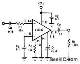
Provides gain of 40 dB when using 24-V supply and input impedance greater than 10K. Low-frequency performance is flat to 20 Hz. Design procedure is given.- Audio Handbook, National Semiconductor, Santa Clara, CA,1977, p 2-20-2-24. (View)
View full Circuit Diagram | Comments | Reading(876)
BALANCED_INPUT_MICROPHONE_PREAMP
Published:2009/6/29 22:21:00 Author:May
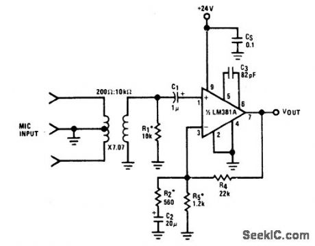
Use of two wires for microphone signal and separate wire for ground keeps hum and noise at minimum. Signal wires are twisted together in shield acting as ground. Net gain is 52 dB, giving 0-dBm output for nominal 2-mV input.Noise performance is -86 dB below 2-mV input level, and rejection of commonmode signals is 60 dB.- Audio Handbook, National Semiconductor, Santa Clara, CA, 1977, p 2-37-2-40. (View)
View full Circuit Diagram | Comments | Reading(897)
CURRENT_CONTROLLED_SWTCHING
Published:2009/6/29 22:20:00 Author:May
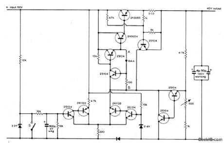
Addition of current control to 40-V regulated power supply for audio amplifier elimin ates switch-on transients that sometimes cause lilming loudspeaker thumps. Switch S,which can be either relay or third pole on standard ON/OFF switch of amplifier,is opened to initiats charging of 800-μF capacitor that allows gradual buildup of output current ,Similar transient suppression occurs when switch is closed to initiate current run-down as set is turned off,Run-up rundown times are a few seconds each,Article also tives simpler current control circuit suitable for use with unregulated supplies,-P.J.Briody,Power Supply Delayed Switching,Wirless World, March 1975, p 139-141 (View)
View full Circuit Diagram | Comments | Reading(960)
BASS_BOOST
Published:2009/6/29 22:18:00 Author:May
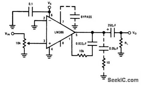
Compensates for poor bass response of loudspeaker by use of external series RC circuit between pins 1 and 5、paralleling internal 151k resistor of opamp.6-dB effective bass boost is obtained if resistor is 15K and lowest value for stable operation is 10k if pin 8 is left ope.- Audio Handbook, National Semiconductor,Santa Clara,CA,1977,p 4-30-4-33. (View)
View full Circuit Diagram | Comments | Reading(2358)
BRIDGE_AMPLIFIER_1
Published:2009/6/29 22:17:00 Author:May
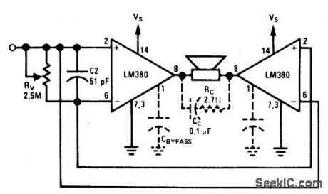
Two opamps are used in bridge configuration to provida twice the voilage swing across loudspeaker load for given 18-V supply,increasing power capability to about twice that of single amplifier.To eliminate excessive quiescent DC voltage across load,nonpolarized capacitor can be used in series with load or 1-megohm pot can be connected between pins 1 of opampswith position of moving arm adiusted to balance offset voltage Components shown with dashed Iines are added for stability with high-current load.-"Audio Handbook, National Semiconductor,Santa Clara, CA.1977,p 4-21-4-28. (View)
View full Circuit Diagram | Comments | Reading(876)
ULTRALOW_NOISE_PREAMP
Published:2009/6/29 22:16:00 Author:May
Provides gain of 1000 over bandwidth of 20 Hz to 10 kHz, operating from 24-V supply and 600-ohm source impedance. Design procedure is given. Total wideband noise voltage is 43.7μA, and wideband noise figure is 2.83 dB.- Audio Handbook, National Semiconductor, Santa Clara, CA, 1977, p 2-15-2-19. (View)
View full Circuit Diagram | Comments | Reading(1107)
IMPEDANCE_BUFFER
Published:2009/6/29 22:15:00 Author:May
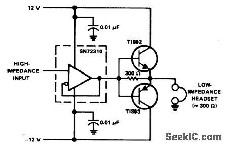
Complementary-transistor output stage provides required low impedance for driving headphones from SN72310 voltage-follower opamp. Supply is ±12V.- The Linear and Interface Circuits Data Book for Design Engineers, Texas Instruments,Dallas,TX,1973,p 4-41 (View)
View full Circuit Diagram | Comments | Reading(929)
PREAMP_IN_MIKE
Published:2009/6/29 22:10:00 Author:May
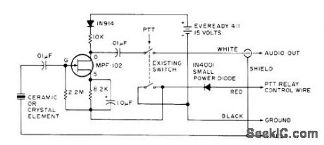
Common-source FET preamp and 15-V battery fit into Turner 3500 hand mike for boosting output of ceramic element 20 dB. Frequency response of preamp is flatfrom 200 Hz to over 100 kHz,Drain is 200 μA only when push-to-talk is pressed、giving long battery life.-G. Hinkle、 Self-Powered Mike Preamp,73 Magazine, Nov.1976,p 65 (View)
View full Circuit Diagram | Comments | Reading(983)
Homemade audio remote control circuit
Published:2011/7/28 21:04:00 Author:John | Keyword: Homemade audio, remote control
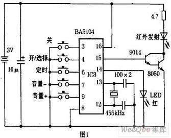
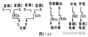
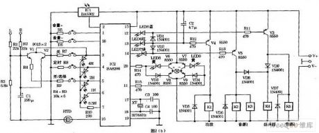
A remote control circuit has been designed for convenient use while manufacturing the sound by self. The easy purchased fan IC BA5104/BA8206 is used as the control chip. The functionality of the chip has been maximized through rational design. Due to the good performance, it can be well introduced for everyone. It can achieve the following functions: ① manual / remote control;② remote volume;③ source selection;④ delay shutdown;⑤ switch speaker protection;⑥ sound and light show. Transmitter circuit is shown in Figure 1. Receive and control circuits are shown in Figure 2. IC2 is the chip of the fan circuit.
(View)
View full Circuit Diagram | Comments | Reading(2653)
offset voltage adjustment differential amplifier circuit
Published:2011/7/28 20:50:00 Author:John | Keyword: offset voltage adjustment, differential amplifier
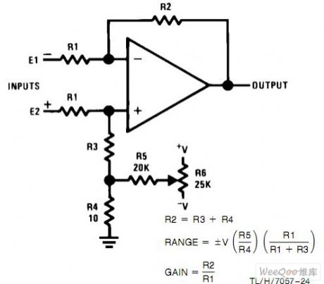
offset voltage adjustment differential amplifier circuit is shown.
(View)
View full Circuit Diagram | Comments | Reading(6003)
50_mW_FLAT_TO_30_kHz
Published:2009/6/29 22:09:00 Author:May
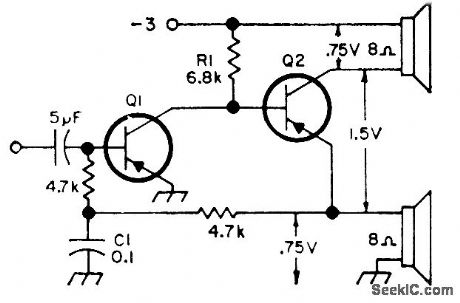
Power amplifier achieves push-pull output with single transistor. Both transistors should be germanium such as 2N404 SK3004 or HEP-253.-Circuits, 73 Magazine, Feb. 1974, p 100. (View)
View full Circuit Diagram | Comments | Reading(2128)
Offset voltage adjustment voltage follower circuit
Published:2011/7/28 20:50:00 Author:John | Keyword: Offset voltage adjustment, voltage follower
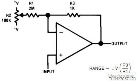
Offset voltage adjustment voltage follower circuit is shown.
(View)
View full Circuit Diagram | Comments | Reading(2883)
LOW_NOISE_OPAMP_PREAMP
Published:2009/6/29 22:07:00 Author:May
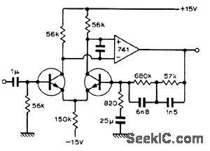
Circuit combines noise features of discrete design with simplicity and high open-loop of IC opamp such as 741. Transistors can be 2N3708, BC109, or equivalent. Output impedance is low enough to drive headphones directly.-D. R. Hedgeland, 0p-Amp Pre-Amp, Wireless World, Dec, 1972, p 575. (View)
View full Circuit Diagram | Comments | Reading(1511)
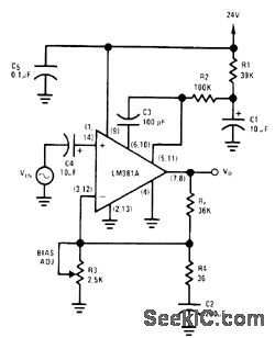
5_W_IC
Published:2009/6/29 22:06:00 Author:May
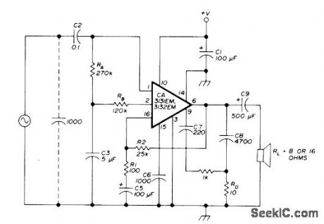
RCA IC includes preamps, power amplifier, and integral heatsink. CA3131 has internal feedback network that maintains 48-dB gain, while CA3132 requires external feedback network including R1 and R2 connected between pins 6 and 16. Input 1000-pF capacitor is required if input has open circuit. Electrolytic C1 should be placed as close as possible to pin 10,C6 sets 46-dB closed-loop gain pointat 200 kHz C7 equalizes gain for positive and negative signal swings C9 sets low-frequecy response of amplifier Recommended suppiv voltageis 24VDC,-E.Noll, Audio-Power Integrated Circults,Ham Radio、Jan 1976、p 64-66 (View)
View full Circuit Diagram | Comments | Reading(729)
BASIC_12_V_CHARGER
Published:2009/6/29 22:05:00 Author:May

Uses 200-W lamp as current-limiting resistor in transformer primary circuit. Serves in place of older types of chargers using copper-oxide or tungar-bulb rectifiers.-H.Olson, Battery Chargers Exposed, 73 Magazine, Nov.1976, p 98-100 and 102-104. (View)
View full Circuit Diagram | Comments | Reading(1293)
| Pages:1238/2234 At 2012211222122312241225122612271228122912301231123212331234123512361237123812391240Under 20 |
Circuit Categories
power supply circuit
Amplifier Circuit
Basic Circuit
LED and Light Circuit
Sensor Circuit
Signal Processing
Electrical Equipment Circuit
Control Circuit
Remote Control Circuit
A/D-D/A Converter Circuit
Audio Circuit
Measuring and Test Circuit
Communication Circuit
Computer-Related Circuit
555 Circuit
Automotive Circuit
Repairing Circuit