
Index 165
LOGIC_LEVEL_SHIFTER
Published:2009/7/16 1:30:00 Author:Jessie
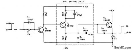
Common-emitter circuit of Q2 shifts logic level from +6.8 v to -6.8 v, with rise and fall limes of 60 nsec.Q3 is buffer.-G. Marosi, High-Speed Level Shifter, Electronics, 39:5, p 105. (View)
View full Circuit Diagram | Comments | Reading(1735)
COINCIDENCE_DECADE_COUNTER
Published:2009/7/13 23:18:00 Author:May
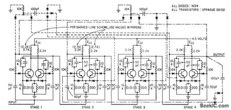
Circuit generates coincidence triggers for advancing count at any instant. Two decade schemes are shown by broken lines connected to basic counter stages. With dash-dash lines, counting proceeds in binary fashion until eighth count; at ninth count, stages 1 and 4 generate positive leading coincidence trigger and apply it to stages 2 and 3 to change them from 0 to 1, so all stages are at 1 on count 9. Next count then clears all stages to O. Dash-dot lines show coincidence for advancing the counter six units for the fourth count.-P. K. Malhotra and R. Parshad, Novel Coincidence Technique for Transistor Decode Counter, Electronics, 36:7, p 71-72. (View)
View full Circuit Diagram | Comments | Reading(843)
ISOLATED_GATE_DRIVEFOR_TRIAC
Published:2009/7/13 23:17:00 Author:May
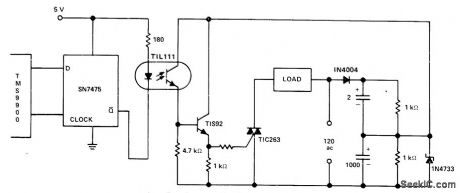
TIL111 optoisolator provides electrical isolation between control logic and gate drive for triac at low cost, with faster switching than is possible with relays. Transistor provides direct current drive for gate of triac. - Thyristor Gating for μp Applications,″Texas Instruments,Dallas,TX,1977, CA-191,p4-5.
(View)
View full Circuit Diagram | Comments | Reading(3352)
FULL_BINARY_ADDER
Published:2009/7/16 1:29:00 Author:Jessie
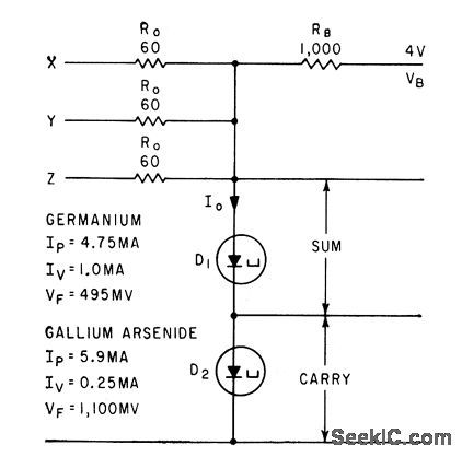
Two tunnel diodes in series perform arithmetic function of full addition.-B. Rabinovici and J. Klapper, Designing Tunnel-Diode Circuits Using Composite Characteristics, Electronics, 35:7, p 46-48. (View)
View full Circuit Diagram | Comments | Reading(747)
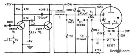
UNIVERSAL_NBS_DIODE_LOGIC_CIRCUIT
Published:2009/7/16 1:29:00 Author:Jessie
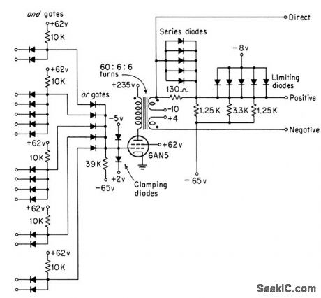
Developed National Bureau of Standards to perform all required logic perations in two computers. Uses beam power tube for amplification of 1-Mc pulses, and transformer for coupling to subsequent levels.-Y. Chu, Digital Computer Design Fundamentals, McGraw-Hill, N.Y., 1962, p 173. (View)
View full Circuit Diagram | Comments | Reading(672)
WAILING_WITCH_NOISEMAKER
Published:2009/7/13 23:15:00 Author:May
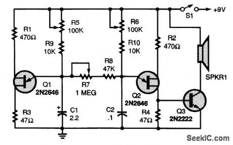
Two unijunction transistors, Q1 and Q2, are connected in a dual-oscillator circuit. Transistor Q1 is connected in a very-low-frequency relaxation oscillator circuit, with C1, R1, R5, and R9 setting the operating frequency. Transistor Q2 is connected in a similar oscillator circuit that operates at a much higher audio frequency. That oscillator's frequency is set by R6, R10, and C2. Resistor R7, a 1-MΩ potentiometer, sets the mixing level of the two oscillators. By adjusting R5, R7, and R6, many strange sounds can be created. (View)
View full Circuit Diagram | Comments | Reading(1438)
144_MHz_PREAMP
Published:2009/7/16 0:02:00 Author:Jessie
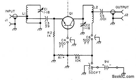
Solid-state preamplifierfor 2-m band equals performance of best tube designs. Value of R1 is chosen for optimum gain versus noise figure. Two 500-pF feedthrough capacitors (FT) serve as convenient terminals for connection. Q1 is 2N2708, 2N4936, or equivalent. Article covers construction and tune-up. C. Sondgeroth , Really Soup Up Your 2m Receiver, 73 Magazine, Feb. 1976, p 40-42. (View)
View full Circuit Diagram | Comments | Reading(1259)
150_MC_CLOCK_GATE_AND_DRIVER
Published:2009/7/16 Author:Jessie
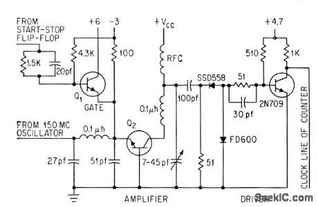
When gale transistor Q1 (2N2368) is turned on, 200-Mc bandwidth amplifier Q2 is off to provide isolation and permit switching within one cycle of dock. Driver output goes to decade counter.-L. C. Drew, Using Microcircuits in High-Resolution Range Counters, Electronics, 36:47, p 31-33. (View)
View full Circuit Diagram | Comments | Reading(628)
TWO_OUTPUT_SQUARE_WAVE_PULSE_GENER_ATOR
Published:2009/7/15 23:51:00 Author:Jessie
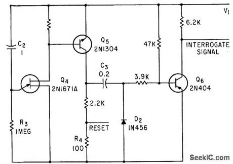
Pairs of control pulses are provided in sequence by silicon unijunction transistor in relaxation oscillator. Interval between pulses is determined by R3-C2. When C2 charges enough to trigger Q4, pulse fed to base of Q5 makes it conduct heavily; C3 charges and reset pulse is then developed across R4. Next, Q5 switches off, thereby feeding negative pulse to base of Q6 to switch Q6 off and make its collector voltage rise rapidly to form negative second pulse of pair.-C. D. Todd, Tunnel Diode Detects Currents Down to 100 Femtoamperes, Electronics, 36:14, p 33-37. (View)
View full Circuit Diagram | Comments | Reading(682)
MULTIPLE_OUTPUTS
Published:2009/7/15 23:42:00 Author:Jessie
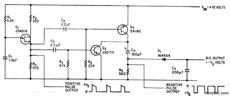
Circuit Provides negative d-c output voltage and negative output pulses, using only single d-c source .Unijuncation-transistor lator Q1 provides positive pulses, while Q2 and Q3 together invert these and drive rectifier D1 that gives -5 v at 1 ma to drive low-power amplifier that may be used in same integrated circuit.-M. H. Hussain, Circuit Inverts D-C Voltage, Electronics, 38:19, p 100. (View)
View full Circuit Diagram | Comments | Reading(810)
TUNNEL_DIODE_GIVES_FAST_MONO_RECOV
Published:2009/7/15 23:40:00 Author:Jessie

ERY-Time delay can be varied continuously over 100 to 1 range. Duty cycle is 0.9. Tunnel diode, connected between base and emitter of transistor switch, acts as current-controlled threshold detector.-P. Heffner, Tunnel Diode Multi Recovers Quickly, Electronics, 37:25, p 75-77. (View)
View full Circuit Diagram | Comments | Reading(789)
3_35_kHz_VARACTOR_TUNER
Published:2009/7/13 23:12:00 Author:May
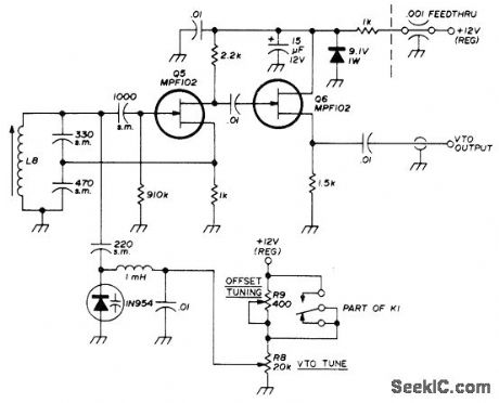
Variable oscillator for 80-meter SSB transceiver is tuned by 1N594 diode. MPFl02 FET serves as source-follower buffer, With values shown, full excursion of R8 tunes oscillator from 3.045 to 3.545 MHz. Use well-regulated 12-V source. R9 allows synchronization of receive and transmit frequencies. K1 is 4PDT relay used for switching supply voltage and antenna from transmit to receive. L8 is 40 turns No. 32 on 1/4-in slug-tuned form.-W. J. Weiser, Integrated Circuit SSB Transceiver for 80 Meters, Ham Radio, April 1976, p 48-52. (View)
View full Circuit Diagram | Comments | Reading(897)
COUNTING_AT_6_KC
Published:2009/7/13 23:12:00 Author:May
Counts pulses received, displays count. and sets carry store when necessary.-M. E. Bond, Cold-Cathode Tubes as Triggers, Electronics, 38:7, p76-85. (View)
View full Circuit Diagram | Comments | Reading(643)
4_KC_SCALER
Published:2009/7/13 23:08:00 Author:May
Drives glow tube at maximum possible rate. Uses single-shot mvbr and step-up transformer Q1 to obtain 300-V pulses required to drive glow tube. Single drive pulse is fed simultaneously to both guides of tube.-H. A, Kampf, Increasing Counting System Reliability Electronics.32:37,p112-1l3. (View)
View full Circuit Diagram | Comments | Reading(532)
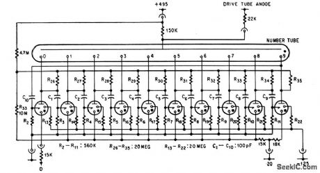
RANDOM_TIME_PULSES
Published:2009/7/15 23:39:00 Author:Jessie
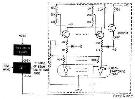
When gate is opened by noise, sine wave steps electron beam of Burroughs tube through its ten sections. Transistor connected to each target produces voltage pulse whose magnitude depends on potentiometer setting, giving sequence of different voltages in output. When beam reaches position 9, pulse is fed back to dose the gate.-C. V. Jakowatz and Q. M. White, Self-Adoptive Filter Finds Unknown Signal in Noise, Electronics, 34:7, p 117-119. (View)
View full Circuit Diagram | Comments | Reading(855)
FREE_RUNNING_CASCODE_MULTIVIBRATOR
Published:2009/7/15 23:38:00 Author:Jessie
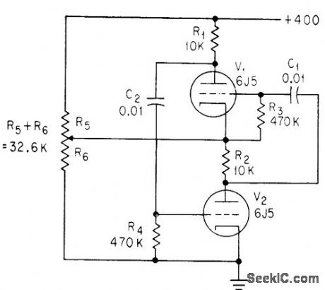
Output signal at cathode of V1 is nearly perfect square wave, either positive or negative depending on setting of potentiometer. -C. Sing, Advantages of Free-Running Cascode Multivibrators, Electronics, 37:5, p 28-29. (View)
View full Circuit Diagram | Comments | Reading(591)
LOGIC_CONTROLS_15_A_LOAD
Published:2009/7/13 23:06:00 Author:May
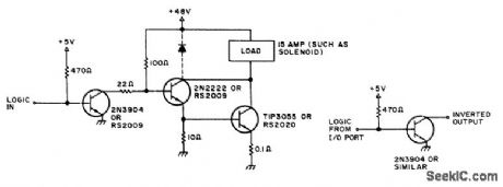
Load is energized when logic input drops to 0. Can be used to drive solenoid or electromagnet from 48-VDC supply, for stopping paper tape in high-speed tape reader. If relay is to be activated by high or 1 level, add inverter at input as shown.-D. D. Mickle, Practical Computer Projects, 73 Magazine, Jan. 1978, p 92-93.
(View)
View full Circuit Diagram | Comments | Reading(762)
HIGH_SPEED_VOX
Published:2009/7/13 23:05:00 Author:May
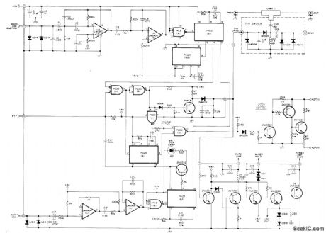
Use of switching transistors for rapid, silent voice-controlled switching of transmitter-receiver functions improves on-the-air effectiveness of SSB station. Conversation is essentially the same as when using telephone. Each set of contacts that would open or close single circuit in relay-type VOX is replaced by switching transistor. TR switch is diode-biased antenna gate in which actual switching takes place 200 μs before RF appears, being accomplished by forward-biasing diode with DC voltage. Input to LM3900 is through high-pass filter. Operation of similar solid-state VOX circuit is described in detail in earlier article by same author (see author index),-H. R. Hildreth, Syllabic VOX System for the Collins S-Line, Ham Radio, Oct. 1977, p 29-33. (View)
View full Circuit Diagram | Comments | Reading(762)
THERMAL_MONO
Published:2009/7/15 23:37:00 Author:Jessie
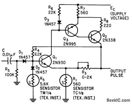
Accurate pulse periods of 15 sec to 2 minutes are produced by thermal mono using silicon resistor (Sensistor) whose resistance varies with temperature, power, and time. Used as timer to turn on plate supply 30 sec after filament supply.-L. L. Kleinberg, Sensistor Produces Long, Reliable Pulses, Electronics, 37:31, p 51-52. (View)
View full Circuit Diagram | Comments | Reading(694)
SCANNER_WITH_SEARCHBACK
Published:2009/7/13 23:03:00 Author:May
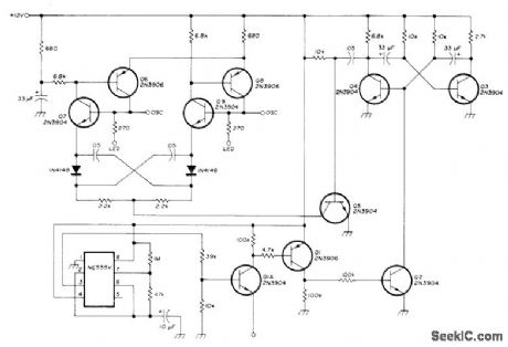
Combines scanning between two repeater channels with periodic searchback, to prevent scanner from locking on one of channels during long periods of use NE555 timer is added to squelch recognition circuit to provide automatic control of scanner so both frequencies are checked at least every 15 s,If scanner is extended to monitor four channels, none are unguarded for more than 1 min,Article shows how receiver section of transceiver is modified for diode switching by scanner of oscillator crystals for individual channels.-P, Shreve, Two-Channel Scanner for Repeater Monitoring, Ham Radio, Oct,1976, p48-51. (View)
View full Circuit Diagram | Comments | Reading(713)
| Pages:165/471 At 20161162163164165166167168169170171172173174175176177178179180Under 20 |
Circuit Categories
power supply circuit
Amplifier Circuit
Basic Circuit
LED and Light Circuit
Sensor Circuit
Signal Processing
Electrical Equipment Circuit
Control Circuit
Remote Control Circuit
A/D-D/A Converter Circuit
Audio Circuit
Measuring and Test Circuit
Communication Circuit
Computer-Related Circuit
555 Circuit
Automotive Circuit
Repairing Circuit