
Index 177
WIDE_MARK_SPACE_RATIO
Published:2009/7/16 3:49:00 Author:Jessie
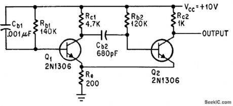
Pulse width and interpulse period are independently adjustable from tenths of microsecond to several seconds by varying Cb1-Rb1.-S. Tesic, Pulses with Variable Mark-to-Space-Ratio, Electronics, 38:14, p 78-79. (View)
View full Circuit Diagram | Comments | Reading(907)
10_40_METERS_TO_35_4_MHz
Published:2009/7/16 3:48:00 Author:Jessie
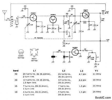
Five-band converter is designed for use with miniaturized communication receiver tuning from 3.5 to 4 MHz Signals for 80-meter band are fed directly to receiver. Two-gang tuning capacitor used to peak converter front end is film-dielectric type taken from transistor FM radio. -R. Megirian, Design Ideas for Miniature Communications Receivers, Ham Radio, April 1976, p 18-25. (View)
View full Circuit Diagram | Comments | Reading(1784)
2_AND_4_INPUT_IVOR_GATE
Published:2009/7/16 3:48:00 Author:Jessie
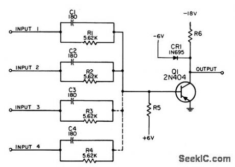
Performs general-purpose and, or, and inversion functions in compatible set of digital logic circuits for computer, control and communication equipment. Can be used as and gate for positive levels or positive-going pulses, as or gate for negative levels or negative-going pulses, and as inverter for both levels and pulses.-NBS, Handbook Preferred Circuits Navy Aeronautical Electronic Equipment, Vol. II, Semiconductor Device Circuits, PSC 7 (originally PC 210), p 7-2. (View)
View full Circuit Diagram | Comments | Reading(740)
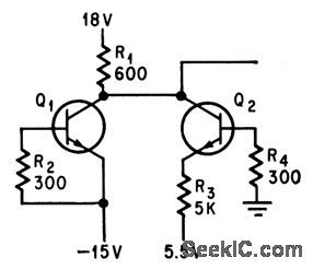
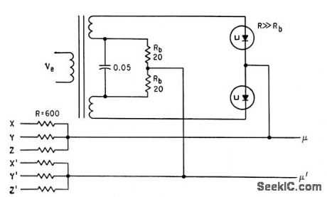
LARGEST_SIGNAL_SELECTOR
Published:2009/7/16 3:48:00 Author:Jessie
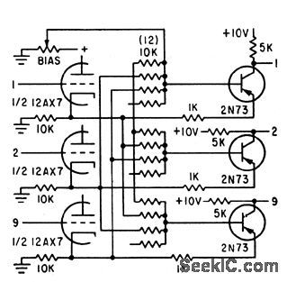
Selects single channel that has greatest amplitude, using single nor-like transistor circuit per channel-Base mixer resistance network establishes signal bias level at greatest signal level en countered in all except designated chancel-Channel transistor then conducts only when its signal at emitter is greater than all other signals.-L. R. Brown, Nonscanning Character Reader Uses Coded Wafer, Electronics, 33:48, p 115-117. (View)
View full Circuit Diagram | Comments | Reading(757)
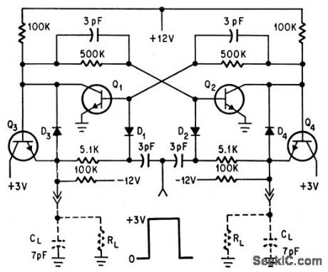
CROSS_CONNECTED_INVERTERS_AS_FLIP_FLOP
Published:2009/7/16 3:48:00 Author:Jessie
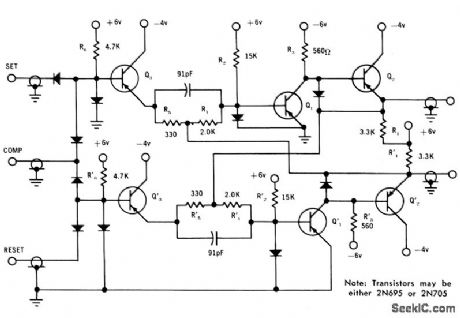
Output levels are 0 and 3.5 V. Switching times ore 20 to 34 nsec for resistive loads and 30 to 44 nsec for capacitive loads.-W. D. Roehr, For Computers...Basic RCTL Circuits, Motorola Application Note AN-129, Nov, 1965. (View)
View full Circuit Diagram | Comments | Reading(664)
CLOCK_PULSES
Published:2009/7/16 3:48:00 Author:Jessie
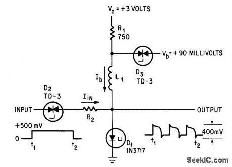
Tunnel-diode one-shot produces number of pulses in series, proportional to value of L1 and width of input pulse.-C. A. Budde, Pulse Width Converted to Pulse Sequence, Electronics, 38:4, p 86-87. (View)
View full Circuit Diagram | Comments | Reading(773)
RECEPTOR_TYPE_NEURON_MODEL
Published:2009/7/16 3:47:00 Author:Jessie
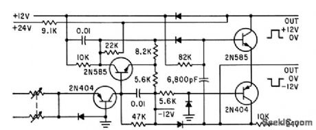
Uses integrator quench circuit. Outputs of 100 or more such neuron circuits are combined so experiments can be repeated consistently,with minimal interaction.-C. M. Wiley, Bionics on Program at Midwest's NEC, Electronics, 34:40, p 61-67. (View)
View full Circuit Diagram | Comments | Reading(715)
X_AMPLIFIER_FOR_COINCIDENT_FLUX_MEM_ORY
Published:2009/7/16 3:46:00 Author:Jessie
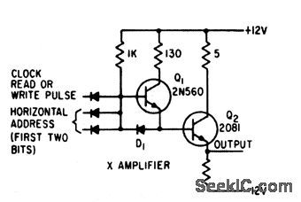
Inputs to and gate are dock read or write pulse and first two binary digits of horizontal address, forming one of the two translations for horizontal matrix of 1,120-bit memory.-H. F. Priebe, Jr., Three-Hole Cores for Coincident-Flux Memory, Electronics, 33:31, p 94-97. (View)
View full Circuit Diagram | Comments | Reading(573)
PRESSUE_CONTROLLED
Published:2009/7/16 3:46:00 Author:Jessie
Frequency of avalanche oscillator in integrated circuit using RC103 transistors varies linearly from 100 to 124 kc as stylus pressure on transistor Q2 is increased from zero to 7 grams -R. C. Wonson, Stress-Sensitive Integrated Circuits, Electronics, 38:14, p 81-84. (View)
View full Circuit Diagram | Comments | Reading(593)
MULTIPURPOSE_CHIP
Published:2009/7/16 3:45:00 Author:Jessie
Monolithic chip con sisting of six resistors and two identical transistors serves three different functions in f-m receiver. Two transistors permit cascade amplifier configuration, giving low noise fig ure and good power gain ct high frequencies.-R. L. Sanquini, Multipurpose Chips Cut Costs of F-m Receiver, Electronics, 39:10, p 80-82. (View)
View full Circuit Diagram | Comments | Reading(578)
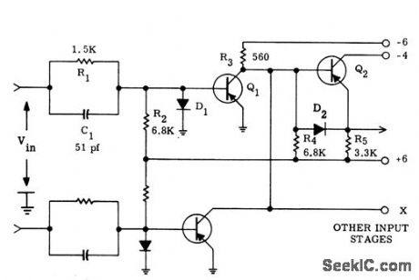
OR_GATE_FOR_DIGITAL_VOLTMETER
Published:2009/7/16 3:45:00 Author:Jessie
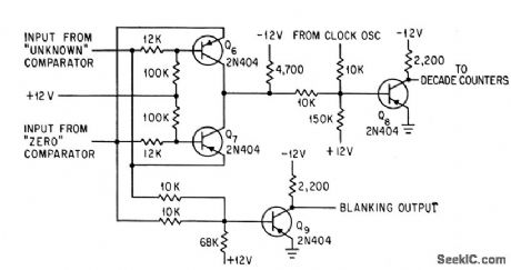
Ground-level signal output is produced only when inputs from the two comparators are in different states. Transistor Q8 gates continuously-running clock oscillator into decade counters of voltmeter.-R. C. Weinberg, Modified Ramp Generator Develops High D-C Input Impedance, Electronics, 37:8, p 33-35. (View)
View full Circuit Diagram | Comments | Reading(702)
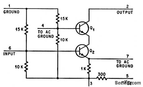
LOGIC_AND_BUFFER_AMPLIFIER
Published:2009/7/16 3:45:00 Author:Jessie
Designed to be driven by dual Schmitt trigger.-D. D. Robinson, Linear Microcircuits Scarce? Now You Con Breadboard Your Own, Electronics, 37:27, p 58-64. (View)
View full Circuit Diagram | Comments | Reading(782)
15_MC_RECEIVER
Published:2009/7/16 3:44:00 Author:Jessie
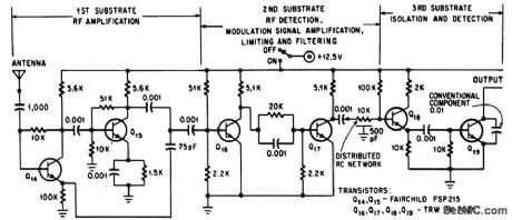
Operates 150 hours on 9 mercury cells, for applying command signals directly to brain of monkey. Thin-film pas sive components on three substrates reduce weight to 7 ounces.-W. Liben, Monkeys and Microelectronics, Electronics, 38:4, p 90-93. (View)
View full Circuit Diagram | Comments | Reading(664)
STORAGE_DIODE_SELECTION_MATRIX
Published:2009/7/16 3:44:00 Author:Jessie

Uses one diode per stored word. Four-word portion of 256-word matrix is shown. Activation of switch followed by driver drives selected diode sufficiently to permit flow of required read current. Write pulse is generated when read channel of both switch and driver are deactivated and write channel is activated.-I. Abeyta, M. M. Kaufman, and P. Lawrence, Monolithic Ferrite Memories, 1965 Fall Joint Computer Conference Preprints, Spartan Books, Washington, D. C., 1965.
(View)
View full Circuit Diagram | Comments | Reading(730)
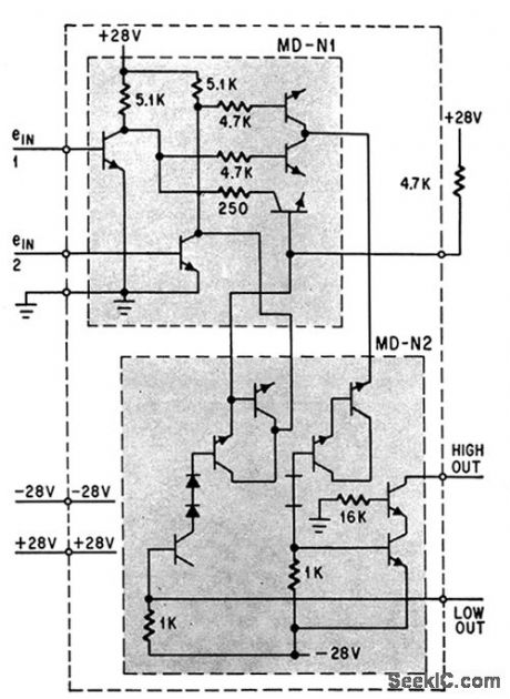
LOW_POWER_FLIP_FLOP
Published:2009/7/16 3:43:00 Author:Jessie
2N3493 micropower transistors provide rapid switching with integrated construction. Power drain is only 6.6 mw.-R. W. McGinnis and W. D. Roehr, New Masking Techniques for Micropower Transistors, Electronics, 38:4, p 76-81. (View)
View full Circuit Diagram | Comments | Reading(915)
TTL_DIGITAL_MIXER
Published:2009/7/16 3:42:00 Author:Jessie
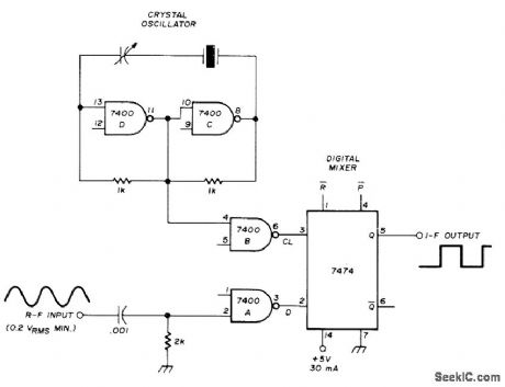
Uses two of 7400 TTL gates as crystal oscillator and other two gates as input buffers to 7474 D flip-flop serving as mixer. RF input signal must be lower than crystal frequency, and IF signal must be less than half crystal frequency. With 8-MHz crystal and 6.75-MHz RF signal, IF is 1.25 MHz. Common TTL 7474 can be used up to 25 MHz, 74H74 to 43 MHz, and 74S74 Schottky version to 100 MHz; Motorola MC12000 is good to 250 MHz.-G. H. Schrick, Introduction to the Digital Mixer, Ham Radio, Dec. 1973, p42-43. (View)
View full Circuit Diagram | Comments | Reading(3905)
LOCKED_PAIR
Published:2009/7/16 3:42:00 Author:Jessie
Ungrounded locked or Goto tunnel-diode pair permits logical inversion with no loss of speed or gain. Applications include converting analog television signals into pulse-code modulation.-C. L. Cohen, New Approach to Locked-Pair Tunnel-Diode Logic, Electronics, 35:31, p 46-47. (View)
View full Circuit Diagram | Comments | Reading(701)
THIN_FILM_AMPUFIER
Published:2009/7/16 3:42:00 Author:Jessie
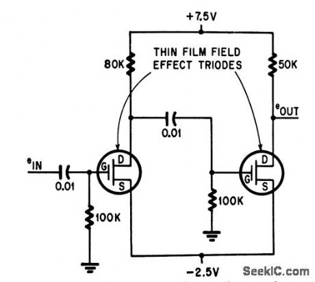
Pulse amplifier with evaporated connections uses two thin-film triodes, two silicon monoxide aluminum capacitors, and four chromium and rhenium resistors.-F. W, Schenkel, Thin-Film Capacitance Elements: Which Is Best For Your Purpose, Electronics, 38:2, p 67-72. (View)
View full Circuit Diagram | Comments | Reading(656)
SCHMITT_TRIGGER
Published:2009/7/16 3:42:00 Author:Jessie
Dual diode-coupled version for integrated construction uses eight resistors.-D. D. Robinson, Linear Microcircuits Scarce? Now You Can Breadboard Your Own, Electronics, 37:27, p 58-64. (View)
View full Circuit Diagram | Comments | Reading(0)
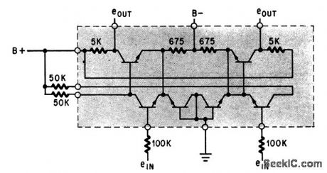
LOW_COST_INVERTER_AND_NOR_LOGIC
Published:2009/7/16 3:42:00 Author:Jessie
Inexpensive germanium pnp mesa switching transistor is used in basic inverter for high-speed computer circuits. Nor circuit is obtained by connecting other input stages to common collector load.-P. A. Mclnnis, Low-Cost Computer Circuits, Motorola Applica tion Note AN-130, Nov. 1965. (View)
View full Circuit Diagram | Comments | Reading(786)
| Pages:177/471 At 20161162163164165166167168169170171172173174175176177178179180Under 20 |
Circuit Categories
power supply circuit
Amplifier Circuit
Basic Circuit
LED and Light Circuit
Sensor Circuit
Signal Processing
Electrical Equipment Circuit
Control Circuit
Remote Control Circuit
A/D-D/A Converter Circuit
Audio Circuit
Measuring and Test Circuit
Communication Circuit
Computer-Related Circuit
555 Circuit
Automotive Circuit
Repairing Circuit