
Index 180
EXTERNAL_VOLTAGE_REFERENCE_WITH_BAR_GRAPH_DISPLAY_DRIVER
Published:2009/7/13 4:28:00 Author:May

Using external reference sources to produce (a) an adjustable 2 V and (b) up to +3V starting from +2 V. (View)
View full Circuit Diagram | Comments | Reading(842)
AUTOMATIC_TURNOFF
Published:2009/7/13 4:27:00 Author:May
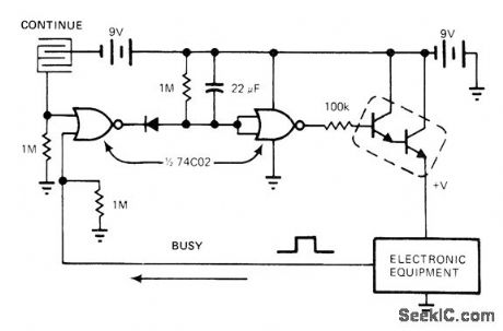
Circuit removes bias from power Darlington about 15 s after both CONTINUE and BUSY signals go low, to conserve battery life in portable electronic equipment. Intecleaved copper patterns on printedcircuit board form touch switch that must be reactivated every 15 s or kept closed by finger contact while equipment is being used.-R.D.Wood, Replace Bulky Mechanical Switches with Touch Controls, EDN Magazine, April 20, 1978, p 132-133. (View)
View full Circuit Diagram | Comments | Reading(744)
f_NUMBER_FLASHMETER
Published:2009/7/13 4:24:00 Author:May
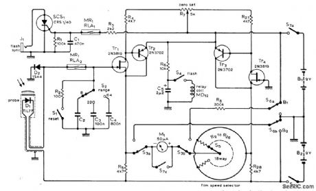
Used to measure light produced at subject position by electronic flashlamps prior to actual taking of picture.Meter is calibrated to read correct f-number setting of lens aperture. Three ranges are provided,from f/2 to f/64, while film speed selector covers films from ASA 12 to 650.Texas Instruments TIL77 photodiode is used as sensing element in probe. Article covers construction, operation, and calibration of meter in detail. Tablein article gives values for 18 resistors (one for each film speed) selected by S5. Examples are 20K for ASA 64 and 51K for ASA 25.-R. Lewis, Photographic Flashmeter, Wireless World,Aug.1974,p273-278. (View)
View full Circuit Diagram | Comments | Reading(1671)
SCR_LIGHT_DIMMER
Published:2009/7/13 4:23:00 Author:May
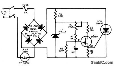
Provides full range of brightness control for up to 500w of lamps.Ujt Q1 provides turn.on pulses for scr-L.Stern, Thyristors Provide New Opportunities for Electronic Applications in the Home, Motorola Application Note AN-141, Dec.1965. (View)
View full Circuit Diagram | Comments | Reading(3339)
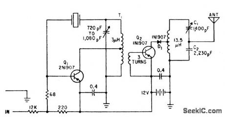
SOLID_STATE_MARKER_BEACON_RECEIVER
Published:2009/7/16 4:43:00 Author:Jessie
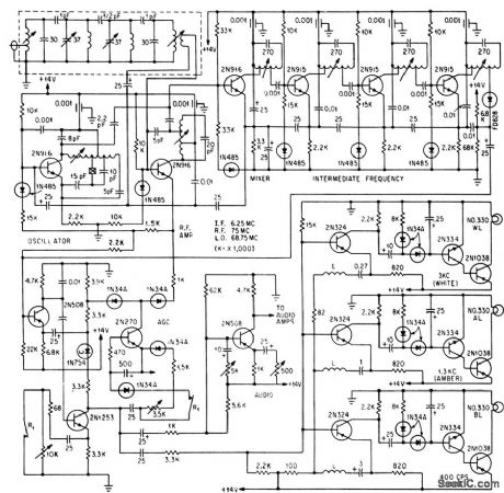
Three colored lamps glow in sequence during instrument landing system approach as 75-Mc receiver passes over three marker beacons modulated at 400, 1,300, and 3,900 cps respectively. Four-pole Butterworth filter ahead of first stage suppresses spurious response to 77.25-Mc carrier of television chanel 5. Single r-f stage isolates separate 68.75-Mc crystal controlled oscillator from antenna. Agc accomodates signals from 300 microvolts to 50 mv. -J. G. Robertson, Light-Airplane Marker-Beacon Receiver, Electronics,37:3, p 33-35. (View)
View full Circuit Diagram | Comments | Reading(1368)
CODE_COMPARATOR
Published:2009/7/16 4:45:00 Author:Jessie
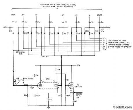
Identifies preselected code pulse train while rejecting incorrect or extraneous signals, to give distinctive marker on radar ppi when desired one of ten coded video replies is received. Thumbwheel code selection switches on beacon control box determine which code is to be recognized.-W. L. Woodson, Automatic Beacon Radar Identifies Aircraft, Electronics, 34:6, p 57-61. (View)
View full Circuit Diagram | Comments | Reading(687)
FM_TOUCH_TUNE
Published:2009/7/13 4:19:00 Author:May
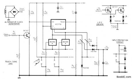
Up to 10 channels can be tuned by turning on appropriate section of 4016 CMOS digital IC by finger contact that drives clock inhibit line low. 4017B then counts clock pulses until desired output goes high. C1 and R5 ensure that channel 0 is selected when circuit is turned on. Clock frequency is not critical and can range from 100 Hz to 19 kHz. For 120-Hz clock, wind several extra turns around power transformer of receiver and feed this voltage to bridge rectifier.-L. Crampin and R. van der Molen, Touch-Tune for F.M. Receivers, Wireless World, Jan. 1978, p 60. (View)
View full Circuit Diagram | Comments | Reading(829)
10_POINT_STEPPER
Published:2009/7/13 4:19:00 Author:May

4017 divide-by-10 counter routes input clock signal sequentially to each of ten output lines, with only selected output going high. Intemal circuit of IC is self-clearing walking ring that is glitch-free, with minimum overlap between outputs. Counters can be cascaded to provide more steps. -D. Lancaster, CM0S Cookbook. Howard W. Sams, Indianapolis, IN, 1977, p 309. (View)
View full Circuit Diagram | Comments | Reading(818)
LAMTERN_BATTERY_EXTENDER_
Published:2009/7/13 4:19:00 Author:May
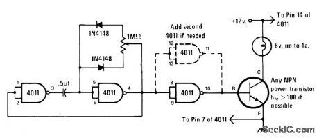
Life of lanternbattery can be tripled without reducing light by chopping current while doubling voltage at 50% duty factor. 6-V lamp is connected across chopped 12-V supply built around 4011 CMOS quad NAND gate. First two gates form chopping oscillator, while third serves as interface to any NPN high-gain power transistor. If lamp draws more than 1 A, add fourth gate as shown in dashed lines. If gate is not used, tie its input Ieads to pin 14 of IC. Duty cycle is varied with 1-megohm pot; set at midrange before ap-plying power, then adjust for normal lamp bril-liance.-J. A. Sandler, 9 Easy to Build Projects under $9, Modem Electronics, July 1978, p 53-56.
(View)
View full Circuit Diagram | Comments | Reading(836)
ADJUSTABLE_INPUT_IMPEDANCE
Published:2009/7/13 4:18:00 Author:May
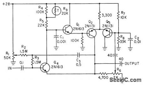
Q4, Q1, and Q2 in negative feedback loop encompass Q2 and Q3 in positive loop, to give stoble amplifier with input conductance of zero (infinite impedance) and unity gain for almost any output load, with output of l0 v p-p at 1 ma.-R. L. Willett, Positive and Negative Feedback Multiply Amplifier Input Impedance, Electronics, 34:27, p 52-53. (View)
View full Circuit Diagram | Comments | Reading(772)
ANTICOINCIDENCE
Published:2009/7/13 4:18:00 Author:May
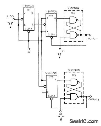
Developed for use with bidirectional counter circuits to avoid counting errors when up and down pulses occur simultaneously. Operation is based on knowing maximum frequency of separate data pulses. Outputs 1 and 2 will be separated by at least one clock period even if inputs D1 and D2 occur simultaneously. Article gives operating details. -J. H. Burkhardt, Jr., Anti-Coincidence Circuit Prevents Loss of Data, EDN|EEE Magazine, Jan. 1, 1972, p 73. (View)
View full Circuit Diagram | Comments | Reading(1970)
AM_RADIO
Published:2009/7/16 4:32:00 Author:Jessie
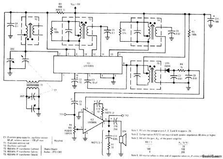
National LM1820N IC provides all sections of superheterodyne broadcast-band radio up to second detector, with diode and power opamp forming rest of receiver. Output is 1/4 W into 8-ohm loudspeaker when operating from 6-V supply. Total current drain is about 10mA, making battery operation feasible.-E. S. Papanicolaou and H. H. Mortensen. Low-Cost AM-Radio System Using LM1820 and LM386, National Semiconductor, Santa Clara, CA, 1975, LB-29. (View)
View full Circuit Diagram | Comments | Reading(0)
TOUCH_CONTROLLED_RELAY
Published:2009/7/13 4:17:00 Author:May
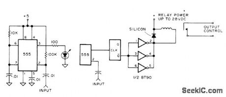
Basic circuit uses Signetics 555 timer to make LED flash each time input is touched with finger. Replace LED with flip-flop (any type) and three sections of 8T90 hex power inverter to drive DC relay. Silicon diode suppresses voltage spikes generated when magnetic field of relay collapses. Use only as many paralleled sections of inverter as are required to operate relay. Input can be brass or copper plate at least 2 inches square.-G.Young, Voltage, Current, and Power Supplies, Kilobaud, Nov. 1977, p 76-78 and 80-82. (View)
View full Circuit Diagram | Comments | Reading(1021)
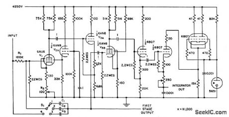
50_MICROSEC_CLEARING
Published:2009/7/16 4:29:00 Author:Jessie
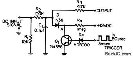
Will clear R2-C1 integrator in 50 microsec while providing isolation between integrator and switching network. Output is connected to differential amplifier for voltage level detection.-G. A. Herlich, Integrator Clearing Circuit, EEE, 14:2, p 69. (View)
View full Circuit Diagram | Comments | Reading(779)
BALLOON_TELEMETER_AND_BEACON
Published:2009/7/16 4:28:00 Author:Jessie
Delivers 10 w at 1686 kc into 72 ohms at 60% efficiency, Can also operate at 7 Mc if crystal and tank are changed.-F, W, Frykman and A. R. Moore, Lightweight Transmitter Provides Flight Data and Beacon Signal, Electronics, 34:32, p 164. (View)
View full Circuit Diagram | Comments | Reading(668)
ELECTRONICALLY_ADJUSTABLE_RESISTOR
Published:2009/7/16 4:28:00 Author:Jessie
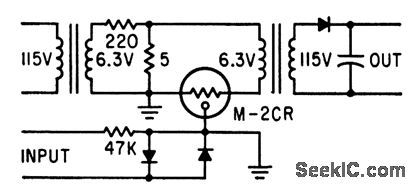
Uses Memistor in which rate of change of resistance is controlled by current applied to third electrode. Resistance range is from 2 to 30 ohms. Input pulses up to 10 V are integrated by plating action in sealed Memistor cell, to give d-c output of 0 to 3 V.-Adjustable Resistor Has Built-in Memory, Electronics, 35:51, p 76-77. (View)
View full Circuit Diagram | Comments | Reading(668)
ZERO_CROSSING_SYNCHRONIZER
Published:2009/7/13 4:14:00 Author:May
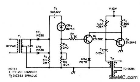
Used to synchronize firing circuit of scr's with zero crossing points of sinusoidal a-c line voltage, to initiate new timing cycle at each zero crossing and thereby permit precise control of a-c power delivered to load. In temperature control system, circuit held liquid within 0.001℃ of set point despite wide ambient temperature range.-J. D. Reed, Zero-Crossing Sync Circuit for SCR's, EEE, 12:8, p74. (View)
View full Circuit Diagram | Comments | Reading(1925)
EEPROM_DISPLAY_DRIVER
Published:2009/7/13 4:13:00 Author:May
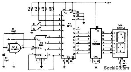
This circuit illustrates use of an EEPROM as a decoder and display driver. IC1 and IC2 generate a binary sequence of addresses in the EEPROM, and the data out of the EEPROM drive (IC4) and the display. (View)
View full Circuit Diagram | Comments | Reading(2767)
BOOTSTRAP_INTEGRATOR_AND_SWITCH
Published:2009/7/16 4:27:00 Author:Jessie
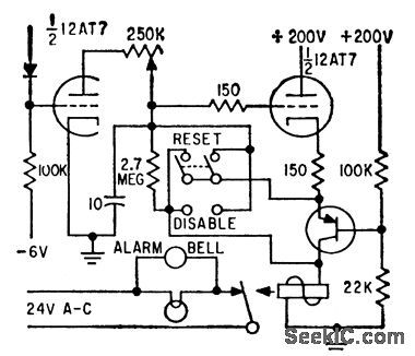


Circuit is part of memory and alarm system that accumulates predetermined numbers of pulses, then switches off until reset.-G. A. Dunn and N. C. Hekimian, Tube-Transistor Hybrids Provides Design Economy, Electronics, 32:23, p 68-70. (View)
View full Circuit Diagram | Comments | Reading(655)
CORE_FLUX_INTEGRATOR
Published:2009/7/16 4:26:00 Author:Jessie
Speeds grading and matching of magnetic cores. Miller integrator measures instantaneous and peak flux in cores at 60, 400, and 1,600 cps. Design approaches ideal response throughout 480-kc bandwidth and provides dosed-loop gain of 2 at fundamental excitation frequencies.-C. E. Goodell, Integrator-Amplifier for Core Measurements, Electronics, 31;7, p 110-113. (View)
View full Circuit Diagram | Comments | Reading(670)
| Pages:180/471 At 20161162163164165166167168169170171172173174175176177178179180Under 20 |
Circuit Categories
power supply circuit
Amplifier Circuit
Basic Circuit
LED and Light Circuit
Sensor Circuit
Signal Processing
Electrical Equipment Circuit
Control Circuit
Remote Control Circuit
A/D-D/A Converter Circuit
Audio Circuit
Measuring and Test Circuit
Communication Circuit
Computer-Related Circuit
555 Circuit
Automotive Circuit
Repairing Circuit