
Index 176
450_MC_TO_105_MC_WITH_2N2996
Published:2009/7/13 5:02:00 Author:May
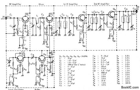


Local Colpitts oscillator operates at 345 Mc; it can deliver 5mw, but only 1 mw is required by oscillator-stabilizing buffer for good mixing action. R-f stage ahead of converter provides power gain of 13 db at noise figure of only 5.9 db.-Texas Instruments Inc. Solid-State Communications, McGraw-Hill, N.Y.1966, p305. (View)
View full Circuit Diagram | Comments | Reading(711)
LOGIC_TRIGGERED_TRIAC
Published:2009/7/13 5:02:00 Author:May
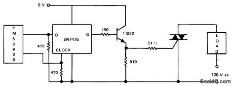
Pulsed output from microprocessor controls gate drive of triac through SN7475 clock and transistor. Pulse from one output port of microprocessor is applied to D input of clock simultaneously with pulse from communications register unit (CRU) going to clock input, to raise Q output of clock to logic 1. Output remains high until another pulse from CRU returns it to zero, thus giving latching action. High output turns on transistor and supplies about l00-mA gate drive to TlC263 25-A triac.- Thyristor Gating for μP Applications, Texas Instruments, Dallas, TX, 1977, CA-191,p4. (View)
View full Circuit Diagram | Comments | Reading(2218)
JFET_CURRENT_SINK
Published:2009/7/13 5:01:00 Author:May
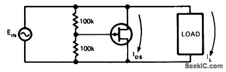
Simple circuit effectively raises load operating point of current-sen-sitive device by shunting current through JFET having nonlinear action. JFET type is not criti-cal. Applications include improvement of thyristor noise performance by diverting current around load. -V. Gregory, FET Current Sinks Raise Operating Points, EDN Magazine, Feb. 20, 1974, p 81. (View)
View full Circuit Diagram | Comments | Reading(761)
AUTO_STETHOSCOPE
Published:2009/7/13 4:57:00 Author:May
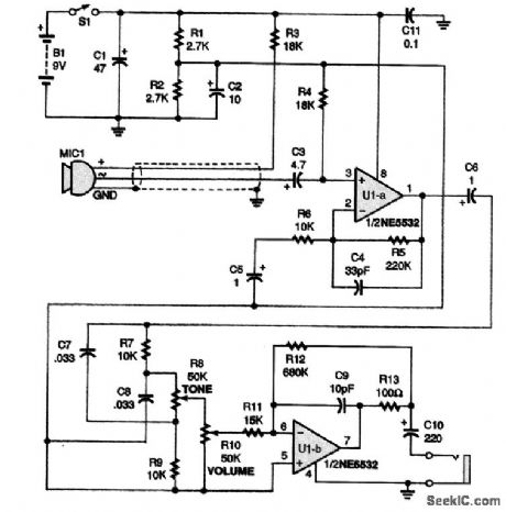
The heart of the stethoscope is the NE5532 audio op amp, U1. That component directly drives low impedances and allows the use of headphones without adding another amplifier.This circuit uses an electret microphone and an audio amplifier using a NE5532 audio op amp as an automotive diagnostic tool. The mike is mounted in a probe or piece of tubing and placed near or on various parts of the engine or other components as an aid in diagnosis; the sound generated by the suspected part is used to determine possible problems. (View)
View full Circuit Diagram | Comments | Reading(1670)
PRECISION_CURRENT_SINK
Published:2009/7/13 4:57:00 Author:May
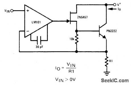
R1 serves as cur-rent-sensing resistor providing negative feed-back for opamp to enhance true current-sink nature of circuit. Both JFET and bipolar have inherently high output impedance as required for high-accuracy current sink.- FET Databook, National Semiconductor, Santa Clara, CA, 1977, p 6-26-6-36. (View)
View full Circuit Diagram | Comments | Reading(3243)
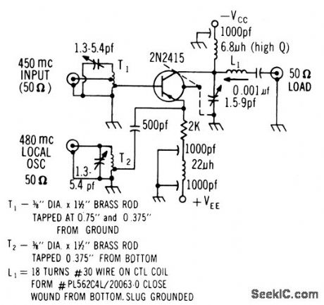
450_MC_TO_105_MC_WITH_2N2415
Published:2009/7/13 4:57:00 Author:May
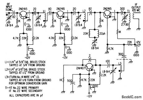
Two-stage r-f amplifier has power gain of 20 db, noise figure of 4.5 db, and bandwidth of 10 Mc, 2N1407 local oscillator operates at 345 Mc.Conversion gain of mixer is 12 db. Total antenna to i-f conversion gain is 32 db.-Texas Instruments Inc. Solid-State Communications, McGraw-Hill, N.Y.1966, p307. (View)
View full Circuit Diagram | Comments | Reading(639)
TRIAC_TRIGGER
Published:2009/7/13 4:53:00 Author:May
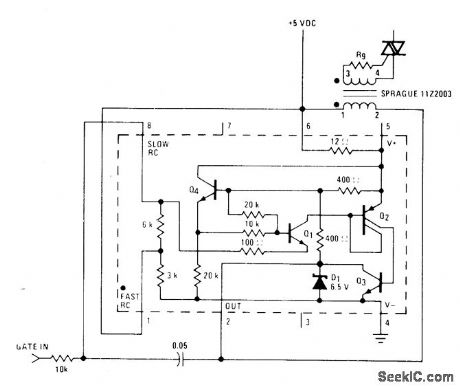
National LM3909 IC is connected as pulse-transformer driver operating from standard 5-V logic supply. IC is biased off when logic input is high. With low logic input, IC provides 10-μs pulses for transformer at about 7 kHz. Trigger is not synchronized to zero crossings but will trigger within 8 V of zero for resistive load and 115-VAC line. Triggering oc cum at about 1 V, but trigger level can be changed by using other input resistors or bias dividers.- Linear Applications, Vol. 2, Na-tional Semiconductor, Santa Clara, CA, 1976, AN-154, p 7.
(View)
View full Circuit Diagram | Comments | Reading(3341)
AUDIO_CLIPPER_FILTER
Published:2009/7/13 4:52:00 Author:May
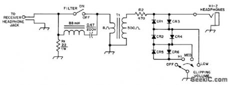
Improves seleetivity of communication receiver and prevents uncomfortablv loud volume in 500-ohm headphones. 88-mH toroid and 0.47-μF capaeitor form series resonant circuit at about 750 Hz with 6-dB bandwidth of 75 Hz. R2 and diodes form audio clipperwhose level is determined by forward conduction voltage of diodes. With ger-manium diodes for CR1-CR4 and silicon for CR5-CR6, each successive switch position boosts volume 6 dB. For low-impedance headphones, omit T1 and use 8 ohms for R2.-A, R Bloom, An Audio Clipper/Filter, QST, Aug. 1977, p 48. (View)
View full Circuit Diagram | Comments | Reading(989)
30_TO_325V_D_C
Published:2009/7/13 4:52:00 Author:May
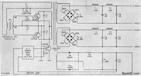
Use of transistors with high alpha cutoff frequency, along with loading networks across output bridge rectifiers,minimizes switching spikes in output. Control-loop amplifier provides overall regulation.-C. J. Biggerstaff, Reducing Spikes in D-C to D-C Converter Outputs, Electronics,34:42. p64-65. (View)
View full Circuit Diagram | Comments | Reading(815)
5_mA_WITH_VARIABLE_SLOPE_START
Published:2009/7/13 4:52:00 Author:May
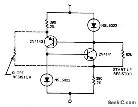
UP-Low-cost NSL5022 LED typically has 1.6-V drop at 2 mA, to produce constant 0.9 V across 390-ohm emitter resistors in circuit shown. Use of two current sources, each feeding other's LED reference, eliminates all voltage defects except for small voltage-dependent changes in transistor parameters. Adding 240K slope resistor can eels these changes, holding current constant within 0.1% over supply voltage range of 5-20 V. Applications include use as voltage divider with gain, Q multiplier for tuned circuits, and bias compensation. -P. Lefferts, Variable Slope Current Source Starts at 2.5 v, EDN Magazine, Nov. 5, 1975, p 100. (View)
View full Circuit Diagram | Comments | Reading(692)
DRIVING_240_VAC_TRIAC
Published:2009/7/13 4:51:00 Author:May

Two Motorola MOC3011 optoisolators are used in series as interface between logic and triac controlling 240-VAC load. 1-megohm resistors across optoiso-lators equalize voltage drops across them. Choice of triacdepends on load to be handled.-P.O'Neil, Applications of the MOC3011 Tridc Driver, Motorola, Phoenix, AZ, 1978, AN-780, p5.
(View)
View full Circuit Diagram | Comments | Reading(1369)
LAMP_SURGE_SUPPRESSOR
Published:2009/7/13 4:48:00 Author:May
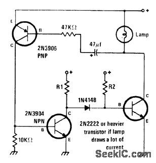
Circuit limits turn-on current through cold filament, which is major cause of lamp failure but provides normal current when filament reaches operating temperature. Developed primarily for use with lamps in locations where replacement is extremely difficult. Values shown a re primarily for low-voltage pilot lamps such as No. 44 and No.47 but can be applied to any lamp within voltage and current ratings of transistors used,-J. A.Sandier, 11 Projects under $11, Modern Electronics, June 1978, p 54-58. (View)
View full Circuit Diagram | Comments | Reading(863)
CHOPPER_FOR_IC_TESTER
Published:2009/7/16 3:51:00 Author:Jessie
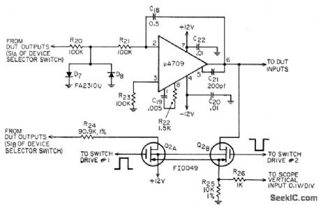
Shows circuit using Fairchild 709 IC null amplifier in feed-back loop around linear integrated-circuit tester, and FI 0049 dual mos fet serving as chopper for displaying offset voltage and transfer function simultaneously on scope by switching in synchronism with horizontal sweep.-J. N. Giles, How to Measure Linear-IC Performance, EEE, 14:8, p 62-68 and 161. (View)
View full Circuit Diagram | Comments | Reading(1759)
TRANSISTOR_DIODE_AfOR_GATE
Published:2009/7/16 3:51:00 Author:Jessie
Low leakage and low storage time of silicon epitaxial transistor allow omission of base turn-off sup ply while giving medium-speed operation over wide temperature rallge, up to 2 Mc for two cascaded logic stages.-D. Hall, Using Epitaxial Transistors in Switching and R-F Circuits, Electronics, 34:13, p 52-53. (View)
View full Circuit Diagram | Comments | Reading(807)
TWO_TRANSISTOR_CASCODE_MULTIVIBRATOR
Published:2009/7/16 3:51:00 Author:Jessie
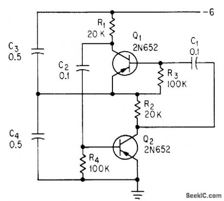
Two capacitors in voltage-divider storage circuit control transistors to give choice of rectangular or sawtooth waveforms at output of Q1, depending on time constants C1-R3 and C2-R4.-C. Sing, Advantages of Free-Running Cascode Multivibrators, Electronics, 37:5, p 28-29. (View)
View full Circuit Diagram | Comments | Reading(1013)
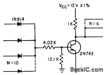
HIGH_NOISE_IMMUNITY_LOGIC
Published:2009/7/16 3:50:00 Author:Jessie
Basic gate uses zener with 5.5.V breakdown to give, high noise immunity for variety of logic circuits, at penalty of relatively high supply voltage. D1 prevents Q1 and Q2 from being on simultaneously, even during severe transients.-Higher-Voltage ICs Crack Noise Barrier, EEE, 14:8, p 40-42. (View)
View full Circuit Diagram | Comments | Reading(824)
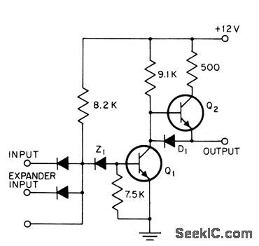
AMPLITUDE_DISCRIMINATOR
Published:2009/7/16 3:50:00 Author:Jessie

High-speed trigger with adjustable bias network and cathode-follower output serves as amplitude discriminator for tachometer that responds to pulses produced by gamma radiation sources on sealed-in rotating parts not directly coupled to input or output shafts of transmissions or turbines.-R. R. Bockemuehl and P. W. Wood, Unique Two-Channel Tachometer uses Radioisotopes, Electronics, 35:49, p 44-45. (View)
View full Circuit Diagram | Comments | Reading(1489)
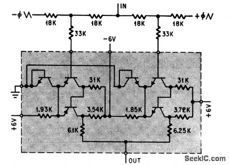
5_MC_MVBR
Published:2009/7/16 3:50:00 Author:Jessie

Constant-current generators Q1 and Q2 conduct continuously. Timing capacitor C1 charges through Q1 and Q4 and discharges in next half-period through Q2 and Q3, all in saturated states. Output pulse amplitude is 4 V at up to 5 Mc. -V. M. Ristic, Simple Multivibrator Operates at 5 Mc , Electronics, 38:17, p 86-87. (View)
View full Circuit Diagram | Comments | Reading(709)
COMPLEMENTARY_DUAL_SCHMITT_TRIGGER
Published:2009/7/16 3:50:00 Author:Jessie
Provides inverting and noninverting outputs for pulse-width modulation.-D. D. Robinson, Linear Microcircuits Scarce? Now You Can Breadboard Your Own, Electronics,37:27, p 58-64. (View)
View full Circuit Diagram | Comments | Reading(671)
100_Ws_PHOTOFLASH
Published:2009/7/13 4:45:00 Author:May
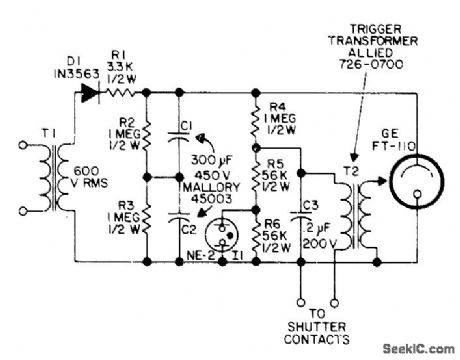
Uses AC supply and large storage capacitors to give intense flash lasting only about 250 ms, as required for stop-motion photography of fast-moving objects such as bullets. For battery-powered operation, T1 can be replaced by solid-state chopper circult. Contacts can be in camera or in external control device.-W. E. Hood, Lightning in a Bottle, 73 Magazine, Sept. 1974, p 109-112. (View)
View full Circuit Diagram | Comments | Reading(604)
| Pages:176/471 At 20161162163164165166167168169170171172173174175176177178179180Under 20 |
Circuit Categories
power supply circuit
Amplifier Circuit
Basic Circuit
LED and Light Circuit
Sensor Circuit
Signal Processing
Electrical Equipment Circuit
Control Circuit
Remote Control Circuit
A/D-D/A Converter Circuit
Audio Circuit
Measuring and Test Circuit
Communication Circuit
Computer-Related Circuit
555 Circuit
Automotive Circuit
Repairing Circuit