
Index 172
CIVIL_AIR_PATROL_CONVERTER
Published:2009/7/13 20:22:00 Author:May
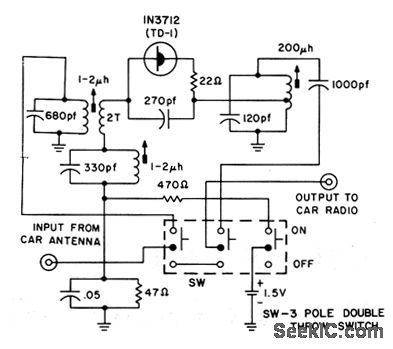
Tunnel-diode oscillator in self-oscillating converter permits reception on aviation band with auto radio.- Transistor Manual, Seventh Edition, General Electric Co.1964,p358. (View)
View full Circuit Diagram | Comments | Reading(767)
ELECTROLUMINESCENT_PANEL
Published:2009/7/13 20:20:00 Author:May

Electroluminescent (EL) panels offer a viable alternative to LED, incandescent, or CCFL backlighting systems in many portable devices. EL panels are thin, rugged, lightweight, and low power; require no diffuser, and emit aesthetically pleasing blue-green light. Capacitive in nature, they typically exhibit about 3000 pF/in2 of panel area and require a low-frequency (50 Hz to 1 kHz) 120-V rms ac drive. These problems can be solved by using a setup that includes an LT1303 micropower switching-regulator IC along with a small surface-mount transformer in a flyback topology. The 400-Hz drive signal can be supplied externally or derived from a simple CMOS 555 circuit. When the drive signal is low, flyback transformer T1 charges the panel until the voltage at point A reaches 240 Vdc. C1 removes the dc component from the panel drive, resulting in +120 Vdc at the panel. When the input drive signal goes high, the LT1303's feedback (FB) pin is pulled high as well, idling the IC and turning on Q1. Q1's collector pulls point A to ground and the panel to -120 Vdc. C2 can be added to limit voltage if the panel is disconnected or open. R1 provides intensity control by varying the output voltage. Intensity also can be modulated by varying the drive-signal frequency. (View)
View full Circuit Diagram | Comments | Reading(1006)
SINE_TO_SAWTOOTH_OR_SQUARE_WAVES
Published:2009/7/13 20:19:00 Author:May
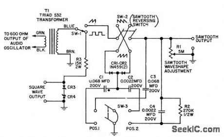
Changes 50 to 17,000 cps sine waves to either waveform, using only power of signal itself. Sawtooth is obtained from sine wave by linear charging of capacitors. Switch position 1 covers 50 to 2,000 cps, and position 21,800 to 17,000 cps. CR3 and CR4 are IRC 60-1505 zener diodes (8V-0.1V).-M. W. Raybin, Converts Sine Waves to Saw, tooth or Square Waves, EEE,10:11,p28. (View)
View full Circuit Diagram | Comments | Reading(760)
ELECTRONIC_EXPERIMENTERS_HANDBOOK
Published:2009/7/13 20:16:00 Author:May
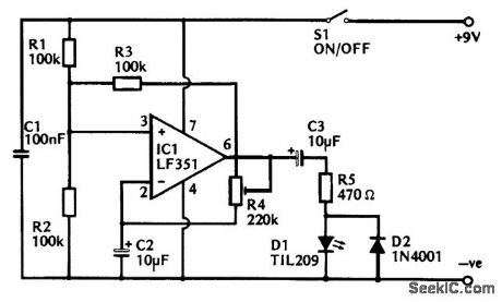
The circuit diagram for the 1-s flasher is based on an operational amplifier that is biased by R1, R2, and R3 to act as a form of Schmitt trigger. The output goes to the low state if the inverting input is taken above 2/3V+, and high if it istaken below 1/3V+. The output, therefore, goes high initially, but C2 soon charges to 2/3V+ via R4, and then the output, goes low. Capacitor C2 then discharges to 1/3V+ via R4, sending the output high again, and producing continuous oscillation. ResistorR4 is adjusted to give an operating frequency of 1 Hz. The 1-s flasher can be calibrated against a watch or clock with asecond hand by empirical means. The output of IC1 is coupled to the LED indicator, D1, by way of dc blocking capacitor C3and current-limiting resistor R5, and the LED is briefly pulsed on as the output voltage swings positive. Diode D2 ensures that there is both a charge and a discharge path for C3 so that the output signal is properly coupled to D1. The current consumption of the unit is about 2 mA. (View)
View full Circuit Diagram | Comments | Reading(876)
FREQUENCY_TO_D_C_CONVERTER
Published:2009/7/13 20:15:00 Author:May
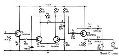
Used in place of costly frequency meter for frequency measurements from 10 cps to 1 Mc,having almost any input waveform. Overcall accuracy is 3%. Medium-power 12-v zener should be used to stabilize supply voltage.-T. Mollinga, Frequency-to-DC Converter for Lob Measurements, EEE, 12:8, p84. (View)
View full Circuit Diagram | Comments | Reading(722)
POWER_CONVERTER
Published:2009/7/13 20:12:00 Author:May

Silicon transistor version gives 15w output from 24-V supply at 70% efficiency, while germanium version gives over 100w at 90% efficiency. With germanium transistors, diode D1 and supply voltage must bereversed.-T.R.Pye, Design of Transislor Power Converters, Electronics, 32:36, p56-58; (View)
View full Circuit Diagram | Comments | Reading(1747)
FREQUENCY_TO_VOLTAGE_CONVERTER
Published:2009/7/13 20:09:00 Author:May
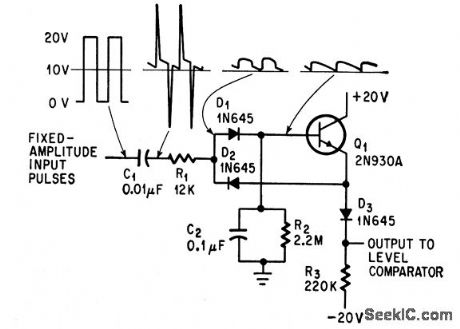
Linear staircase generator delivers d-c output voltage proportional to repetition frequency of input pulses while reiecting short-duration spurious noise pulses.-M. Merlen and D.Grossman, Interrogator Circuit Can Tell Good Data from Bad, Electronics, 37:20, p58-59. (View)
View full Circuit Diagram | Comments | Reading(2117)
COMMUNITY_TV_UP_CONVERTER
Published:2009/7/13 20:07:00 Author:May
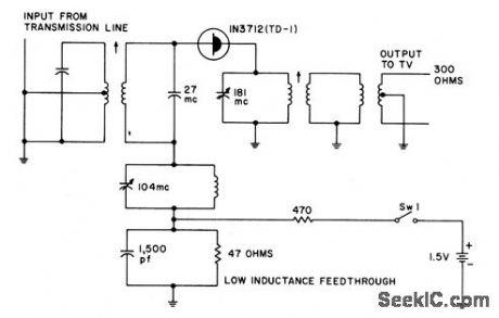
Uses tunnel-diode oscillator.- Transistor Manual. Seventh Edition,General Electric Co.1964.p359 (View)
View full Circuit Diagram | Comments | Reading(693)
CRYSTAL_CONTROLLED_CB_CONVERTER
Published:2009/7/13 20:05:00 Author:May
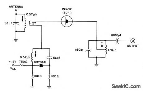
Uses tunnel-diode oscillator.- Transistor Manual, Seventh Edition,General Electric Co.1964.p358 (View)
View full Circuit Diagram | Comments | Reading(768)
AUDIO_DRIVEN_XENON_TUBE_FLASH_CIRCUIT
Published:2009/7/13 11:32:00 Author:May
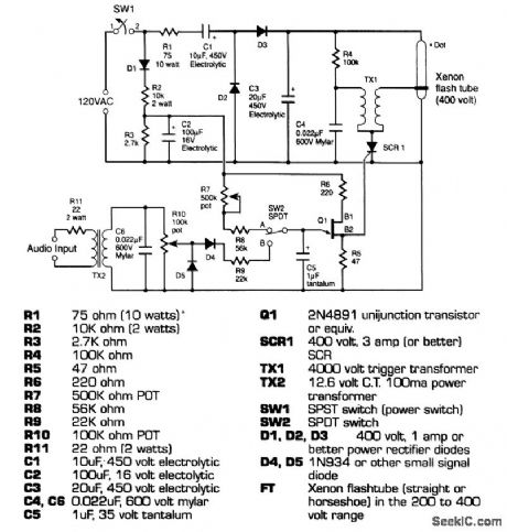
This circuit uses a Xenon flashtube to create a very real lightning effect. It can be driven in one of two ways: by sound input or by straight repeated flashes, depending on where switch 2 is positioned. When producing straight flashes, the rate is determined by pot R7. If the switch is set to be triggered by sound, the sensitivity is determined by the level of the sound driving the transformer TX2 and the setting of pot R10. This circuit uses high voltages (over 4000 V for the trigger), and extreme care should be taken by anyone that builds it. The high-voltage capacitors can hold dangerous voltages for some time (even after the circuit has been unplugged). Strong caution concerning part polarity is highly urged. (View)
View full Circuit Diagram | Comments | Reading(2001)
XENON_FLASHTUBE_CIRCUIT
Published:2009/7/13 11:14:00 Author:May
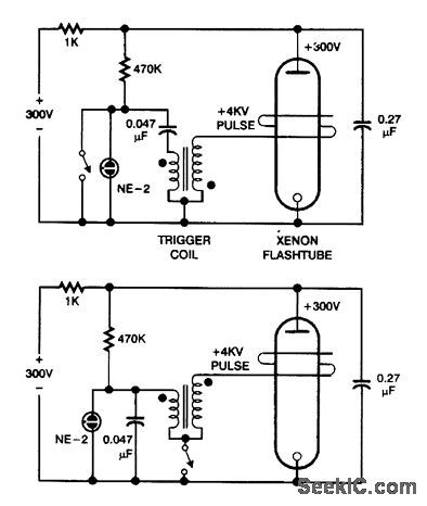
These are basic circuits for firing Xenon flashtubes. Which circuit is applicable depends on trigger coil polarity. (View)
View full Circuit Diagram | Comments | Reading(1032)
MULTIPLE_FEEDBAGK_BANDPASS_ACTIVE_FILTER
Published:2009/7/13 11:05:00 Author:May
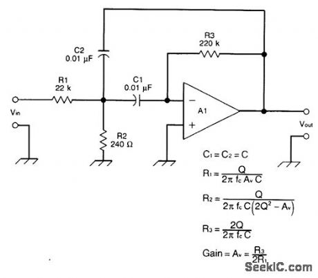
This is a multiple-feedback-path(MFP)bandpass filter. (View)
View full Circuit Diagram | Comments | Reading(1070)
TV_ON_INFRARED_BEAM
Published:2009/7/16 3:22:00 Author:Jessie
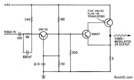
Forward-biased gallium arsenide diode converts video input signal to video-modulated infrared radiation with up to 85% efficiency.-R. H. Rediker et al., Gallium-Arsenide Diode Sends Television by Infrared Beam, Electronics, 35:40, p 44-45. (View)
View full Circuit Diagram | Comments | Reading(697)
ACTIVE_HP_FILTER_
Published:2009/7/13 11:04:00 Author:May
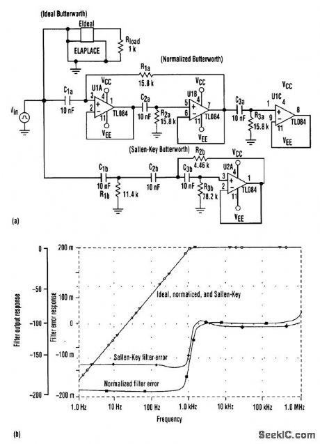
Interchanging the resistors and capacitors transforms the normalized low-pass filter into a high-pass filter with the same corner frequency (a). Notice that the Sallen-Key filter must be modified according to impedance levels at each node. This yields a filter with equal-value capacitors and unequal-value resistors, an improvement over the traditional low-pass design of equal-value resistors and unequal-value capacitors. The graphs in (b) indicate that the normalized high-pass filter compares favorably with the Sallen-Key filter in high-pass applications. (View)
View full Circuit Diagram | Comments | Reading(843)
CERAMIC_FILTER_INTERFACING
Published:2009/7/13 11:01:00 Author:May
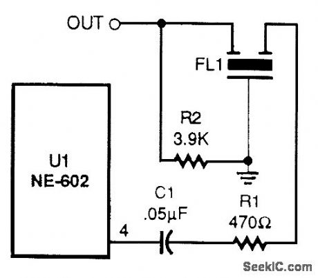
Ceramic or mechanical filters can provide a frequency-selective output. (View)
View full Circuit Diagram | Comments | Reading(667)
LOW_PASS_FILTER_PHASE_CORRECTOR
Published:2009/7/13 11:00:00 Author:May
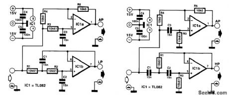
In some applications, it might be desired, or even be essential, that the bandwidth of the audio signal be limited, but that the phase relationship with the original signal be retained. A surroundsound encoder is a good example of this. The requirement can be met by combining the low-pass filter with an all-pass section and having the filtered signal compared with the signal corrected by the all-pass network. As it happens, the phase transfer of a first-order all-pass filter is exactly the same as that of a second-order critically damped network. The design of such a combination is shown in Figure 1. In this, the all-pass network is based on IC1a and the low-pass section on IC1b. The -6-dB cutoff point is at exactly 1 kHz, and the -3-dB rolloff is at 642 Hz. (View)
View full Circuit Diagram | Comments | Reading(1135)
600_TO_3000_Hz_TUNABLE_NOTCH_FILTER_CIRCUIT
Published:2009/7/13 10:54:00 Author:May
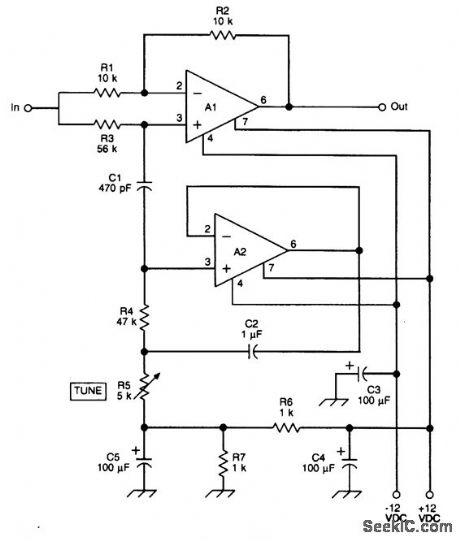
This figure shows a notch filter that will tune roughly from 600 Hz to 3 kHz; it has been used by ham and SWL builders for a number of years. It is used for notching out unwanted CW stations or for notching out heterodynes in receivqr outputs. Insert this filter between the headphone output of the receiver and a power amplifier stage. (View)
View full Circuit Diagram | Comments | Reading(858)
SUBSONIC_FILTER
Published:2009/7/13 10:52:00 Author:May
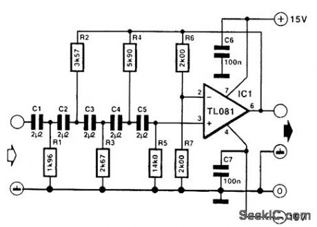
This filter is a fifth-order high-pass section that provides 1 dB attenuation at 20 Hz. Below that, however, the response drops off very steeply; the -3-dB point is at 17.3 Hz, and at 13.6 Hz, the attenuation is 10 dB. Note that it is important that C1 to C5 are within 1 percent of one another. Their individual tolerance is not so important because that merely affects the cutoff point. However, mutual deviation adversely affects the shape of the response, which should be a Butterworth characteristic as specified. All resistors are 1-percent types. (View)
View full Circuit Diagram | Comments | Reading(4980)
IF_BANDPASS_FILTER_SWITCH
Published:2009/7/13 10:31:00 Author:May
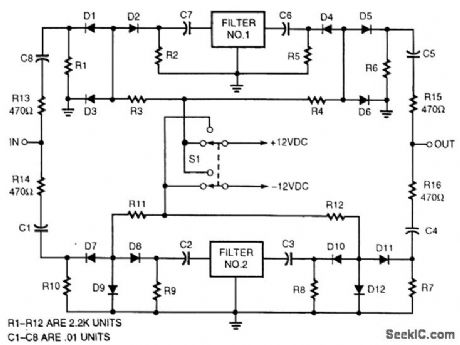
Selecting IF bandpass filters via series/shunt PIN-diode switching can be accomplished with this circuit. Diodes can be MV3404 or similar types. (View)
View full Circuit Diagram | Comments | Reading(825)
TUNNEL_DIODE_PULSE_GENERATOR
Published:2009/7/16 3:18:00 Author:Jessie
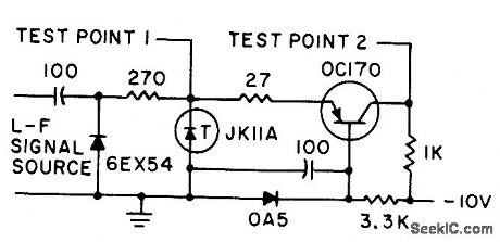
Negative-resistance characteristics of tunnel diode gives fast-rise-time rectangular pulses, in. dependently of signal frequency. Used here with common-base transistor amplifier-G. B. Smith, Tunnel Diode Generates Rectangular Pulses, Electronics, 33:48, p 124-125. (View)
View full Circuit Diagram | Comments | Reading(1055)
| Pages:172/471 At 20161162163164165166167168169170171172173174175176177178179180Under 20 |
Circuit Categories
power supply circuit
Amplifier Circuit
Basic Circuit
LED and Light Circuit
Sensor Circuit
Signal Processing
Electrical Equipment Circuit
Control Circuit
Remote Control Circuit
A/D-D/A Converter Circuit
Audio Circuit
Measuring and Test Circuit
Communication Circuit
Computer-Related Circuit
555 Circuit
Automotive Circuit
Repairing Circuit