
Basic Circuit
Index 141
50_350_MICROSEC_PHANTASTRON_DELAY
Published:2009/7/15 3:23:00 Author:Jessie
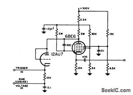
Gives 0.5% accuracy. Phantastron furnishes own gate and does not require amplifier to trigger blocking oscillator al output.-NBS, Handbook Preferred Circuits Navy Aeronautical Electronic Equipment, Vol. 1, Electron Tube Circuits, 1963, pN9-2. (View)
View full Circuit Diagram | Comments | Reading(809)
IR_REMOTE_CONTROL_TRIAC_INTERFACE
Published:2009/7/14 10:59:00 Author:May
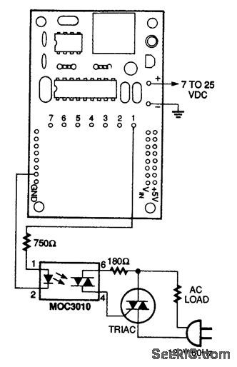
This circuit can be used to interface a triac to the IR remote control ac loads. (View)
View full Circuit Diagram | Comments | Reading(818)
PUSHBUTTON_TO_DIAL_CONVERTER
Published:2009/7/14 8:38:00 Author:May
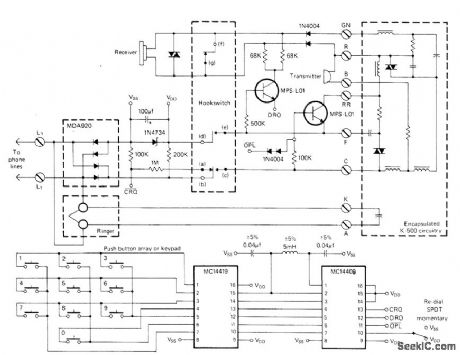
Combination of Motorola MC14419 keypad-to-binary converter and MC14408 BCD-to-dial telephone pulse convener is used with 10-switch push-button array to provide correct chain of pulses for dialing number on conventional dial-telephone system. Eleventh SPDT button is used for redial feature; if line called is busy, one press of redial button dials number over again. Number is stored for repeated use until new number is dialed. Check local telephone company regulations before making connections to telephone lines.-I. Math, A Push-Button to Dial Tele-phone Converter, CQ, Sept. 1976, p 36-37.
(View)
View full Circuit Diagram | Comments | Reading(1404)
TOUCH_TONE_BAND_REJECT_FILTER
Published:2009/7/14 8:34:00 Author:May
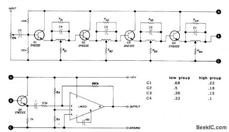
Cascaded notch filters with active limiter at output provide 20-dB attenuation of either low (697-941 Hz) or high (1209-1633 Hz) groups of tones, as aid to decoding for repeater control functions. All coils are 88-mH toroid. RA is between 5600 and 22,000 ohms, and RB is 1000 to 3000 ohms. Article gives tuning procedure for selecting resistor values and adjusting toroids so each stage rejects different tone in its band.-B. Bretz, Multi-Function FM Repeater Decoder, Ham Radio, Jan. 1973, p 24-32. (View)
View full Circuit Diagram | Comments | Reading(1393)
AUTOPATCH_RELEASE
Published:2009/7/14 8:32:00 Author:May
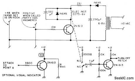
Control circuit automatically releases telephone autopatch at receiver when called party hangs up, by generating disconnect signal for patch control logic. Action is based on reversal of polarity of phone line when called party answers, and return of polarity to preanswered condition when called party hangs up. Article describes circuit operation and use.-T. R. Yocom, Automatic Auto-patch Release, 73 Magazine, April 1977, p 52. (View)
View full Circuit Diagram | Comments | Reading(2072)
TOUCH_TONE_DRIVE_FOR_LOUDSPEAKER
Published:2009/7/14 8:25:00 Author:May
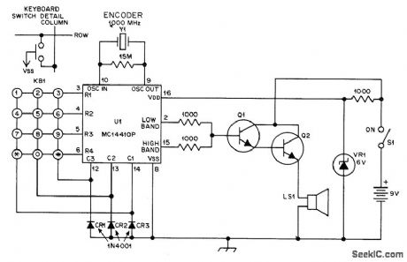
Encoder is held In front of microphone to access and use autopatch of repeater, Acoustic coupling eliminates need for opening new transceiver to make wire connections, which would void guarantee Uses Motorola MC14410P IC with KB1 keyboard (Polypaks 92CU3149). Q1 and Q2 are 2N3643 or equivalent Y1 IS 1,000 MHz crystal (Mariann Labs ML18P or Sherold Crystal HC-6) Transistors Q1 and Q2 boost out-put enough to drive 8-ohm loudspeaker Total current drain is 35 mA idling and 100 mA with full drive.-C. Gorski, A Low-Cost Touch-Tone Encoder, QST, Oct 1976, p 36-37. (View)
View full Circuit Diagram | Comments | Reading(908)
IR_REMOTE_CONTROL_RELAY_INTERFACE
Published:2009/7/14 8:23:00 Author:May
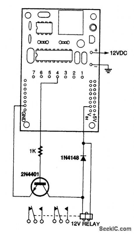
This circuit can be used to interface a relay to the IR remote control in order to control large ac or dc loads. (View)
View full Circuit Diagram | Comments | Reading(894)
IR_REMOTE_CONTROL_DC_INTERFACE
Published:2009/7/14 8:21:00 Author:May
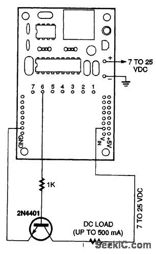
This circuit can be used to interface dc loads up to 500 mA to the IR remote control. (View)
View full Circuit Diagram | Comments | Reading(646)
TOUCH_TONE_ENCODER
Published:2009/7/14 8:19:00 Author:May
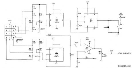
Uses 555 timers to generate Touch-Tone frequencies in pairs using two of seven possible frequencies, under control of standard 12-button pad. Adjust R10 so low-group oscillator reads 941 Hz at pin 3 of U1 when * key is pressed. Frequencies of 852, 770, and 697 Hz will then be correct within 2 % when 7, 4, and : are pressed, if 1 % resistors are used and 0.047-ptF capacitors are tantalum or Mylar, Automatic push-to-talk control uses U4 connected as 1-s mono MVBR driving relay K1.-H. M. Berlin, Homebrew Touch-Tone Encoder, Ham Radio, Aug. 1977, p 41-43. (View)
View full Circuit Diagram | Comments | Reading(935)
120_VAC_SINGLE_HETEROSTRUCTURE_LASER_DRIVER_SUPPLY
Published:2009/7/14 11:38:00 Author:May
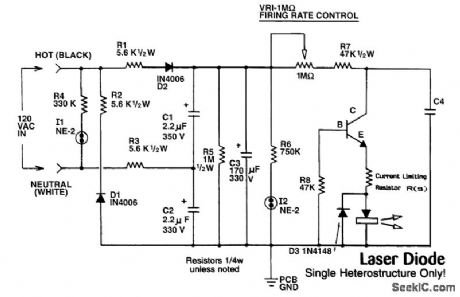
This figure shows the complete schematic of the 120-Vac SH power supply. The circuit consists of a polarized plug, a voltage doubler, a large-value storage capacitor, two neon indicator lamps to show that ac and dc power is present, a 1-MΩ firing-rate control, and the business end of the supply to drive the laser. I2 is also a safety light. When it is on, the laser should be considered operating. The current to the voltage doubler is limited by resistors R1 to R3, and by the capacitive reactance of capacitors C1 and C2. R7-a 47-kΩ, 1/2-W resistor-limits the input power to the avalanche circuit to avoid overheating the diode or Q1. The capacitors and resistors serve to isolate the circuit from the ac line sufficiently to prevent a shock hazard; however, you can still get shocked. Be sure you put this device in a nonconductive case, and obey the polarity of the polarized plug. Don't touch any part of the circuit while it's plugged in, either. Be sure you use a plastic potentiometer for VR1, or a separate control-type potentiometer with a plastic knob. (View)
View full Circuit Diagram | Comments | Reading(1145)
LASER_DIODE_DRIVER
Published:2009/7/14 11:31:00 Author:May
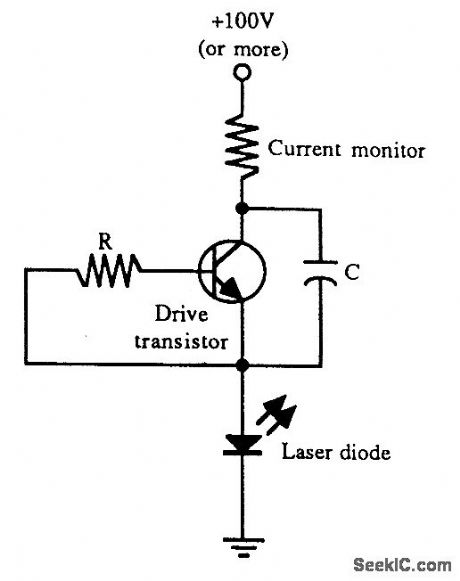
One way to drive a single heterostructure laser diode. The transistor is driven in avalanche mode, producing short-duration pulses of current. (View)
View full Circuit Diagram | Comments | Reading(1244)
D_BISTABLE
Published:2009/7/14 11:27:00 Author:May
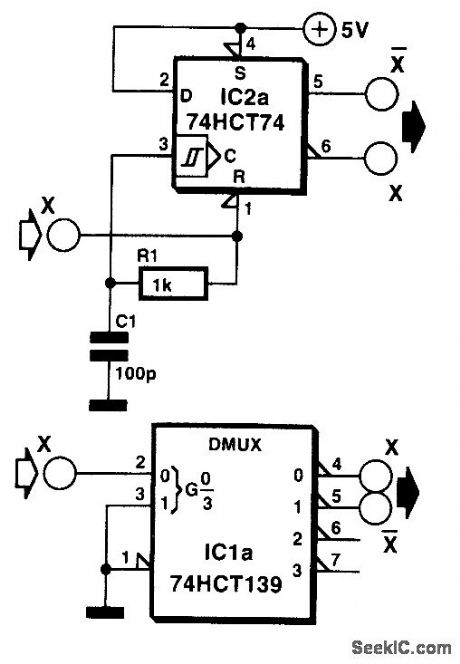
The interesting point of this circuit is that a D-type bistable is used as an inverter. When the level at the input changes from high to low, the bistable is reset and its Q output goes high. When the input becomes low, the reset is removed and the Q output goes low. The delay introduced by network R1-C1 between the RESET input and the CLOCK input makes it possible to trigger the bistable at the leading edge of the input signal. As an example, in the case of a dual D-bistable Type 74HCT74, the time needed for a clock pulse to be accepted after the reset has been removed is 5 ns. Therefore, an RC introducing a delay of 7.5 ns gives a reasonable safety margin. The reduced edge gradient of the clock pulse does not create any problems because the maximum allowed rise time of the clock input is 500 ns. To obviate asymmetrical output signals, it is advisable to limit the input frequency to about 1 MHz with component values as specified. (View)
View full Circuit Diagram | Comments | Reading(1065)
REGULATED_LOW_NOISE_VOLTAGE_INVERTER
Published:2009/7/14 11:25:00 Author:May
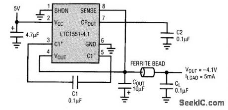
Analog cell phones rely on a quiet GaAsFET bias supply to maximize the signal-to-noise ratio, providing a high-quality transmission. The LTC 1551CS8-4. 1 switched-capacitor voltage inverter circuit shown reduces output noise to less than 1 mV on the -4.1-V regulated output voltage. The 900-kHz operating frequency allows the charge pump to use small 0.l-μF capacitors. The 10-μF and 0.1-μF output capacitors effectively reduce the 900-kHz ripple noise to relatively insignificant levels. The LTZ1550CS8-4.1 has an active low shutdown input (SHDN), whereas its counterpart, the LTC1551CS8-4.1, has an active high shutdown input. This choice minimizes component count.The LTC1550 and 1551CS8-4.1 both operate in doubler mode, meaning that they only invert the input voltage and regulate it down to -4.1 V. The input voltage range is 4.5 to 7 V. (View)
View full Circuit Diagram | Comments | Reading(745)
GATE_INVERTERS
Published:2009/7/14 11:22:00 Author:May
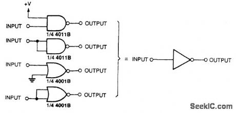
Logic gates can be configured as buffers or inverters as shown. (View)
View full Circuit Diagram | Comments | Reading(735)
CORDLESS_HEADPHONES
Published:2009/7/14 11:21:00 Author:May
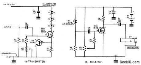
It is possible to use headphones with no direct connection to the audio source. This figure illustrates a simple transmitter circuit suitable for connecting to an audio source. Diodes D1 to D3 are three infrared LEDs in series, driven by TR2, an n-channel MOSFET with a drain-current rating of 500 mA maximum. The illumination of the LEDs is modulated by the audio signal applied, with TR1 current-limiting and shunting the bias of TR2 to ground when TR2 source current exceeds roughly 100 mA. Potentiometer VR1 should be adjusted for best results. A 9-V power supply is best used in this circuit because of the sustained level of current consumption. The transmitter range is about 1 to 2 m, but this can be extended by using reflectors behind the diodes.A suggested receiver circuit, using an infrared photodiode, D4, to detect the IR light, is shown in (b). The received signal is ac-coupled to TR3, another MOSFET. The output is taken from the drain terminal via capacitor C5. Bias can be adjusted with potentiometer VR2, and this circuit will run from a PP3-size battery. The circuit could be adapted for other applications.
(View)
View full Circuit Diagram | Comments | Reading(1776)
50_350_MICROSEC_BOOTSTRAP_DELAY
Published:2009/7/15 2:51:00 Author:Jessie

Provides continuously variable delay. Requires mvbr to generate necessary gate, and two amplifier stages following comparator diode to sharpen output waveform.-NBS, Hand-book Preferred Circuits Navy Aeronautical Electronic Equipment, Vol. 1, Electron Tube Circuits, 1963, p N9-2. (View)
View full Circuit Diagram | Comments | Reading(615)
FIXED_MVBR_DELAY
Published:2009/7/15 2:50:00 Author:Jessie
Used to provide buffer interval between sync and video information in radar relay transmitter. Can be triggered by pulse. Accuracy of 30-microsec delay is only about 10%.-NBS; Handbook Preferred Circuits Navy Aeronautical Electronic Equipment, Vol. 1, Electron Tube Circuits, 1963, p N9-1. (View)
View full Circuit Diagram | Comments | Reading(693)
INPUT_INVERTING_DELAY
Published:2009/7/15 2:49:00 Author:Jessie
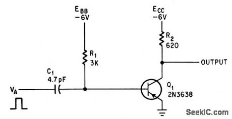
Input voltage, supply voltage EBB, and R1.C1 determine delay time for digital pulses.-R.A. Karlin, One-Transistor Multi Delays Digital Pulses, Electronics, 38:17, p 85-86. (View)
View full Circuit Diagram | Comments | Reading(763)
SLOW_BREAK_RELAY
Published:2009/7/15 2:48:00 Author:Jessie
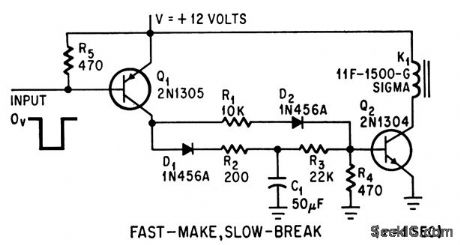
R3-C1 determine period that relay remains energized after input pulse is removed.-P. Haas, Timing Circuits Control Relays, Electronics, 38:6, p 85. (View)
View full Circuit Diagram | Comments | Reading(666)
CASSETTE_DATA_PLAYBACK
Published:2009/7/14 8:02:00 Author:May
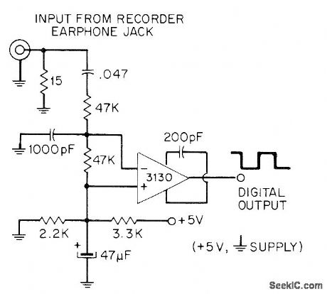
Converts low-level digital signals from cassette recorder into CMOS-compatible 5-V square waves. Both in-puts of 3130 opamp are biased to +2 V for use as open-loop comparator. RC input filter minimizes hum and bias interference.-D. Lancaster, CMOS Cookbook, Howard W. Sams, Indianapolis, IN, 1977, p 345. (View)
View full Circuit Diagram | Comments | Reading(785)
| Pages:141/471 At 20141142143144145146147148149150151152153154155156157158159160Under 20 |
Circuit Categories
power supply circuit
Amplifier Circuit
Basic Circuit
LED and Light Circuit
Sensor Circuit
Signal Processing
Electrical Equipment Circuit
Control Circuit
Remote Control Circuit
A/D-D/A Converter Circuit
Audio Circuit
Measuring and Test Circuit
Communication Circuit
Computer-Related Circuit
555 Circuit
Automotive Circuit
Repairing Circuit