
Basic Circuit
Index 145
PULSE_STRETCHER
Published:2009/7/15 3:15:00 Author:Jessie
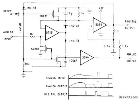
Circuit also serves as analog one-shot memory and as peak sense-and-hold with automatic reset. Digital output is logic 0 until CT and RT have decayed by onetime constant, when it goes to logic 1. Pulse duration is RCTC. Analog output amplitude is equal to input amplitude, and duration is same as digital pulse. Optical Electronics 9053 comparator automatically resets circuit after timing interval unless reset is performed manually. Analog output can be used as pulse stretcher with known and controllable pulse duration.- Analog 'One-Shot'-Pulse Stretcher, Optical Electronics, Tucson, AZ, Application Tip 10292. (View)
View full Circuit Diagram | Comments | Reading(3945)
DYNAMIC_RANGE_COMPRESSOR
Published:2009/7/15 3:15:00 Author:Jessie
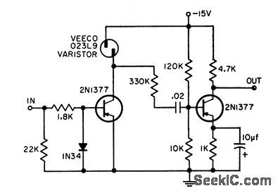
Transistorized version of vacuum-lube drawdown limiter or compressor amplifier limits dynamic range of any negative input signal without a threshold or saturation level. Output is approximately proportional to cube root of input, thus giving effective dynamic range compression. Good over audio range, yet can operate up to megacycle region if used with suitable high-frequency transistors and series inductance to varistor. Maximum input signal of 200 my produces 3 v output, corresponding to gain of 15 at maximum permissible compression.-D. E. Lancaster, Dynamic Range Compressor, EEE, 11:2, p 25. (View)
View full Circuit Diagram | Comments | Reading(2687)
SYMMETRY_CORRECTION
Published:2009/7/14 4:58:00 Author:May
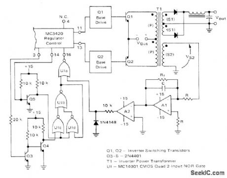
Low-cost external correction circuit for MC3420 switching-mode regulator ensures balanced operation of power transformer in push-pull inverter configuration. Circuit senses voltage impressed on primary of T1 through sensing secondary S2, for integration by opamp A1 so voltage on C represents volt-second product applied to T1. During conduction period of Q1, voltage on C ramps up to some positive value and output of A2 is low. Conduction period for output 2 then begins, Q2 turns on, and C ramps down to 0 V. A2 output then goes high, inhibiting output 2 and Q2. Times for Q2 to charge and discharge are equal so conduction periods are equal-H. Wurzburg, A Symmetry Correcting Circuit for Use with the MC3420, Motorola, Phoenix, AZ, 1977, EB-66. (View)
View full Circuit Diagram | Comments | Reading(844)
COSINE_SINE_GENERATOR
Published:2009/7/15 3:14:00 Author:Jessie
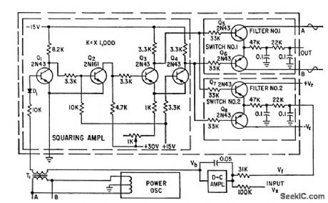
Based on fact that area under sine curve varies as cosine function. Input voltage is converted into pulse width that controls electronic switch to cut off one portion of sine wave. Resulting rectangular pulses are symmetrical with respect to positive peak of sine wave.-H. Schmid, Function Generator for Sines or Cosines, Electronics, 32:4, p 48-50. (View)
View full Circuit Diagram | Comments | Reading(887)
POLARITY_REVERSING_DRIVE
Published:2009/7/14 4:57:00 Author:May
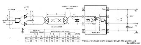
Half of 9614 polarity-reversing line driver feeds Hewlett-Packard HCPL-2602 optically coupled line receiver through shielded、twisted-pair、or coax cable. Data rate is improved considerably by using Schottky diode at input of receiver. Best data rates are achieved when tPHL (propagation delay time to low output level) and tPLH (propagation delay time to high output level) are closest to being equal,- Optoelectronics Designer's Catalog 1977, Hewlett-Packard, Palo Alto, GA, 1977、p 158-159. (View)
View full Circuit Diagram | Comments | Reading(809)
28_V_AT_100_W
Published:2009/7/14 4:56:00 Author:May
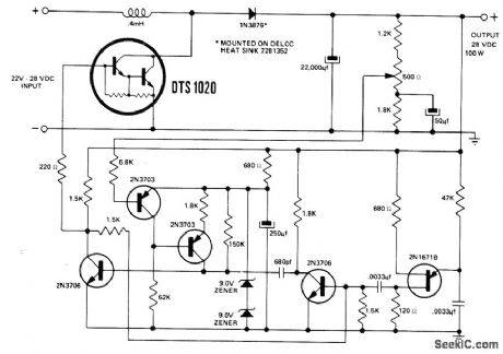
Circuit using Delco DTS-1020 Darlington silicon power transistor operates over input range of 22-28 V. Switching rate is 9 kHz. Efficiency is about 85% at full load. Out-put voltage is sensed to control pulse width of mono MVBR which is triggered at 9 kHz by os-cillator.- 28 Volt Darlington Switching Regulator, Delco, Kokomo, IN, 1971, Application Note 49, p 4. (View)
View full Circuit Diagram | Comments | Reading(730)
THEREMIN
Published:2009/7/14 4:56:00 Author:May
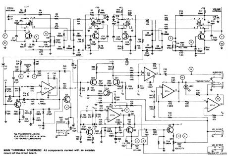
The theremin uses several RF oscillators connected to antennas to both generate audio frequencies and vary the volume of the note produced. The pitch is generated by heterodyning two oscillators, one fixed and one variable, and the volume is controlled by another pair of oscillators in which the beat frequency that is generated is used to derive a control voltage for the volume-control circuit. (View)
View full Circuit Diagram | Comments | Reading(0)
THEREMIN_CIRCUIT_VOLUME_SECTION
Published:2009/7/14 5:08:00 Author:May
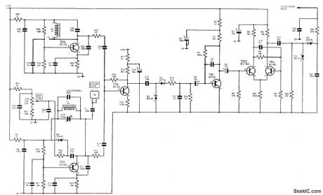
The player's hand capacitance loads down the RF to a detector stage, reducing the detector output. This output is used to control the gain of an audio amplifier in the pitch section. (View)
View full Circuit Diagram | Comments | Reading(1036)
DIGITAL_RECORDING_WITH_CASSETTES
Published:2009/7/14 5:08:00 Author:May
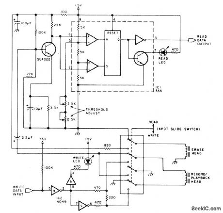
Circuit shows modifications required for standard cassette recorder to bring read level up to about 1 V. Recorder works well over range of 100 to 1200 b/s. During write process, direct current is passed through record head to saturate tape, with polarity depending on direction of current. During read cycle, voltage is induced in head winding only when transition between oppositely polarized zones moves past head. 555 timer is used as combination level detector and flip-flop to recover serial data.-R. W Burhans, A simpler Digital Cassette Tape Interface, BYTF, Oct 1978, p 142-143. (View)
View full Circuit Diagram | Comments | Reading(1024)
ONE_CHIP_THEREMIN_CIRCUIT
Published:2009/7/14 5:06:00 Author:May
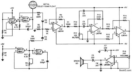
Typically, a theremin uses two separate Colpitts LC oscillators, one of which can be slightly varied in frequency. The two frequencies are mixed together, and demodulated to reveal a beat frequency. If the two oscillators are at the same frequency, there is no beat or audio, but if they are off because of the proximity of your hand, a difference or beat frequency results, which is the audio output of the theremin. A 4011 quad gate, IC1, is the heart of this theremin. Taro gates are used for each of the two required oscillators running at 250 kHz. For the aerial, use a metal toilet-tank float. It provides much better sensitivity than a length of wire. The two RF signals are mixed, then amplified by IC2, an LM741 op amp. Audio is detected by D1, a 1N34 diode. Another LM741, IC3, is set up as an adjustable bandpass filter; still another LM741, IC4, further amplifies the audio for IC5, an LM386 audio amplifier. (View)
View full Circuit Diagram | Comments | Reading(2602)
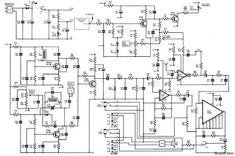
24_V_AT_3_A_FOR_CATV
Published:2009/7/14 5:06:00 Author:May
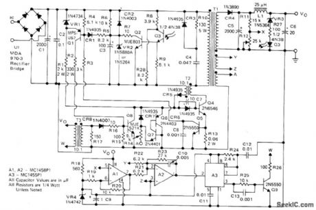
Switching regulator design meets requirements for cable television systems where small size, low weight, and high efficiency are prime considerations. Circuit operates above 18 kHz either from 40-60 V 60-Hz square-wave source (CATV power line from ferroresonant transformer) or from DC standby source. Control circuit consists of dual apamp and linear IC timer used to vary ON time of 2N6546 power transistor. At start-up, Q4 is saturated and full input voltage is applied to primary of power transformer T1. Current then ramps up linearly until 04 is switched off by opamps Al and A2 and timer A3. Power transistor is operated between saturation and OFF state at above 18 kHz, with ON time varied while OFF time is fixed, to maintain constant output voltage as sensed by Al.-J. Nappe and N. Wellenstein, An 80-Watt Switching Regulator for CATV and Industrial Applications, Motorola, Phoenix, AZ, 1975, AN-752, p 5.
(View)
View full Circuit Diagram | Comments | Reading(1456)
AUTO_GENERATOR_REGULATOR
Published:2009/7/14 5:05:00 Author:May
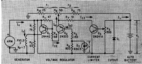
Limits maximum generator current to safe value, pre vents current flow from battery through generator when generator voltage falls below battery voltage, and regulates voltage.-L. D. Clements, Solid-State Generator Regulator for Autos, Electronics, 33;8, p 52-54. (View)
View full Circuit Diagram | Comments | Reading(2793)
THEREMIN_CIRCUIT
Published:2009/7/14 5:01:00 Author:May
A theremin produces audio derived from mixing two high-frequency oscillators and using their audio-frequency difference as the note produced. Another oscillator is used to derive a volume-control signal, which varies the audio output level. Two or more oscillators are connected to short external rod or plate antenna electrodes; these are used as controls by bringing an object (one's hands) in proximity to them. By controlling hand movements, it is possible to create music or other sounds with this device.
(View)
View full Circuit Diagram | Comments | Reading(2473)
DIGITALLΥ__PROGRAMMED_INPUTS_AND_GAINS
Published:2009/7/14 4:59:00 Author:May
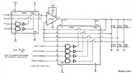
DG200 CMOS analog switch gives programmable choice of two inputs to opamp, and DG201 switch gives choice of four different gain values (1, 10, 100, or 1000) for opamp. Full opamp output range of ±12 V is provided even for unity-gain position of switch.-″Analog Switches and Their Applications,″ Siliconix, Santa Clara,CA,1976,p7-67. (View)
View full Circuit Diagram | Comments | Reading(654)
250_V_AT_3_A
Published:2009/7/14 4:52:00 Author:May
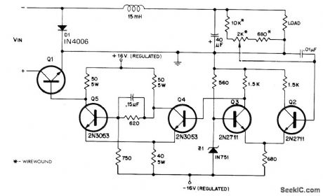
Single high-voltage silicon power transistor al serves as series element in switching regulator, with regulation obtained by pulse-width modulation. Delco DTS-431 pro-vides output of 250 V for maximum input of 325 V; other Delco transistors in same series give different combinations of output voltage and current in range of 300-750 W maximum output power. Efficiency is 92% at full load. Differential amplifier Q2-Q3 senses output voltage of regulator and feeds Schmitt trigger Q4-Q5 for turning series transistor al on and off. Resulting square wave of voltage is smoothed by LC filter between Q1 and load.- Pulse Width Modulated Switching Regulator, Delco, Kokomo, IN, 1972, Application Note 39, p 3. (View)
View full Circuit Diagram | Comments | Reading(746)
MODEM
Published:2009/7/14 4:51:00 Author:May
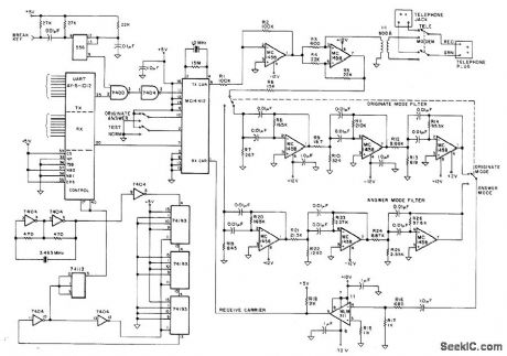
Developed as part of TV terminal for microprocessor, to permit communication over telephone line with time-sharing computer system. Uses Motorola MC14412 modem chip for full-duplex FSK modulation having originate frequencies of 1270 Hz for mark and 1070 Hz for space, with answer frequencies of 2225 Ha for mark and 2025 Hz for space. AY-5-1012 UART serves as parallel interface to microprocessor. Article covers operation, construction, testing, connection to telephone lines, and use of modem. -R. Lange, Build the S35 Modem, Kil-obaud, Nov. 1977, p 94-96. (View)
View full Circuit Diagram | Comments | Reading(1974)
SOLID_STATE_TESLA_COIL
Published:2009/7/14 4:51:00 Author:May
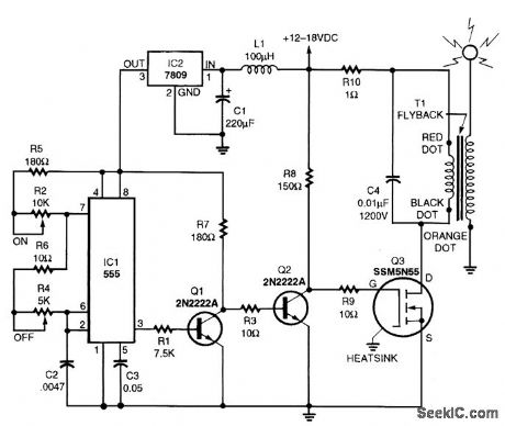
A TV flyback transformer can double as a low-power Tesla coil. The Tesla circuit consists of a pulse generator, a driver circuit, and a high-voltage transformer. Resistors R1 and R2 determine the time duration that the output at pin 3 is off, while R3 and R4 along with R1 and R2 determine the ON time. Inductor L1 and regulator IC2 provide a clean, stable power source for the timer. Transistor Q1 acts as a buffer. Resistor R6 determines the rise time based on the time constant developed by R6 and the inherent gate capacitance of Q3. Resistor R8 limits current so that excessive current will not damage T1's primary winding. Capacitor C5 absorbs some of the back EMF generated in T1's primary.The pulse waveform from IC1 is applied to Q1, which provides the high current necessary to offset the high capacitance of Q3. Capacitor C5 partially absorbs the primary EMF, reducing the stress on Q3. The spike produced in the secondary creates a ringing oscillation. When this oscillation begins to decay, Q3 is once again switched into its ON state. This dumps the energy into C5 and builds the magnetic field in T1. If the timing of both the ON and OFF states of the pulse train is adjusted correctly, the secondary of T1 produces a nearly constant, high-frequency, high-voltage current. (View)
View full Circuit Diagram | Comments | Reading(13497)
24_V_3_A_SWITCHING_MODE
Published:2009/7/14 4:50:00 Author:May
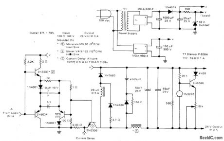
Circuit operates at 20 kHz from AC line with 70% efficiency. Control portion uses quad comparator and optoisolator and provides short-circuit protection. Logic drive uses push-pull transistors to switch 2N6306 power transistor at 20-kHz rate. Load regulation is 0.8% over output range of 1.5 to 3 A with 120-VAC input. Line regulation is 3% at 3 A for input range of 100 to 140 VAC.-R. J. Haver, “A New Approach to Switching Regulators.” Motorola, Phoenix, AZ, 1975, AN-719, p 11. (View)
View full Circuit Diagram | Comments | Reading(869)
TESLA_COIL
Published:2009/7/14 4:47:00 Author:May
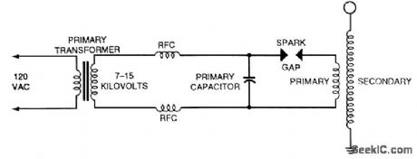
The traditional Tesla coil is connected as shown. The primary capacitor, an HV ac type, typically 500 to 5000 pF, and the inductance of the primary winding should resonate around the resonant frequency of the secondary coil. (View)
View full Circuit Diagram | Comments | Reading(0)
MULTIPLE_OUTPUT_SWITCHING_REGULA_TOR
Published:2009/7/14 4:45:00 Author:May
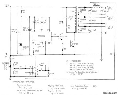
Additional output are obtained from switching regulator by adding secondary windings to power transformer. Motorola MC3380 astable MVBR serves as control element. Feedback is achieved by amplifying output error with opamp A1 and applying this voltage to pin 6. Report covers design of transformer and power circuit.-H. Wurzburg, Control Your Switching Regulator with the MC3380 Astable Multivibrator, Motorola, Phoenix, AZ, 1975, EB-52. (View)
View full Circuit Diagram | Comments | Reading(1015)
| Pages:145/471 At 20141142143144145146147148149150151152153154155156157158159160Under 20 |
Circuit Categories
power supply circuit
Amplifier Circuit
Basic Circuit
LED and Light Circuit
Sensor Circuit
Signal Processing
Electrical Equipment Circuit
Control Circuit
Remote Control Circuit
A/D-D/A Converter Circuit
Audio Circuit
Measuring and Test Circuit
Communication Circuit
Computer-Related Circuit
555 Circuit
Automotive Circuit
Repairing Circuit