
Basic Circuit
Index 150
TWISTED_PAIR___TERMINATIONS
Published:2009/7/15 4:44:00 Author:Jessie
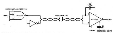
National DS7830 line driver applies digital data to twisted-Pair transmission line in high-noise environment, and DS7820 line receiver responds to data signals at other end of line while providing immunity to noise spikes. Exact value of C1 depends on line length. Supply voltage is 4.5 to 5 V for both receiver and driver, C2 is optional and controls response time. - Interface Integrated Circuits, National Semiconductor, Santa Clara, CA, 1975, p8-1-8-16. (View)
View full Circuit Diagram | Comments | Reading(1625)
HIGH_SPEED_PULSES
Published:2009/7/15 4:44:00 Author:Jessie
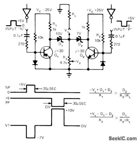
TTL circuit provides dual-polarity microsecond pulses. Pulse amplitude is adjusted by changing zeners D1, D2, or R3. Design overcomes slew-rate problems associated with most opamps.-L. Johnson, Dual-Polarity Pulses from TTL Logic, EDN Magazine, April 20, 1974, p 91.
(View)
View full Circuit Diagram | Comments | Reading(796)
_12_V_AND__15_V_FROM_5_V
Published:2009/7/14 4:07:00 Author:May
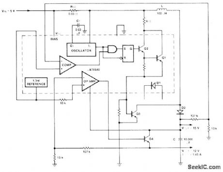
Uses Fairchild μA78S40 switching regulator having variety of internal functions that can provide differing voltage step-up, step-down, and inverter modes by appropriately connecting external components. External NPN transistor Q3 boosts step-up regulator, and NPN transistor Q4 increases series-pass regulator output well above 1 A. Total of 1.5 A is available from two outputs. Transistor and diode types are not critical. Efficiency is 80% for 15-V output and 64% for :2-V output.-R. J. Apfel and D. B. Jones, Universal Switching Regulator Diversifies Power Subsystem Applications, Computer Design, March 1978, p 103-112. (View)
View full Circuit Diagram | Comments | Reading(600)
PLL_FOR_001_Hz_TO_100_kHz
Published:2009/7/15 4:43:00 Author:Jessie
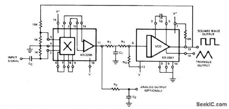
Highly stable and precise phase-locked loop system using Exar XR-2207 VCO and XR-2208 operational multiplier is suitable for wide range of applications in data transmission and signal conditioning. Supply voltage range is 16 V to ±13 V. For 10-kHz center frequency, Rois 10K and Co is 0.01μF. R1 and C1 which determine tracking range and low-pass filter characteristics, are 45K and 0.032μF,- Phase-Locked Loop Data Book, Exar Integrated Systems, Sunnyvale, CA, 1978, p 62-64. (View)
View full Circuit Diagram | Comments | Reading(1033)
LOW_PASS_FILTER
Published:2009/7/14 4:07:00 Author:May
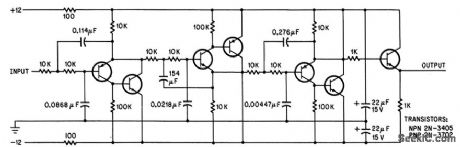
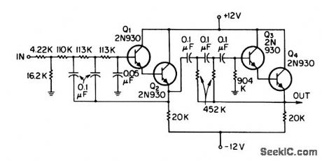
Unwanted short pulses from shot noise in celestial guidance photo-multiplier are removed by active Low-pass filter having constant phase shift over pass band. Active filter avoids bulky inductors and impedance-matching problems. Filter is modified 6th-order Bessel type, coiled a Paynter filter.-R. L. Lillestrand, J. E. Carroll, and J. S. Newcomb, Automatic Celestial Guidance, Part 2: New Challenge to Designers' Ingenuity, Electronics, 39:7, p 94-105. (View)
View full Circuit Diagram | Comments | Reading(0)
7_CPS_ACTIVE_BANDPASS
Published:2009/7/14 4:07:00 Author:May
Band width is 1.6 cps for center frequency of 7 cps.-T. Mollinga, Active Bandpass Filers, EEE, 14:8, p 115-119. (View)
View full Circuit Diagram | Comments | Reading(795)
ATV_CALL_GENERATOR
Published:2009/7/15 4:41:00 Author:Jessie
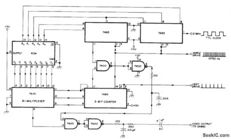
Uses 32×SPROM togenerate up to six characters of amateur call Squares in matrix are numbered 1-32 horizontally and 1-8 vertically starting from upper left. and black squares forming call letters are programmed as 1s in PROM Pin connections shown for PROM are valid for AMI 27508/27509,82S23/82S123,MM5330/MM5331、HPROM 8256、and IM5600/5610. Two 7493 binary counters address all 32 words in ROM, with clock rate (2-3 MHz) determining length of characters on screen. 74151 multiplexer advances to next ROM output once per scan Line, under control of 7493 3-bit counter clocked by horizontal drive pulses from sync generator of ATV transmitter. Positive-going horizontal drive pulses reset 5-bit word counters, while positive-going vertical drive pulses reset 3-bit line counters, to make characters appear in same position on screen for all fields.-J. Pulice, Amateur Television Callsign Generator, Ham Padio, Feb. 1977, p 34-35.
(View)
View full Circuit Diagram | Comments | Reading(790)
BEAM_SWITCHING_DECADE
Published:2009/7/14 4:06:00 Author:May
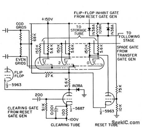
Counter is cleared when reset tube cuts off series triode in cathode of beam-switching tube. Circuit presents high impedance to initiating gate, as required for resetting several decades.-R. W. Wolfe, Decade Decimal Counter Speeds Printed Read.out, Electronics, 31:3, p 88-90. (View)
View full Circuit Diagram | Comments | Reading(747)
900_kHz_TO_10_MHz
Published:2009/7/15 4:41:00 Author:Jessie

Pulse width is variable from about 50 ns to over 500 ms by adjusting only two components. Uses VCO portion of Signetics NE562 as pulse generator and 74121 mono MVBR to ad just pulse width. Variable capacitors C3 and C6 are broadcast-band type. VCO will operate to 30 MHz, limiting factor being stray capacitance and minimum of tuning capacitor. Low-frequency limit of VCO is about 1 Hz, obtained when C3 is 300 μF.-A. Plavcan, Pulses Galore! , 73 Magazine, Jan. 1978, p 194-195. (View)
View full Circuit Diagram | Comments | Reading(1720)
800_CPS_ACTIVE_BANDPASS
Published:2009/7/14 4:06:00 Author:May
Provides bandwidth of 13 cps. Maximum gain is 24 db, and divider at input reduces this to 0 db. Selectivity at 3-db points is 72 db/octave.-T. Mollinga, Active Bandpass Fillers, EEE,14:8, p 115-119. (View)
View full Circuit Diagram | Comments | Reading(779)
10_V_SWITCHING_AT_100_mA
Published:2009/7/14 4:05:00 Author:May
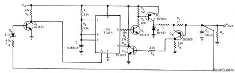
Use of 555 timer as pulse-width-modulated regulator gives line regulation of 0.5% and load regulation of 1%. Circuit includes current foldback, With 15-V input, output is 10 V, -P. R. K. Chetty, Put a 555 Timer in Your Next Switching Regulator Design, EDN Magazine, Jan, 5, 1976, p 72. (View)
View full Circuit Diagram | Comments | Reading(705)
TRIPLE_TUNED_90_OHM_OUTPUT
Published:2009/7/14 4:05:00 Author:May
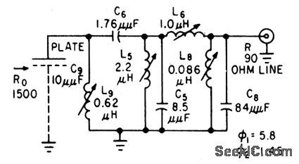
Used to provide bandpass between 55 and 65.5 Mc for signal from 10-mmfd plate capacitance.-R. B. Hirsch, How to Design Band-pass Triples, Electronics, 32:34, p 41-44. 800-cps. (View)
View full Circuit Diagram | Comments | Reading(684)
FET_VOLTAGE_CONTROLLED_RESISTOR
Published:2009/7/14 4:04:00 Author:May

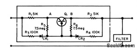
Fieldeffect transistor circuit (enclosed in dashed rectangle) serves as dropping resistor working into antiresonant a-f filter, to deliver constant voltage to filter despite input voltage variations. Uses 2N2386 fet as Q1.-H. H. Nord, the FET as a Voltage-Controlled Resistor, EEE, 13:1, p 65. (View)
View full Circuit Diagram | Comments | Reading(945)
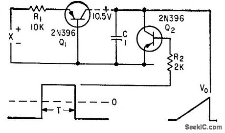
PULSE_WIDTH_MODULATOR
Published:2009/7/15 4:39:00 Author:Jessie
Combines functions of rectangular pulse generator and width modulator for analog multiplier having error less than 2% of full-scale output-A. J. Ferraro, Multiplier for Analog Computers, Electronics, 33:45, p 73-74. (View)
View full Circuit Diagram | Comments | Reading(0)
TRANSFORMER_CONTROLLED_COUNTER
Published:2009/7/14 4:04:00 Author:May
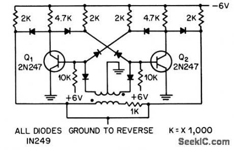
Uses conventional linear transformer in conventional bistable flip-flop to store information.-W. M. Carey, Using Inductive Control in Computer Circuits, Electronics, 32;38, p 31-33. (View)
View full Circuit Diagram | Comments | Reading(652)
ELECTRONIC_FUSE
Published:2009/7/14 4:03:00 Author:May
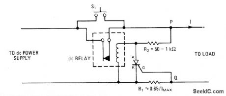
Combination of SCR and line relay gives faster action than circuit breaker for protection against current overload. Closing S1 momentarily energizes relay, completing current path from supply to load. Overload current increases voltage drop across R1 to above 0.65 v, switching on SCR and thereby shorting relay coil to make it open. S1 must be pressed again to reset relay. For adjustable dropout, gate of SCR can be connected to pot placed across R1.-R. Quong, Resettable Electronic Fuse Consists of SCR and Relay, Electronics, Sept. 15, 1977, p117. (View)
View full Circuit Diagram | Comments | Reading(2712)
ZOBEL_HIGH_PASS_FILIER
Published:2009/7/14 4:03:00 Author:May
Both examples give at least 40 db attenuation below 2,740 cps when inserted between 600-ohm source and load resistances.-K. Lichtenfeld, Method for Simplifying Filter Design, Electronics, 33:21, p 96-99. (View)
View full Circuit Diagram | Comments | Reading(1417)
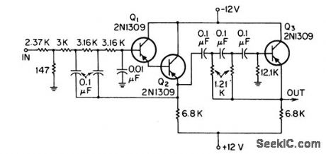
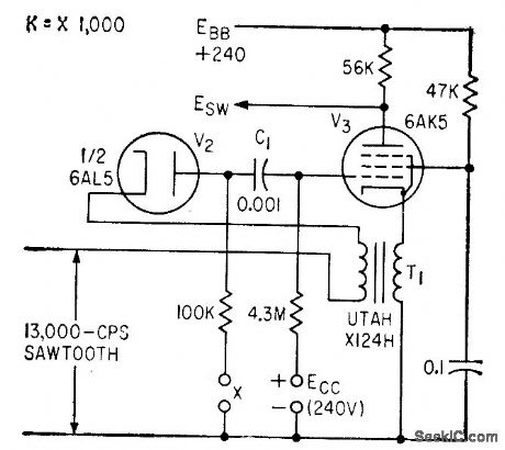
TRIANGLE_MULTIPLIER
Published:2009/7/15 4:38:00 Author:Jessie
Electronic multiplication is achieved by making slope of sawtooth wave proportional to one factor and duration to other factor. Peak height of triangle will then be proportional to product. Triangle is generated by charging C with collector current of constant generator Q1 during time interval in which Q2 is cut off. -T. R. Hoffman, Analog Multiplication Using Time as One Variable, Electronics, 33:33, p 136-138. (View)
View full Circuit Diagram | Comments | Reading(926)
BASE_GATED_BINARY
Published:2009/7/14 4:03:00 Author:May

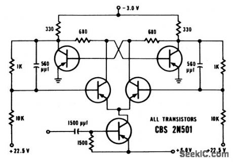
Input counting rate is up to 70 Mc. Saturating transistor gale minimizes turnoff and turnon delay. Flip-flop transition is completed in less thon 16 mil-limicrosec.-High-Speed Switching Transistors (CBS Electronics ad), Electronics, 33:39, p 45. (View)
View full Circuit Diagram | Comments | Reading(850)
50_W_RF
Published:2009/7/14 4:03:00 Author:May
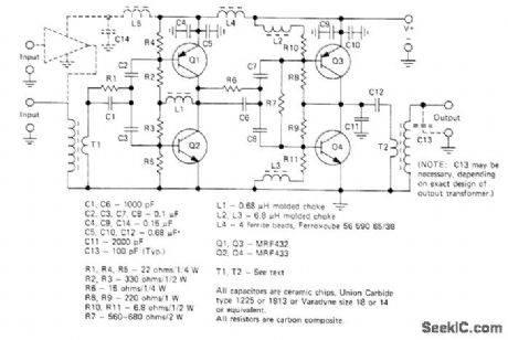
Direct-reading RF wattmeter developed for use at 27.12 MHz is accurate to within 1% of full scale. Circuit can be adapted for other frequencies up to about 100 MHz. Does not require subtraction of two readings to find power transferred to mismatched loads. RF line current and voltage are sensed by current transformer and voltage divider that can be remotely located. Meter is driven by IC balanced mixer functioning as four-quadrant analog multiplier. Average product of voltage and current appears as DC reading on microammeter.-F. C. Gabriel,Compact RF Wattmeter Measures up to 50 Watts、Electronics, Nov. 8, 1973,p 122. (View)
View full Circuit Diagram | Comments | Reading(1302)
| Pages:150/471 At 20141142143144145146147148149150151152153154155156157158159160Under 20 |
Circuit Categories
power supply circuit
Amplifier Circuit
Basic Circuit
LED and Light Circuit
Sensor Circuit
Signal Processing
Electrical Equipment Circuit
Control Circuit
Remote Control Circuit
A/D-D/A Converter Circuit
Audio Circuit
Measuring and Test Circuit
Communication Circuit
Computer-Related Circuit
555 Circuit
Automotive Circuit
Repairing Circuit