
Basic Circuit
Index 144
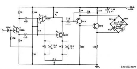
AC_MILLIVOLTMETER
Published:2009/7/15 3:22:00 Author:Jessie
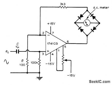
Combination of diode bridge and opamp forms basis for precise rneasurement of AC input voltages so small that they would be in nonlinear range of diodes alone Article discusses linearity problems and give output waveforms.-G, B. Clayton, Experiments with Operational Amplifiers, Wireless World, June 1973, p 275-276. (View)
View full Circuit Diagram | Comments | Reading(2364)
UJT_RELAY_OPERATING_DELAY
Published:2009/7/15 3:21:00 Author:Jessie
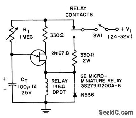
When switch is closed, capacitor charges to voltage at which uniiunction triggers, then discharges through unijunctior transistor and relay alter time delay determined by RT, which is about 1 sec of delay for each 10K of resistance.- Transistor Manual, Seventh Edition, General Electric Co., 1964, p 320. (View)
View full Circuit Diagram | Comments | Reading(1153)
MICROCOULOMETER_CONTROLLED_TIME_DELAY
Published:2009/7/15 3:20:00 Author:Jessie
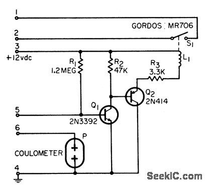
Gives delay accuracies of 1% for intervals from 30 sec to 350 hr. Delay interval ends when mercury in capillary glass tube is completely plated onto switching electrode of microcoulometer. With two delays in series, one can be reset while other is in timing mode, to give automatic reset.-Time-Delay Circuit Gives 1-Percent Accuracy, EEE, 13:9, p 94. (View)
View full Circuit Diagram | Comments | Reading(996)
HALL_EFFECT_MULTIPLIER
Published:2009/7/15 3:19:00 Author:Jessie
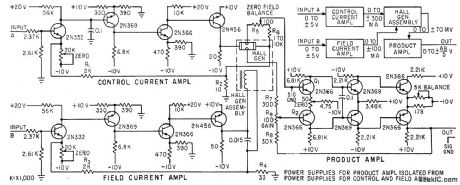
Circuit gives algebraic product of two inputs. Accuracy is only 0.5%, but cost is low. Control current is applied through long dimension of Hall semiconductor element, to produce voltage acr oss width of element that is proportional to product of control current and magnetic fluxdensity. –w. A. Scanga, A. R. Hilbinger, and C. M. Barrack, Hall-Effect Multipliers, Electronics, 33:29, p 64-67. (View)
View full Circuit Diagram | Comments | Reading(1035)
PROGRAMMABLE_0_825_Hz_PULSES
Published:2009/7/14 5:13:00 Author:May
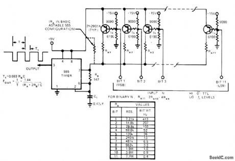
Inexpensive pulse generator is programmable in 0.4-Hz steps from 0 to 825 Hz, and can be modified to extend range to 200 kHz, Circuit uses 555 connected in astable mode, with timing resistor RA replaced by 11 sets of timing resistors and switching transistors. Inputs and outputs are TTL-compatible. When bit input is high (0), its associated transistor is turned off. When bit input is low (1), transistor is on, allowing C1 to charge. When more than one input is low, charging is through parallel combination of resistors. Width of output pulse T1 is constant over frequency range.-E. G. Laughlin, Inexpensive Pulse Generator Is Logic Programmable, EDN Magazine, Aug. 20, 1974, p 92. (View)
View full Circuit Diagram | Comments | Reading(1120)
CASSETTE_INTERFACE
Published:2009/7/14 5:12:00 Author:May
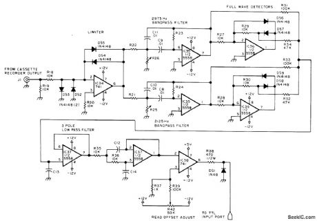
With quality recorder and tapes, interface operates reliably at 1100 bauds, for loading 24K microprocessor system in 246 s, Cassette output is amplified and clipped by limiting amplifier IC34. Bandpass filters followed by full-wave detectors respond to 2125-Hz mark and 2975-Hz space frequencies and feed their outputs to summing junction at pin 5 of three-pole active low-pass filter IC37. 2975-Hz tones are rectified to positive voltage and 2125-Hz tones to negative voltage, with amplitudes varying from maximum at exact frequencies to sum voltage of 0 V at midfrequency of 2550 Hz. Output opamp IC38 delivers correct TTL level for reading by single-bit input port.-R. Suding, Why Wait? Build a Fast Cassette Interface, BYTE, July 1976, p 46-53. (View)
View full Circuit Diagram | Comments | Reading(0)
555_AS_TONE_GENERATOR
Published:2009/7/15 3:31:00 Author:Jessie
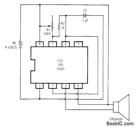
Connection of 555 timer as astable MVBR starts next timing cycle automatically, generating sequential square-wave output pulses in audio-frequency range with sufficient power to drive miniature 8-ohm loudspeaker. R1 controls frequency of tone.-F.M. Mims, Integrated Circuit Projects, Vol. 2, Radio Shack, Fort Worth, TX, 1977, 2nd Ed., p 66-70.
(View)
View full Circuit Diagram | Comments | Reading(1152)
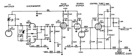
PREFERRED_30_MC_I_F_PULSE_AFC
Published:2009/7/15 3:30:00 Author:Jessie
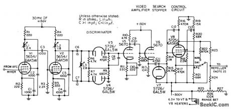
For use in pulse-modulated systems, to maintain a difference of 30 Mc between Transmitter and local oscillator frequencies. If local oscillator is required to operate 30 Mc below transmitter, discriminator diodes V3 and V4 should be reversed. Circuit is a hunting system, because local oscillator is swept over band of frequencies to find correct operating point. During search, phantastron V8 acts as saw tooth generator to provide sweep voltage for control element of local oscillator (repeller of klystron).-NBS, Handbook Preferred Circuits Navy Aeronautical Electronic Equipment, Vol. I, Electron Tube Circuits, 1963, PC 53, p 53-2. (View)
View full Circuit Diagram | Comments | Reading(660)
RING_DELAY_STARTING_UNIT
Published:2009/7/15 3:29:00 Author:Jessie
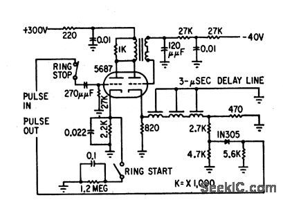
Consists of blocking oscillator and 3-microsec delay line. Ring start switch fires blocking oscillator once and starts ring. Ring stop switch opens oscillator input to slop ring delay from oscillating.-M. T. Nadir, Microsecond Sampler Handles 126 Channels, Electronics, 32:4, p 36-39. (View)
View full Circuit Diagram | Comments | Reading(745)
DIODE_PHANTASTRON_AFC_FOR_AIRBORNE_RADAR
Published:2009/7/15 3:28:00 Author:Jessie
Pentode is astable phantastron during search and d-c amplifier during lock-on.Operation is nearly independent of tube characteristics. Provides tight control of local oscillator frequency because during lock-on, pentode furnishes direct control of klystron repeller.-NBS, Handbook Preferred Circuits Navy Aeronautical Electronic Equipment, Vol.1 Electron Tube Circuits, 1963, p N 13-6. (View)
View full Circuit Diagram | Comments | Reading(766)
O_to_2440_MICROSEC_BOOTSTRAP_DELAY
Published:2009/7/15 3:28:00 Author:Jessie
Is triggered by gating mvbr. Receives control voltage from ten-turn potentiometer calibrated in distance units. Output drives blocking oscillator through transformer. Accuracy is about 1% of delay setting.-NBS, Hand-book Preferred Circuits Navy Aeronautical Electronic Equipment, Vol. 1, Electron Tube Circuits, 1963, p N9-2. (View)
View full Circuit Diagram | Comments | Reading(633)
CASSETTE_PLAYBACK_OF_CW_AND_RTTY
Published:2009/7/14 5:23:00 Author:May
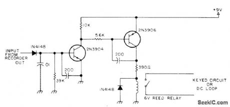
Playback-signal conditioning circuit is used between tape recorder and transmitter when routine CW calls or RTTY test messages are re-corded on endless-loop cassette recorder. Recorded tone is rectified by :N4148 and applied to RC timing circuit. Decay voltage developed across network when tone is removed turns on 2N3904 and 2N3906 stages. Output of 2N3906 drives reed relay in transmitter keying circuit. if resistor is used in place of relay, drop across it during key-down period can be used to drive electronic keyer,-Cassette-Aided CW and RTTY, 73 Magazine. Sept. 1977, p 122-123. (View)
View full Circuit Diagram | Comments | Reading(719)
CW_AND_RTTY_ON_CASSETTES
Published:2009/7/14 5:21:00 Author:May
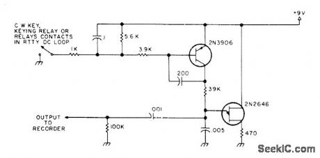
Circuit provides conditioning of routine CW calls or PTTY test messages, as required for recording on end-less-loop cassette. Keyed signal is filtered to remove contact bounce, then used to turn on 2N3906 which gates 2N2646 sawtooth oscillator operating at about 5 kHz when using 0.005-μF gate capacitor; for lower frequency, increase capacitor to 0.01μF.-Cassette-Aided CW and RTTY, 73 Magazine, Sept, 1977, p 122-123. (View)
View full Circuit Diagram | Comments | Reading(725)
COPYING_CASSETTE_PROGRAMS
Published:2009/7/14 5:19:00 Author:May
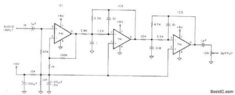
Controller serves for making duplicate copies of microprocessor programs recorded on magnetic tape, for insurance against accidental damage to master cassette during use. Used between audio out- put of cassette player and audio input of tape recorder. Opamp IC1 with gain of 100 overloads so output is constant-amplitude square wave regardless of input level from tape being copied. If program uses audio tones for digital data, eight cycles of 2400 Hz represents digital 1 and four cycles of 1200 Hz represents digital O. Additional opamps act as four-pole Butterworth filter rejecting signals above 3000 Hz. 10K pot is adjusted so output level matches requirements of recorder,-P. A. Stark, Copying Computer Cassettes, Kilobaud, Aug. 1978, p 94-96. (View)
View full Circuit Diagram | Comments | Reading(854)
RANDOM_NOISE_ANALYZER
Published:2009/7/15 3:19:00 Author:Jessie
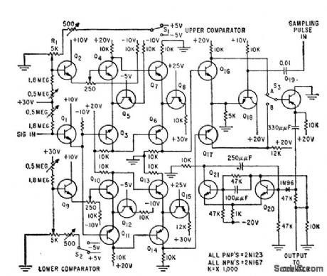


Provides digital information from which amplitude probability distribution function and probability density function can be plotted. Consists of two amplitude comparators followed by logic circuits and sampling network.-D. Hoffman and E. Schutzman, Statistical Analysis of Noise-Signal Amplitudes, Electronics, 32:30, p 48-49. (View)
View full Circuit Diagram | Comments | Reading(822)
250_W__60_CPSUAL_TRANSFORMER_IN_VERTER
Published:2009/7/15 3:18:00 Author:Jessie
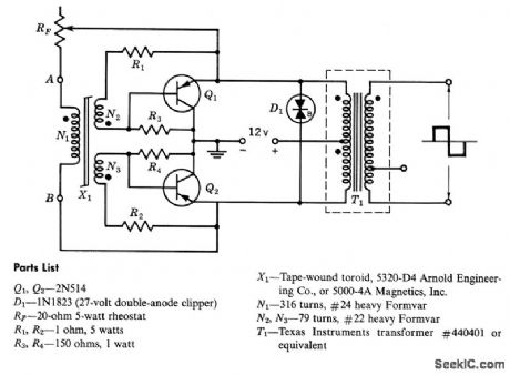
Provides square-wave output to load from 12-v d-c supply, at 130 v, with efficiency of 85%.-Texas Instruments Inc, Transistor Circuit Design, McGraw-Hill, N,Y,J1963,p 458. (View)
View full Circuit Diagram | Comments | Reading(658)
CASSETTE_INTERFACE_1
Published:2009/7/14 5:19:00 Author:May
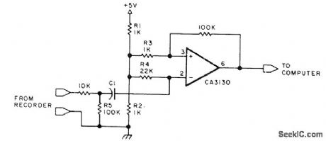
Used between recorder and computer for loading data stored in tape cassette. Single divider network R1-R2 drives both opamp inputs and provides stabilized sensitivity. R3 isolates inputs.-B. E. Rehm, The TDL System Monitor Board, BYTE, April 1978, p 10, 12-14, and 16. (View)
View full Circuit Diagram | Comments | Reading(652)
COMPOSITE_COLOR_SIGNAL_GENERATOR
Published:2009/7/15 3:18:00 Author:Jessie
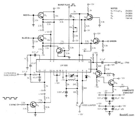
Single LM1889 encoder chip produces standard composite color video signal from separate sync.burst flag, 3.579545-MHz subcarrier and 0-4 V red, green, and blue inputs. Subcarrier should be 1-5 V P-P. Modulated RF output can go to cable input of TV set through 75-ohm cable. Applications include TV mixing and video games.-L. Trottier and B. Matic, Signal Encoder Generates Composite Color, EDN Magazine, Aug, 20, 1978, p 148 and 150. (View)
View full Circuit Diagram | Comments | Reading(2949)
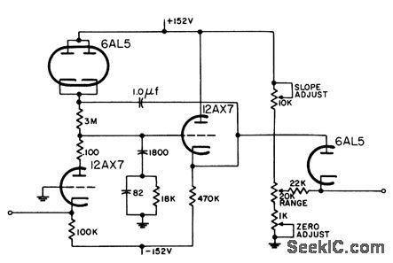
SINE_COSINE_APPROXIMATOR
Published:2009/7/15 3:17:00 Author:Jessie
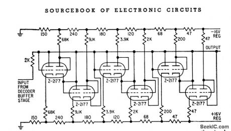
Converts triangular first approximation of sine and cosine of azimuth angle to accurate approximation of these functions by use of two diode-connected triodes as function generators, one for positive signals and the other for negative signals.-B.L. Bair, Logical Design of SAGE Input Monitor, Electronics,31:33, p 78-81. (View)
View full Circuit Diagram | Comments | Reading(717)
SQUARING_CIRCUIT
Published:2009/7/15 3:16:00 Author:Jessie
Fet gives higher accuracy and higher gain than ordinary transistors or vacuum lubes. At maximum input, output voltage is about three times input voltage. Used to measure mean-squared value of voltages from 5 cps to 100 kc.-Increase the Accuracy of Your Squaring Circuits with Silicon Field-Effect Transistors (Texas Instruments ad), EEE, 11:7, p 6-7. (View)
View full Circuit Diagram | Comments | Reading(795)
| Pages:144/471 At 20141142143144145146147148149150151152153154155156157158159160Under 20 |
Circuit Categories
power supply circuit
Amplifier Circuit
Basic Circuit
LED and Light Circuit
Sensor Circuit
Signal Processing
Electrical Equipment Circuit
Control Circuit
Remote Control Circuit
A/D-D/A Converter Circuit
Audio Circuit
Measuring and Test Circuit
Communication Circuit
Computer-Related Circuit
555 Circuit
Automotive Circuit
Repairing Circuit