
Basic Circuit
Index 155
CODING_DIGIT_CARD
Published:2009/7/14 3:27:00 Author:May
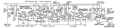
Initiate pulse starts coding in digit card of analog-digital converter and ultimately provides positive shift-carry pulse for next card. Codes inputs up to 5 v at maximum sampling rate of 5,000 inputs per second with 0.5% accuracy. Eight binary-digit result is shifted out serially at 100,000 digits per second.-W. B. Towles, Transistorized Analog-Digital Converter, Electronics,31:31, p 90-93. (View)
View full Circuit Diagram | Comments | Reading(724)
2712_MC_DIELECTRIC_HEATER
Published:2009/7/14 3:27:00 Author:May
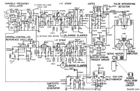
Pulse-controlled frequency-stabilization servo mechanism retunes self-excited power oscillator continually, with 200-cps mvbr governing rate at which system compares oscillator frequency with that of crystal-controlled reference oscillator.-J. Markus and V. Zeluff, Handbook of Industrial Electronic Control Circuits, McGraw-Hill, N.Y., 1956, p 173. (View)
View full Circuit Diagram | Comments | Reading(961)
MULTIPLIER_DIVIDER
Published:2009/7/14 3:25:00 Author:May
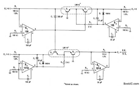
Upper half of circuit is log converter in which output at A1 is logarithmic ratio of E1 and E2. A3 and Q3 form second log converter for E3 input. Log output of second converter is added to that of upper circuit, producing log (E1 E3 /E2) at emitter of Q4.Q4 and A4 take antilog to give final output equal to E1 E3 / 10E2. If only multiplication is desired, E2 can be reference voltage; R4will then establish reference current.-W.G. Jung,″IC Oρ-Amp Cookbook,''Howard W Sams,Indianapolis,IN,1974,p 216-217. (View)
View full Circuit Diagram | Comments | Reading(0)
ANALOG_SAMPLE_HOLD_CIRCUIT
Published:2009/7/14 3:25:00 Author:May
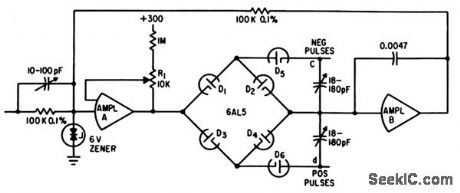
Uses diode bridge as switching circuit. Operational amplifier A delivers maximum current of 10 ma. Chopper-stabilized operational amplifier B delivers 100 v at 10 ma.-T. A. Brubaker, Precision Analog Memory Has Extended Frequency Response, Electronics, 34:39,p 141-143. (View)
View full Circuit Diagram | Comments | Reading(823)
TEMPERATURE_COMPENSATED_DECODER
Published:2009/7/14 3:24:00 Author:May
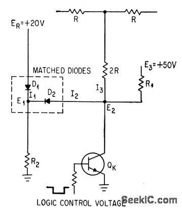
Matched diodes in ladder-type network decoder change one reference voltage of transistor switch to compensate for temperature effects-C. R. Pearman and A. E. Popodi, How to Design High-Speed D-A Converters,Electronics,37:8,p 28-32. (View)
View full Circuit Diagram | Comments | Reading(706)
PULSE_WIDTH_TO_ANALOG_DEMODULATOR
Published:2009/7/14 3:23:00 Author:May
Circuit integrates incoming pulse and holds final value until next pulse arrives, Output then returns to zero for next integration. Output range is 0 to 10 v for input pulse width range of 0 to 1 microsec.-D. Knowlton, Modulated Pulse Width Converted to Analog Voltage, Electronics, 38:20, p 99-100. (View)
View full Circuit Diagram | Comments | Reading(944)
COMPARATOR
Published:2009/7/14 3:22:00 Author:May
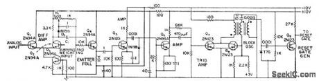
Comparator action begins when summing and weighting output exceeds analog input and negative pulse is coupled through C1. Trailing edge of blocking oscillator pulse activates reset-rate generator.-W.B. Towles, Transistorized Ancdog-Digital Converter, Electronics, 31:31, p 90-93. (View)
View full Circuit Diagram | Comments | Reading(1405)
CONTROL_FOR_SWITCHING_REGULATOR
Published:2009/7/14 3:19:00 Author:May
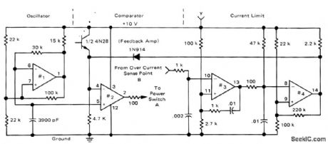
Uses all four sections of Motorola MC3302 quad comparator. First section is connected as 20-kHz oscillator that supplies sawtooth output sweeping between voltage limits set by 100K positive feedback resistor and 15-V supply. Section 2 compares sawtooth output to feedback signal, to produce variable-duty-cycle output pulse for power switch of switching regulator. Sections 3 and 4 initiate current-limiting action; section 3 senses over current and triggers section 4 connected as mono MVBR. Limiting occurs at about 4 A. When load short is removed, regulator resets automatically. Point A goes to push-pull drive for power switch of regulator, and point B goes to current-sensing resistor in output circuit of regulator. Point y goes to 10-V supply.-R. J. Bayer, A New Approach to Switching Regulators, Motorola, Phoenix, AZ, 1975, AN-719, p 7. (View)
View full Circuit Diagram | Comments | Reading(888)
TRANSISTORS_FOR_AF_TUBES
Published:2009/7/14 3:19:00 Author:May
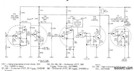
Article covers replacement of tubes in Drake T-4XB transmitter with solid-state equivalent circuits mounted in 7-pin and 9-pin miniature plugs,.Numbers identify original tube pins V1A and V2A use dual-cascode JFETs, while- operated transmitter relay control V2B and AM modulator V3 use high-voltage Darlington Q9 collector voltage is set at 150 V during standby by adjusting R9, Circuit includes first and second audio stages. Voltages indicate proper operating points. Source resistors may require adjustment.-H. J. Sartori, Solid-Tubes-a New Life for Old Designs, QST, April 1977, p 45-50.
(View)
View full Circuit Diagram | Comments | Reading(2135)
RANDOM_PULSE_CONVERTER
Published:2009/7/14 3:19:00 Author:May
Transforms random information, as from radiation counter and micrometeorite detector, into analog form suitable for multiplexing, and provides memory between events.-O. B. King, Multiplexing Techniques for Satellite Applications, Electronics, 32:44, p 58-62. (View)
View full Circuit Diagram | Comments | Reading(677)
CONTROLLING_REGULATOR_OUTPUT
Published:2009/7/14 3:18:00 Author:May
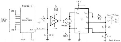
Digital control of D/A converter determines output voltage of regulator, with FET serving as voltage-variable resistor. Applications include generation of sequence of voltages for testing components or equipment. Analog Devices MDA-10Z-110 converter generates 0-2 mA output with resolution determined by 10-bit digital input. 741 opamp transforms current to 0-6 V output for varying output of 723 regulator over range of 7-37 V at 150mA maximum.-C. Viswanath, D-A Converter Controls Programmable Power Source, Electronics, July 21, 1977, p 125.
(View)
View full Circuit Diagram | Comments | Reading(1654)
POTENTIOMETER_ERROR_COMPUTER
Published:2009/7/14 3:17:00 Author:May
Compensation technique eliminates need for precise high-gain isolation amplifiers when linear potentiometers are used as precision voltage dividers in analog computing circuits. Error is reduced by factor of 100.-M. Kanner, How to Reduce Errors in Loaded Potentiometers, Electronics, 32:34, p 34-35. (View)
View full Circuit Diagram | Comments | Reading(795)
1_2_MHz
Published:2009/7/14 3:17:00 Author:May
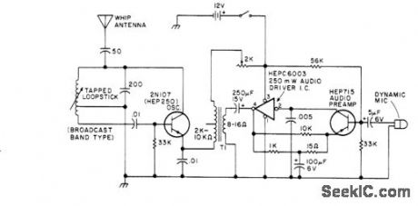
Simple low-power AM transmitter uses low-impedance output transformer in reverse to drive 2N107 oscillator stage for shortrange voice transmissions.-Circuits, 73 Magazine, June 1977, p 49. (View)
View full Circuit Diagram | Comments | Reading(817)
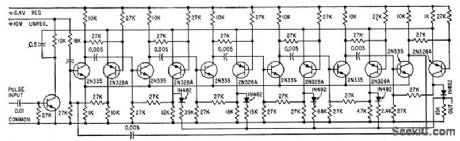
TEN_BIT_D_A_CONVERTER
Published:2009/7/14 3:17:00 Author:May
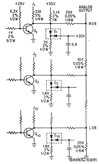
Ten identical stages (three are shown) use selected 2N2501 transistors and matched FA2054 clamping diodes to convert digital signals to equivalent analog voltages for driving servomotors, pen recorders, and deflection circuits of oscilloscopes.-C. R. Pearmcn and A. D. Popodi, How to Design High-Speed D-A Converters, Electronics, 37:8, p 28-32. (View)
View full Circuit Diagram | Comments | Reading(675)
FOUR_STATE_ATTENUATOR
Published:2009/7/14 3:16:00 Author:May
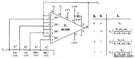
HA-2400 four-channel programmable amplfiier is used as non-inverting four-state attenuator controlled by logic inputs 0 and 1 to D0 and D1. Output voltage for each logic combination is given in truth table. Values shown provide gains of 1, 1/2, 1/4 and 1/8.-W. G. Jung, IC Op-Amp Cookbook, Howard W. Sams, Indianapolis, IN, 1974, p 429-431. (View)
View full Circuit Diagram | Comments | Reading(824)
VOLTAGE_REGULATOR
Published:2009/7/15 20:03:00 Author:Jessie
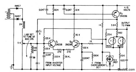
Portion of three-phase inverter output is filtered, rectified, und compared with temperature-compensated breakdown diode in differential amplifier Q1-Q2. Inverter load current and input battery voltage signals are also fed into differential amplifier, to further improve regulation.-R. J. Kearns and J. J. Rolfe, Three-Phase Static Inverters Power Space-Vehicle Equipment, Electronics, 34:18, p 70-73. (View)
View full Circuit Diagram | Comments | Reading(0)
PREFERRED_BISTABLE
Published:2009/7/15 6:03:00 Author:Jessie
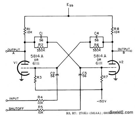
In response to negative trigger, generates voltage steps of opposite polarity at the two outputs. Has no timing function, so second trigger is needed to restore circuit to initial state. Used as radar gate. Requires 150 V plate supply For 6111 and 300 V for 5814A. -NBS, Handbook Preferred Circuits Navy Aeronautical Electronic Equipment, Vol. I, Electron Tube Circuit, 1963, PC 42, p 42-2. (View)
View full Circuit Diagram | Comments | Reading(671)
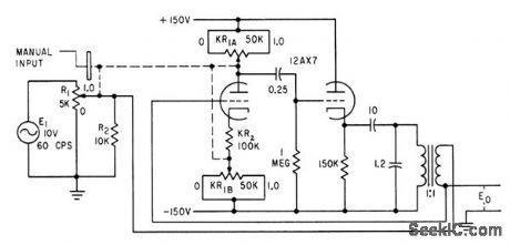
VOLTAGE_TO_TIME_CONVERTER
Published:2009/7/14 3:16:00 Author:May

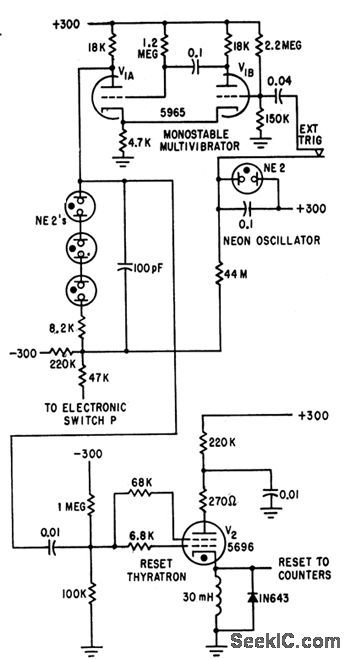
Produces output pulse whose width is accurately proportional to unknown input voltage. Pulses are then used to gate clock pulses into digital counters for voltage readout. Conversion occurs each time converter is switched on by monostable mvbr. Thyratron resets counters after each conversion.-B. Bcrker and M. McMahon, Digital Voltmeter Employs Voltage-To-Time Converter, Electronics, 34:18, p 67-69. (View)
View full Circuit Diagram | Comments | Reading(1067)
CRYSTAL_CONTROL_IMPROVES_STABILITY
Published:2009/7/15 6:02:00 Author:Jessie
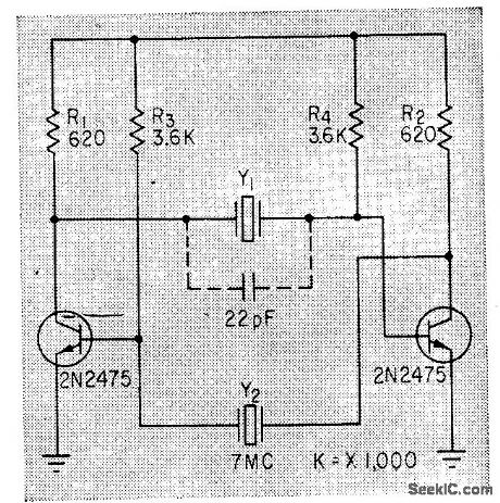
Use of 7-Mc crystal in place of feedback capacitors in conventional mvbr improves stability and waveform while still permitting operation down to 750 kc. Circuit also operates with one crystal; variable 7-47 pf capacitor in noncrystal-controlled side permits varying pulse width on this side over wide range.-H. R. Newhoff, Crystal-Controlled Multivibrator has Better Stability, Electronics, 36:15, p 60-61. (View)
View full Circuit Diagram | Comments | Reading(795)
PREFERRED_NONSATURATING_BISTABLE
Published:2009/7/15 6:00:00 Author:Jessie
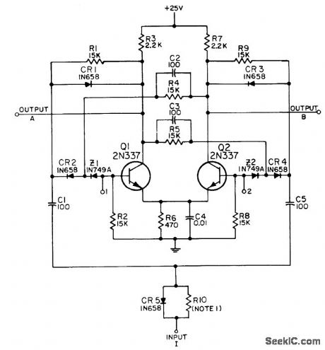
Used for frequency division of pulse trains when high stability is required. Cascade connection with appropriate feedback can provide any desired ratio. Also useful for coding, gating, and synchronizing. Maximum operating rate is up to 1 Mc.-NBS, Handbook Preferred Circuits Navy Aeronautical Electronic Equipment, Vol. II, Semiconductor Device Circuits, PSC 15 (originally PC 253), p 15-2. (View)
View full Circuit Diagram | Comments | Reading(712)
| Pages:155/471 At 20141142143144145146147148149150151152153154155156157158159160Under 20 |
Circuit Categories
power supply circuit
Amplifier Circuit
Basic Circuit
LED and Light Circuit
Sensor Circuit
Signal Processing
Electrical Equipment Circuit
Control Circuit
Remote Control Circuit
A/D-D/A Converter Circuit
Audio Circuit
Measuring and Test Circuit
Communication Circuit
Computer-Related Circuit
555 Circuit
Automotive Circuit
Repairing Circuit