
Basic Circuit
Index 142
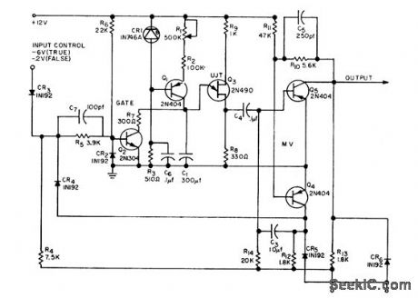
ISOLATING_DIODE_MONO_MVBR
Published:2009/7/15 2:46:00 Author:Jessie
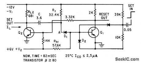
Addition of diode D1 to conventional delay circuit reduces timing variations otherwise encountered in production runs. Supply voltage change of 10% causes timing change of only 1%-D. E. Haselwood. Monostable Multivibrators with Stable Delay Times. Electronics.34:49,p64-65 (View)
View full Circuit Diagram | Comments | Reading(711)
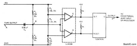
AUTOMATIC_RANGE_EXPANSIO_IV
Published:2009/7/14 7:48:00 Author:May
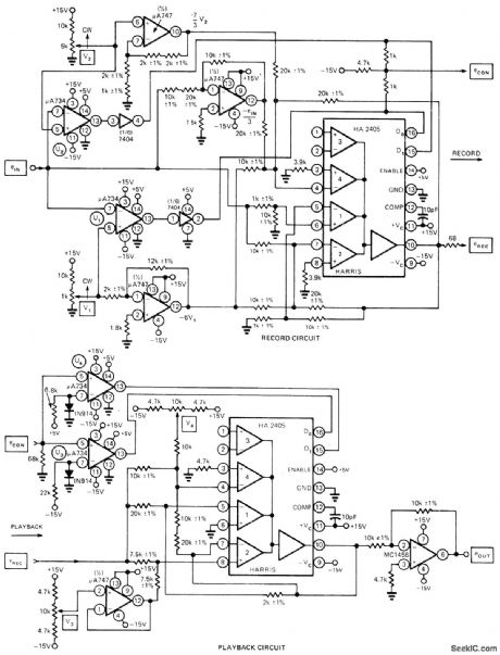

Instrumentation tape recorder technique folds recorded signal over and reuses same VCO range three times, at three different gains, for increasing dynamic recording range to over 10,000. Two comparators select one of three amplifier gains according to level of input signal and record selected gain on separate control track. During playback, control track signal eCON is used to select corresponding inverse gain for unfolding recorded signal. Level of input signal eIN, in range of 0-10 V, is sensed by comparators whose preset thresholds are determined by pots V1 and V2. If input is less than V1, both comparator outputs are low and section 1 of HA2405 four-channel opamp is selected for recording at 10 times input. If input is greater than V1 and less than V2, section 2 having gain of -2 is selected so direction of eREC is reversed. If eIN is greater than V2, both comparators are high and section 4 is selected for gain of +1/3, so eREC again reverses to cross VCO range for third time. Outputs of comparators are summed to form three-level signal for recording on control track.-J. R. White, Comparator Technique Expands Tape Recorder's Range, EDN Magazine, April 5, 1975, p 111, 113, and 115. (View)
View full Circuit Diagram | Comments | Reading(587)
1_HR_TIME_DELAY
Published:2009/7/15 2:42:00 Author:Jessie
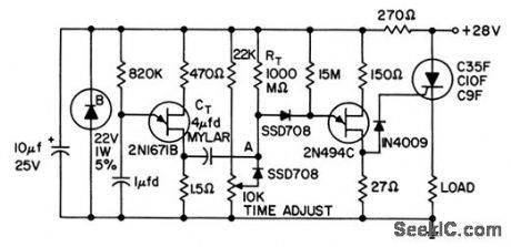
Achieved by periodically sampling voltage on timing capacitor, using sampling pulse generated by 2-cps ujt relaxation oscillator. Between samples, timing capacitor is isolated from emitter of ujt by low-leakage planar silicon diodes.- Transistor Manual, Seventh Edition, General Electric Co. 1964, p 321. (View)
View full Circuit Diagram | Comments | Reading(687)
PLAYBACK_OF_PULSE_TRAINS
Published:2009/7/14 5:37:00 Author:May
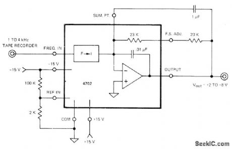
Teledyne Phil-brick 4702 frequency-to-voltage converter Circuit provides ripple filter required for converting recorded square waves in frequency range of 0.5 to 5 kHz to desired analog output in range of 2 to 8 VDC Report covers problems of recording and playing back pulse trains.-“V-F’s, V-F’s, and Audio Tape Recorders,” Teledyne Philbrick, Dedham, MA, 1974, AN-11. (View)
View full Circuit Diagram | Comments | Reading(1556)
OVERLOAD_PROTECTION
Published:2009/7/14 5:37:00 Author:May
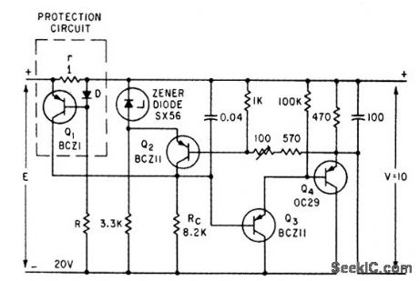
Protection circuit detects excessive load current and reduces output voltage proportionately. Values shown limit output current to 530 ma for short-circuit, while holding output voltage at 10 v during normal operation.-C. Yarker, Over. load Protection Circuit Uses low-Power Transistor, Electronics, 35:13, p 60. (View)
View full Circuit Diagram | Comments | Reading(2897)
M_ESSAGE_CONTROLLED_RECORDER
Published:2009/7/14 5:36:00 Author:May
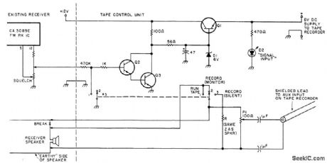
Circuit turns on tape recorder whenever input signal is present in receiver, and turns off recorder when signal goes off. Applications include monitoring local FM repeater for daily usage to obtain call signs of users, or unattended recording of messages left by other amateur stations, Uses cheap cassette tape recorder with autostop, operating at 6 V obtained from 12-V receiver sup-ply by series regulator Q1 and zener D1. Connection to mute or squelch circuit of receiver is shown for set having CA3089E in IF tail end. Darlington pair Q2-Q3 effectively removes base supply for on to turn recorder off. LED comes on when recorder is on. Q1 is NPN power transistor, while Q2 and Q3 are small-signal NPN transistors.-F. Johnson, Automatic Taping Unit, 73 Magazine, May 1977, p 98-99. (View)
View full Circuit Diagram | Comments | Reading(746)
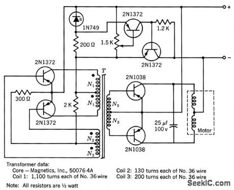
100_W_60_CPS_INVERTER
Published:2009/7/15 2:41:00 Author:Jessie
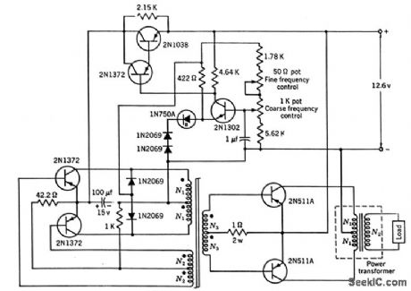
Permits operation of small a-c appliances from auto or boot storage battery. Frequency changes some what with temperature because sensing-input transistor (2N1302) is germanium.-Texas Instruments Inc, Transistor Circuit Design, McGraw-Hill, N,Y., 1963, p 457. (View)
View full Circuit Diagram | Comments | Reading(757)
50_MC_TO_400_MC_VARACTOR_MULTIPLIER
Published:2009/7/15 2:40:00 Author:Jessie
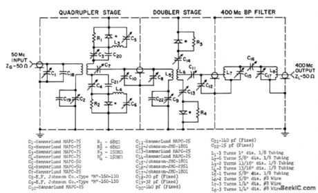
Consists of two push-push varactor circuits in cascade, with bandpass filter at output.Provides 40 w with 30% conversion efficiency; For pulse-modulated drive signals, will give 100 w peak pulse power at 0.0088 duty cycle. Uses Motorola 1N4386 varactors. -J. Cochran, Two-State Varactor Multiplier Provides High Power at 400 Mc, motorola Application Note AN-177, Aug. 1965. (View)
View full Circuit Diagram | Comments | Reading(901)
DOUBLERS_AND_TRIPLER
Published:2009/7/15 2:38:00 Author:Jessie

In left section, first two stages are class B common-base power doublers and last two AB common-emitter amplifiers. Output is 150 mw at 216 Mc input. In section at right, common-base class B power tripler drives common-emitter output amplifier to give 140 mw output at 162 Mc from 54-Mc input.-J.W. Hamblen and J. B. Oakes, Instrumentation and Telemetry of Transit Navigational Satellites,Electronics,34:32, p 148-153. (View)
View full Circuit Diagram | Comments | Reading(713)
FIXED_BOOTSTRAP_DELAY
Published:2009/7/15 2:37:00 Author:Jessie
Used to provide buffer interval between sync and video information in radar relay transmitter. Requires gate at least as long as 30-microsec delay. Accuracy is only 10%.-NBS, Hand-book Preferred Circuits Navy Aeronautical Electronic Equipment, Vol.1, Electron Tube Circuits, 1963, p N9-1. (View)
View full Circuit Diagram | Comments | Reading(656)
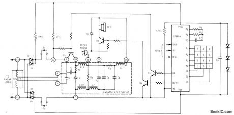
DUAL_TONE_SIGNALING
Published:2009/7/14 6:51:00 Author:May
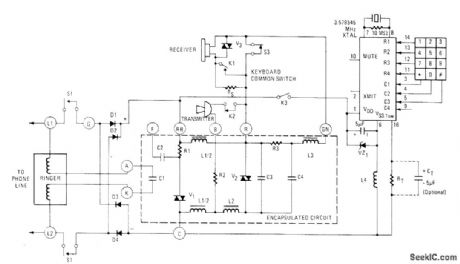
American Microsystems S2559 digital tone generator IC at upper right interfaces directly with encapsulated 500-type telephone set to give pushbutton dualtone telephone. Diodes D1-D4 are added to telephone set to ensure that polarity of direct voltage across device is unchanged even if connections to phone terminals are reversed, Generator IC requires external crystal feeding programmable dividers to give eight standard audio frequencies with high accuracy for combining in pairs as required for dual-tone signaling.- Digital Tone Generator, American Microsystems, Santa Clara, CA, 1977, S2559, p 11. (View)
View full Circuit Diagram | Comments | Reading(1662)
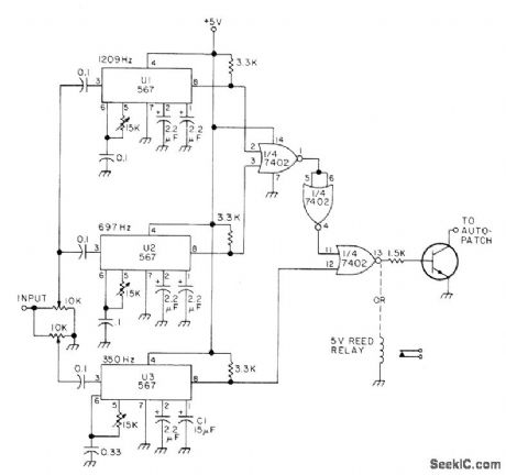
TOLL_CALL_KILLER
Published:2009/7/14 6:50:00 Author:May

Prevents unauthorized direct long-distance dialing through repeater autopatch from areas where 1 must be dialed ahead of desired out-of-town phone number. Based on simultaneous detection of 350-Hz component of dial tone and 1209- and 697-Hz tones assigned to 1 in Touch-Tone system. Circuit requires only three 567 tone decoders, 7402 quad gate, and either transistor or relay for controlling autopatch. Article covers installation and operation.-W. J. Hosking, Long Distance Call Eliminator, 73 Magazine, April 1976, p 44-45. (View)
View full Circuit Diagram | Comments | Reading(740)
PLL_SINGLE_TONE_DECODER
Published:2009/7/14 6:49:00 Author:May
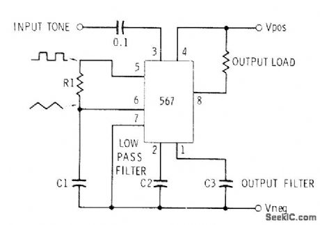
Can be used for Touch-Tone decoding as well as for telephone-line and wireless control applications using single audio frequency. Operating center frequency depends on H1 and C1. R1 should be between 2K and 20K. C1 in microfarads is computed from f = 1/R1C1, where R is in megohms and f is in hertz. C2 is low-pass filter in range of 1-22μF; the larger its value, the narrower its bandwidth. C3 is not critical and can be about twice C2.-C. D. Rakes, Integrated Circuit Projects, Howard W. Sams, Indianapolis, IN, 1975, p 68-73. (View)
View full Circuit Diagram | Comments | Reading(925)
HIGH_VOLTAGE_PULSE_DELAY
Published:2009/7/15 2:36:00 Author:Jessie

Diode input network isolates base of Q1 from input when input pulse voltages exceed maximum rated emitter-to-base reverse voltage of input inverting digital pulse delay circuit.-R. A. Karlin, One-Transistor Multi Delays Digital Pulses, Electronics, 38:17, p 85-86. (View)
View full Circuit Diagram | Comments | Reading(1151)
INTERFACE_FOR_AUDIO_CASSETTES
Published:2009/7/14 6:42:00 Author:May
Permits use of ordinary home cassette recorder to provide high-speed loading of assembler and source program into microprocessor. Data is recorded by using variation of phase encoding, which provides self-clocking and is independent of tape speed variation. Effective I/O rate is about 500 b/s or 5 times that of low-speed paper-tape punch or reader. Article covers phase-encoding procedure, gives flowchart, and shows waveforms of pulses at five points in circuit. Parity bits provide error correction and detection, using Hamming code.-S. Kim, An Inexpensive Audio Cassette Recorder Interface for, μP's, EDN Magazine, March 5, 1976, p 83-86. (View)
View full Circuit Diagram | Comments | Reading(696)
KEY_PULSER
Published:2009/7/14 6:16:00 Author:May
American Microsystems S2560A CMOS IC pulser converts pushbutton inputs to series of pulses suitable for telephone dialing, as replacement for mechanical telephone dial. Circuit shows typical connection to dial telephone set using 500-type encapsulated circuit. Dialing rate can be varied by changing dial rate oscillator frequency. IC includes 20-digit memory that makes last dialed number available for redialing until new number is entered, Entered digits are stored sequentially in internal memory, with dial pulsing starting as soon as first digit is entered. Arrangement permits entering digits much faster than output rate. Last number is redialed by going off hook and pressing # key.- Key Pulser, American Microsystems, Santa Clara, CA, 1977, S2560A/S2560B, p 8. (View)
View full Circuit Diagram | Comments | Reading(1585)
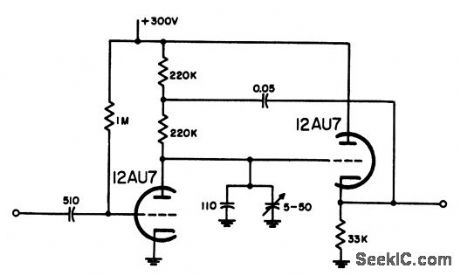
STABLE_ENCODER
Published:2009/7/14 6:15:00 Author:May
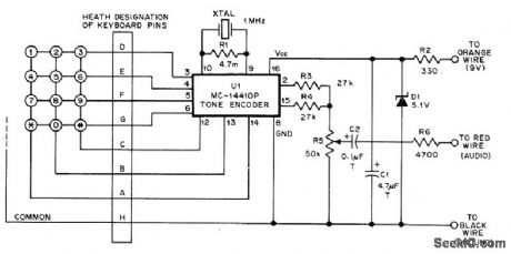
All tones are frequency-synthesized and held within tolerance of 0.2% by using Motorola MC14410P CMOS tone-en-coder chip which is digital synthesizer requiring only 1-MHz reference crystal and nine other external parts. Circuit is redesign of Heath Mi-coder for triggering autopatch of repeater during mobile operation. Operates from 9-V battery. Audio output matches input for low-impedance microphone. For higher output, increase R3 and R4.-G. K. Fallenbeck, Mycoder, QST, April 1978, p 27-29. (View)
View full Circuit Diagram | Comments | Reading(850)
FOUR_MINUTE_DELAY
Published:2009/7/15 2:34:00 Author:Jessie
Ujt switch gives accuracy of 1% for time delays in range of 1 to 4 minutes, over range of 10℃ above and below 25℃. R1 controls amount of delay.-E. G. McCoy, Accurate Time Delays up to Four Minutes, EEE, 11:10, p 31. (View)
View full Circuit Diagram | Comments | Reading(719)
20_W_60_CPS_INVERTER
Published:2009/7/15 2:33:00 Author:Jessie
Low-power version was designed to drive timer. Maximum frequency variation was only 1 % for supply-voltage range of 11.5 to 14.5 v.-Texas lnstruments lnc,, Transistor Circuit Design, McGrctw4iill, N.Y., 1963,p458. (View)
View full Circuit Diagram | Comments | Reading(835)
CASSETTE_INTERFACE_WITH_ACIA
Published:2009/7/14 7:31:00 Author:May
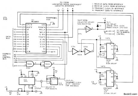
Permits use of audio pickup for mass storage in Motorola 6800 microcomputer system. Uses Motorola MC6850 asynchronous communication interface adapter (ACIA), which is specialized version of UART. All control, status, and data transfers in ACIA are made over single 8-bit bidirectional bus. Request-to-send line (RTS) controls tape recorder motor. When RTS is set high, input to IC8 is high and relay coil is not energized. IC6 gives 5-s delay following motor turn-on so long leader will be recorded at mark frequency. IC7 gives delay so reading starts 2.5 s before first data byte. Article covers circuit operation in detail and gives operating subroutines.-J. Hemenway. The Compleat Tape Cassette Interface, BYTE, March 1976, p 10-16. (View)
View full Circuit Diagram | Comments | Reading(3239)
| Pages:142/471 At 20141142143144145146147148149150151152153154155156157158159160Under 20 |
Circuit Categories
power supply circuit
Amplifier Circuit
Basic Circuit
LED and Light Circuit
Sensor Circuit
Signal Processing
Electrical Equipment Circuit
Control Circuit
Remote Control Circuit
A/D-D/A Converter Circuit
Audio Circuit
Measuring and Test Circuit
Communication Circuit
Computer-Related Circuit
555 Circuit
Automotive Circuit
Repairing Circuit