
Basic Circuit
Index 156
CATHODE_COUPLED_TRIGGER
Published:2009/7/15 5:58:00 Author:Jessie
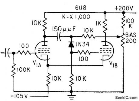
Series diode improves sensitivity for cathode-coupled monostable mvbr while giving stability of 5% for threshold levels of several mv. Second tube can be triode, permitting use of 6U8 triode-pentode in compact assembly.-M. M. Vojinovic, Series Diode Increases Multivibrator Sensitivity, Electronics, 32:17, p 90-91. (View)
View full Circuit Diagram | Comments | Reading(753)
RELAY_MVBR_WITH_ISOLATOR_DIODES
Published:2009/7/15 5:56:00 Author:Jessie
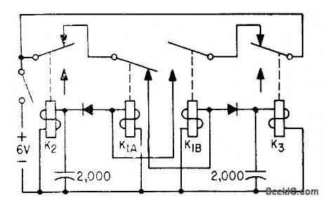
Use of diodes to isolate capacitors reduces capacitance requirements for low frequencies. High-resistance relays for K2 and K3 cut costs.-R. L. lves, Multivibrator for Low Frequencies Uses Relays, Electronics, 34:32, p 166-169. (View)
View full Circuit Diagram | Comments | Reading(834)
SIMPLE_FREQUENCY_SYNTHESIZER
Published:2009/7/14 3:11:00 Author:May
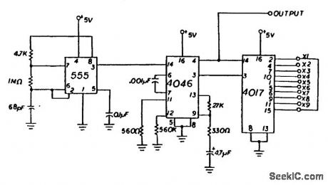
The 555 timer circuit is configured as a 10-kHz astable multivibrator that feeds this signal to the 4046 phase-locked-loop IC. The signal that is fed from this chip is then coupled to a divide-by-N counter. This counter will take the 10-kHz signal locked on by the 4046 and will produce multiples of the fundamental frequency(10 kHz). Therefore, it is possible to generate frequencies as high as 100 kHz with this circuit. When building this circuit, remember to use safety precautions when handling CMOS chips. (View)
View full Circuit Diagram | Comments | Reading(5935)
PULSE_EDGE_SELECTOR
Published:2009/7/15 5:37:00 Author:Jessie
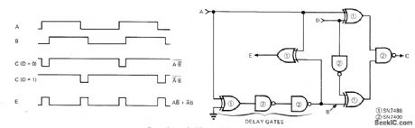
Two quad TTL packages form simple circuit that generates output pulse at C as function of either leading or trailing edge of input pulse at A, depending on logic level at terminal D. Additional output at E supplies pulses coinciding with both leading and trailing edges of input, independently of logic level at D. Maximum input frequency is 10 MHz, and edge pulses are about 35 ns wide. IC1 is quad two-input EXCLUSIVE-OR gate, and IC2 is quad two-input NAND gate.-C. F. Reeves, A Programmable Pulse-Edge Selector, EDN Magazine, April 20, 1973, p 85 and 87. (View)
View full Circuit Diagram | Comments | Reading(825)
100_dB_DYNAMIC_RANGE
Published:2009/7/14 3:11:00 Author:May
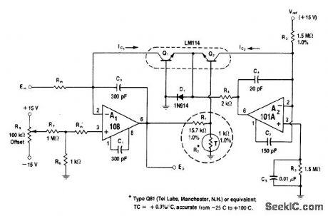
Circuit generates log ratio of currents Ic1, and Ic2, with accuracy within 3% from 10 nA to 1 mA (100dB range) when Ic2 is fixed at 10-μA reference value. Accuracy increases to 1% for current inputs between 40 nA and 400 μA (80 dB). A2 supplies constant reference current to Q2.Q1 is operated as transdiode withQ2 providing temperature compensation of offset voltage.-W. G. Jung, IC Op-Amp Cookbook, Howard W. Sams, Indianapolis, IN, 1974 ,p 213-214. (View)
View full Circuit Diagram | Comments | Reading(802)
COMPLETING_LAST_CYCLE
Published:2009/7/15 5:34:00 Author:Jessie
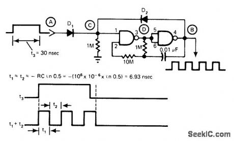
Developed for applications requiring that gated oscillator must always complete its timing cycle. Circuit uses only two NAND gates and two diodes, none of which are critical as to type. With no input at A, oscillator output B is low. When A is driven high, D goes low initially and drives output B high. If input at A is removed, regenerative feedback is applied from B through diode D2 to C until normal timing cycle is finished. Then, with B low, D becomes high and keeps output B low.-L. P. Kahhan, Gated Oscillator Completes Last Cycle, EDN Magazine, Jan. 5, 1977, p 43. (View)
View full Circuit Diagram | Comments | Reading(788)
ENCODER
Published:2009/7/14 3:09:00 Author:May
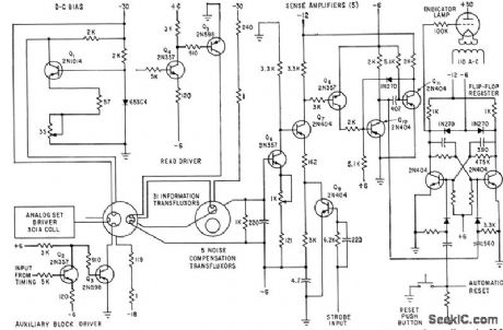
Used between fransfluxor and digital shift register of converter that changes analog inputs to six-bit binary Gray code.-N. Aron and C. Granger, Analog-To-Digital Converter Uses Transfluxors,Electronics,35:20,p 62-66. (View)
View full Circuit Diagram | Comments | Reading(940)
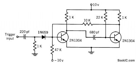
POLARITY_DETECTOR
Published:2009/7/14 3:07:00 Author:May
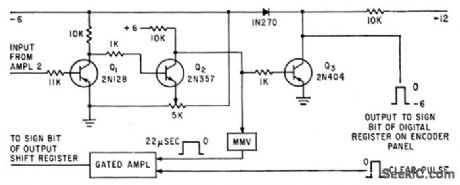
Q1-Q2 amplify negative analog samples greater than 100 mv, to provide sharp pulse output for driving monostable mvbr in analog-digital converter.-N, Aron and C, Granger, Analog-To-Digital Converter Uses Transfluxors Electronics, 35:20, p 62-66. (View)
View full Circuit Diagram | Comments | Reading(1029)
150_KC_BISTABLE
Published:2009/7/15 5:29:00 Author:Jessie
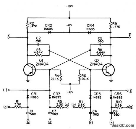
Designed as storage element in digital logic circuits for computer, control, and communication equipment. Can be used as counter and as serial or parallel shift register at operating rates up to 150 kc under maximum load. Article gives connections of lettered terminals for various circuit functions and performance characteristics.-NBS, Handbook Preferred Circuits Navy Aeronautical Electronic Equipment, Vol. II, Semiconductor Device Circuits, PSC 9 (originally PC 212), p 9-2. (View)
View full Circuit Diagram | Comments | Reading(715)
STEPPING_5_V_UP_TO_15_V
Published:2009/7/14 3:05:00 Author:May
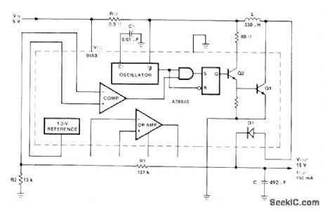
Fairchild μA78S40 switching regulator transforms 5 V to 15 V at efficiency of 80% for 150-mA load. Average input current is only 550 mA. Article gives de-sign equations.-R. J. Apfel and D. B. Jones, Universal Switching Regulator Diversifies Power Subsystem Applications, Computer Design, March 1978, p 103-112. (View)
View full Circuit Diagram | Comments | Reading(577)
10_MICROSEC_MONOSTABLE_MVBR
Published:2009/7/15 5:28:00 Author:Jessie
Output pulse width is approximately 10 microsec with values shown for basic one-shot. -Texas Instruments Inc., Transistor Circuit Design, McGraw-Hill, N.Y., 1963, p 381. (View)
View full Circuit Diagram | Comments | Reading(956)
_10V_SWITCHING
Published:2009/7/14 3:03:00 Author:May
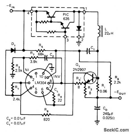
Uses LM304 regulator and Unitrode hybrid power switch in PIC600 series to provide output of 10 A. R1 and R2 determine reference voltage. Current limiting is achieved by reducing reference voltage to ground instead of turning off base drive to power output switch. Article covers operating theory.-L. Dixon and R. Patel, Designers' Guide to: Switching Regulators, EDN Magazine, Oct. 20, 1974, p 53-59. (View)
View full Circuit Diagram | Comments | Reading(969)
FET_VOLTAGE_COMPARAIOR
Published:2009/7/14 3:03:00 Author:May
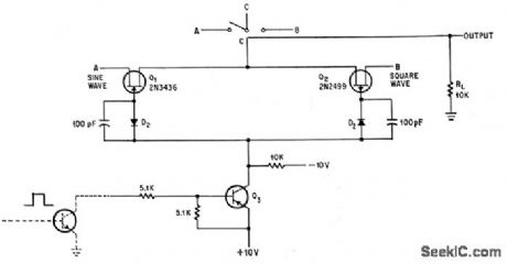
Circuit uses spdt configuration. Used to switch reference voltage (such as ground) to successive points on binary voltage ladder until comparator determines that output of ladder is equal to that of unknown voltage. Sine and square wave inputs at A and B produce output at C. Used also for low-level differential switching.-J. Gulbenk and T. F. Prosser, How Modules Make Complex Design Simple, Electronics, 37:32, p 50-54. (View)
View full Circuit Diagram | Comments | Reading(702)
PROGRAMMABLE_FREQUENCY_STATE_VARIABLE
Published:2009/7/14 3:03:00 Author:May
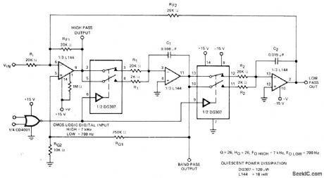
Provides choice of low-pass, high-pass, and bandpass out puts with logic-selectable center frequency of 700 or 7000 Hz. Logic input controls DG307 low-power dual analog switch for changing values of frequency-determining resistors R1 and R2.-″Analog Switches and Their Applications,″Siliconix, Santa Clara,CA,1976, p 7-86. (View)
View full Circuit Diagram | Comments | Reading(867)
TUNNEL_DIODES_READ_5_APERTURE_CORE
Published:2009/7/14 3:02:00 Author:May
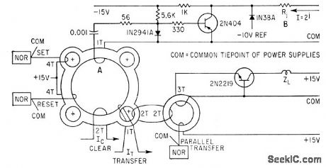
Circuit also controls switching of binary weighted current generators used in analog-digital converter. W. G. Trabold, Tunnel Diodes Save Parls-Continuous Readout of Magnetic Cores, Electronics, 36:36, p 38-39. (View)
View full Circuit Diagram | Comments | Reading(737)
WEIGHTING_CIRCUIT
Published:2009/7/14 3:00:00 Author:May
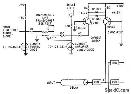
Circuit introduces precise amount of current into point P within few nsec in response to output of threshold tunnel diode, contributing to accurate conversion of wideband analog signals into 64 levels that are described by six bits of binary language.-H. R. Schindler, Semiconductor Circuits in a UHF Digital Converter, Electronics, 36;35, p 37-40. (View)
View full Circuit Diagram | Comments | Reading(865)
ANTILOG_CONVERTER
Published:2009/7/14 3:00:00 Author:May
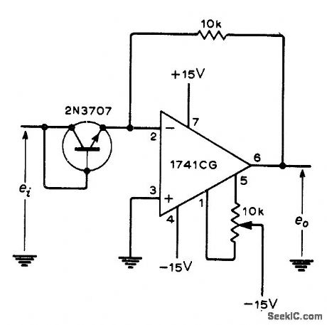
Basic opamp circuit with diode-connected transistor as logging element performs antilog conversion for positive input signals. For negative inputs, roverse transistor connections.-G. B. Clayton, Experiments with Operational Amplifiers, Wireless World, Jan. 1973, p 33-35. (View)
View full Circuit Diagram | Comments | Reading(2299)
DIGITALLY_SELECTABLE_GAIN
Published:2009/7/14 2:59:00 Author:May
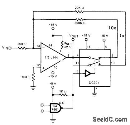
TTL controls operation of DG301 low-power analog switch at output of inverting opamp. Low logic gives gain of 1, and high logic gives gain of 10.- Analog Switches and Their Applications, Siliconix, Santa Clara, CA, 1976, p 7-90.
(View)
View full Circuit Diagram | Comments | Reading(896)
50_MC_SAMPLING_AND_THRESHOLD_CIRCUIT
Published:2009/7/14 2:58:00 Author:May
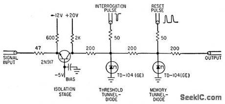
Threshold tunnel diode receives signal current to be sampled and interrogation pulses repeating at 50 Mc. Diode fires when signal current is below threshold level, making memory tunnel diode switch into its high-voltage state. Current level differences of less than 50 microamp can be resolved in 0.3 nsec, sufficient for converting input into six bits corresponding to 64 levels.-H. R. Schindler, Semiconductor Circuits in a UHF Digital Converter, Electronics, 36:35, p 37-40.
(View)
View full Circuit Diagram | Comments | Reading(860)
LOGAMP
Published:2009/7/14 2:58:00 Author:May
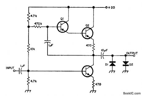
Based on fact that back-to-back diodes driven by current generator give output that varies logarithmically with input signal.With values shown, relation is logarithmic over 60-dB range.Transistors are 2N2924,SK3019,GE-10,or HEP-54,and diodes are 1N914,-Circults,73Magazine, April 1974,ρ 34.
(View)
View full Circuit Diagram | Comments | Reading(1025)
| Pages:156/471 At 20141142143144145146147148149150151152153154155156157158159160Under 20 |
Circuit Categories
power supply circuit
Amplifier Circuit
Basic Circuit
LED and Light Circuit
Sensor Circuit
Signal Processing
Electrical Equipment Circuit
Control Circuit
Remote Control Circuit
A/D-D/A Converter Circuit
Audio Circuit
Measuring and Test Circuit
Communication Circuit
Computer-Related Circuit
555 Circuit
Automotive Circuit
Repairing Circuit