
Basic Circuit
Index 159
SUMMING_AND_WEIGHTING_NETWORK
Published:2009/7/14 2:38:00 Author:May
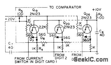
Consists of eight identical circuits. Precise value of direct current from constant-current source, fed into first node of resistive ladder network, produces 2.5-v step at summing and weighting network output, or half of maximum analog input of 5 v.-W.B. Towles, Transistorized Analog-Digital Converter, Electronics, 31:31, p 90-93. (View)
View full Circuit Diagram | Comments | Reading(783)
BCD_CONTROL_OF_GAIN
Published:2009/7/14 2:38:00 Author:May
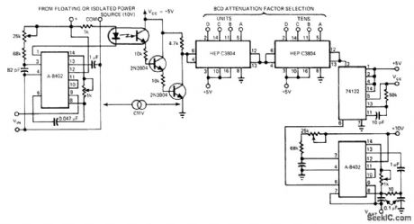

Provides optically coupled input and BCD-selected attenuation factor, for combination with fixed-gain DC amplifier to give programmable gain capability. Output of A-8402 V/F converter feeds programmable modulo-n decade counter chain through optoisolator, to give frequency division by BCD factor applied to selector inputs. 74122 retriggerable mono MVBR makes duty cycle of counter output compatible with requirements of second converter connected to give output voltage that is scaled reproduction of input voltage. Circuit performance is comparable to that of high-cost instrumentation amplifier.-K. W. Kissinger, Low-Cost Isolation Amp Provides BCD-Selectable Gain, EDN Magazine, Oct. 20, 1977, p 82-83. (View)
View full Circuit Diagram | Comments | Reading(766)
1_W_ON_175_kHz
Published:2009/7/14 2:32:00 Author:May
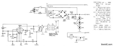
Simple one-tube circuit with zener-regulated power supply provides amateur CW operation in30-kHz segment of long wave (VLF) spectrum Adjust L1 and L2 to resonance with crystal used, then adjust coupling between them until meter between plate and ground reads correct current for legal limit of 1-W power input to final stage. Antenna is vertical mast insulated from ground, with transmitter directly at its base,-J. V. Hagan, A Crystal-Con-trolled Converter and Simple Transmitter for 1750-Meter Operation,QST, Jan. 1974, p 19-22. (View)
View full Circuit Diagram | Comments | Reading(878)
50_WPUSH_PULL
Published:2009/7/14 2:30:00 Author:May
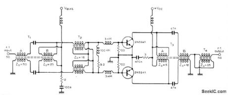
Single RF power amplifier stage uses broadband transmission-line transformers, operates between 50-ohm source and load impedances, and produces 50 W peak envelope power from 28-V supply over band of 2-30 MHz. Article gives design equations for toroid transformers.-W. P .Reilly, Transmitter Power Amplifier Design, Wireless world, Sept1975, p 417-422. (View)
View full Circuit Diagram | Comments | Reading(1168)
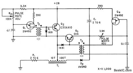
VARIABLE_WIDTH_TO_1285_MHz
Published:2009/7/15 22:02:00 Author:Jessie
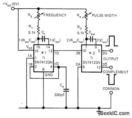
Single IC circuit uses two monostables to form pulse generator that covers over eight decades (0.054 Hz to 12.85 MHz) with only eight capacitors. Similarly, only eight capacitors cover pulse width range of over eight decades (60 ns to 18 s). Voltage control of frequency and pulse width can be obtained by connecting R2 and R4 to individual 1.5-4.5 V control voltage lines instead of to VCC. Frequency will then vary almost linearly with control voltage, while pulse width will vary almost inversely with control voltage. Capacitor values range from 1 pF to over 100 μF. -M. J. Shah, Wide-Range Pulse Generator Uses Single IC, EDN Magazine, Jan. 5, 1973, p 107 and 109. (View)
View full Circuit Diagram | Comments | Reading(1882)
SYNCHRONIZATION_TO_10_MHz
Published:2009/7/15 22:00:00 Author:Jessie
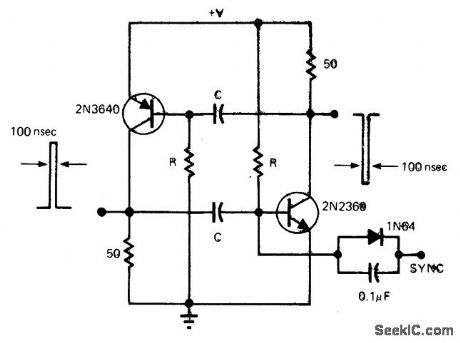
Free-running pulse generator circuit uses diode to inhibit operation until sync signal is applied. Circuit then pulses until sync signal returns to original state. Complementary outputs having pulse widths of 100 ns swing essentially from ground to power supply voltage that can be anywhere in range from 0.65 V to 15V. Values used for R and C determine frequency. For oscillation, R must be in range of 1 kilohm to 1 megohm. For 5-V supply, frequency is 1.2/RC.-B. Shaw, Oscillator Provides Fast, Low Duty-Cycle Pulses, EDN Magazine, March 20, 1975, p 73. (View)
View full Circuit Diagram | Comments | Reading(1099)
PULSE_STRETCHER_WITH_ISOLATION
Published:2009/7/15 21:49:00 Author:Jessie
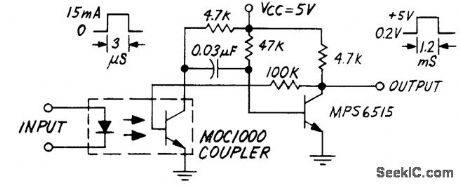

Motorola MOC1000 optoisolator provides safe inter-facing with digital logic while stretching input pulse. Circuit uses phototransistor of optoisolator as one of transistors in mono MVBR. With input pulse width of 3 μs, output pulse width is about 1.2 ms. - Industrial Control Engineering Bulletin, Motorola, Phoenix, AZ, 1973,EB-4. (View)
View full Circuit Diagram | Comments | Reading(1132)
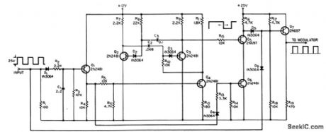
ADJUSTABLE_CURRENT_LIMITER
Published:2009/7/15 23:17:00 Author:Jessie
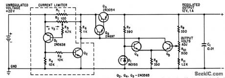
Q1 conducts when current exceeds limiting value deter-mined by setting of R3, turning on Q2 and in effect grounding base of Q6, to prevent significant current flow in Q3. Circuit resets automatically when overload is removed.-P. Galluzzi, Adjustable Current Limiter for Regulated Power Supply, Electronics, 395, p 107. (View)
View full Circuit Diagram | Comments | Reading(3371)
MONO_DESIGN
Published:2009/7/15 23:20:00 Author:Jessie
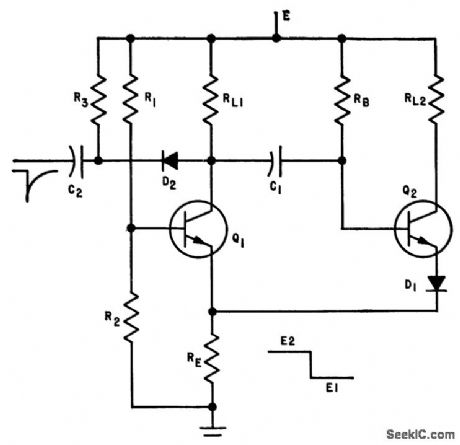
Simplified equations are given for designing emitter-coupled monostable mvbr. With 20-V supply, component values for use with 2N388 transistors to provide 25-microsec pulse width, for E1=4 V and E2 =7 V are RE=1K, RL2=1,800 ohms, RL1 = 3,900 ohms, R1 = 56,000 units, R2=27,000 ohms, and C1= 620 pf.-L. I. Kleinberg, Designing Emitter-Coupled Monostable Multivibrators, Electronics, 34:39, p 86. (View)
View full Circuit Diagram | Comments | Reading(1203)
GATED_DELAY
Published:2009/7/16 1:47:00 Author:Jessie
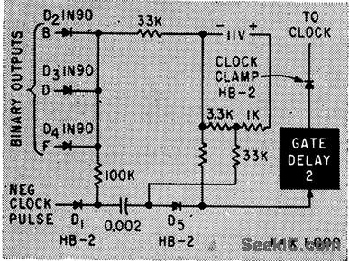
Negative output dock pulses of 256-pctmmeter microwave system checker are applied to gaing diode D1, which ordinarily blocks signal to delay mvbr. During eighth pulse of code train, diodes D2-D3-D4 receive negative voltage from their binary outputs and make D1 trigger mvbr through D5. At end of mvbr delay, damp is removed until eight more pulses arrive.-J. B. Bullock, Pulse-Coded Fault Alarm in Microwave Systems, Electronics, 33:1, p 82-84. (View)
View full Circuit Diagram | Comments | Reading(697)
AM_SUPERHET_SUBSYSTEM
Published:2009/7/15 22:44:00 Author:Jessie
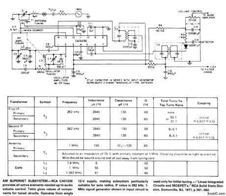

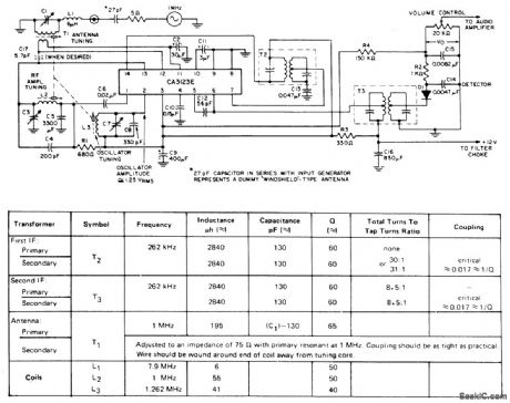
RCA CA3123E provides all active elements needed up to audio volume control Table gives values of components for tuned circuits Operates from single 12-V supply, making subsystem particularly suitable for auto radios. IF value is 262 kHz. 1-MHz signal generator shown in input circuit is used only for initial tuning.- Linear Integrated Circuits and MOS/FET's , RCA Solid State Division, Somerville, NJ 1977, p 361-362.
(View)
View full Circuit Diagram | Comments | Reading(1020)
4_W_AT_150_V_FROM_FLASHLIGHT_CELL
Published:2009/7/15 22:44:00 Author:Jessie
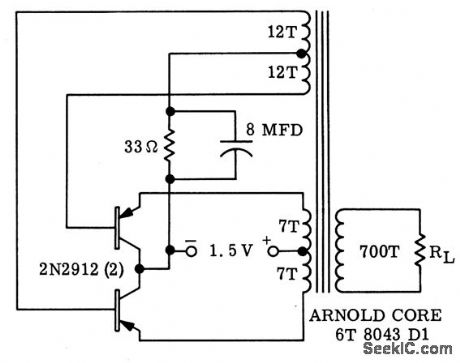
Portable supply operates at 80% efficiency through use of rapid-switching transistors.-H. F. Weber, Low Voltage Inverter Features High Frequency Operation with High Efficiency, Motorola Application Note AN.174, Feb. 1966. (View)
View full Circuit Diagram | Comments | Reading(792)
INVERTER_WITH_CAPACITOR_TURNOFF
Published:2009/7/15 22:43:00 Author:Jessie
Load power factor variations do not affect turnoff time. Varying trigger rate of Q2 varies power delivered to R1. Trigger rate can be adjusted automatically for load regulation.-D. V. Jones, Turn-Off Circuits for Controlled Recliners, Electronics, 33:32, p 52-55. (View)
View full Circuit Diagram | Comments | Reading(729)
DUTY_CYCLE_LIMITER
Published:2009/7/15 23:23:00 Author:Jessie
When duty cycle exceds 1%, countdown begins and duty cycle is held at about 1%. Uses voltage-controlled useable mvbr consisting of Q2, Q3, and Q4, which runs unsynchronized with input prf.-C. Samocki, Duty-Cycle Limiter, EEE, 13:9, p 76. (View)
View full Circuit Diagram | Comments | Reading(1093)
ACTIVE_LOAD_RESISTOR
Published:2009/7/15 23:22:00 Author:Jessie
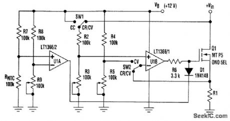
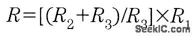
The design idea presented here concerns an active power resistor. It can be used as a load resis-tor when probing or servicing power supplies. The circuit can work in three different modes. It can act as a constant resistor (mode CR), or as a constant current from a supply of any positive voltage. Finally, it can be in constant-voltage mode (CV), in which the circuit loads the voltage across supply terminals to a constant value adjusted by the user. The power MOSFET transistor Q1 works as a resistive component. The transistor gate is controlled by an op amp (U1B). The feedback voltage, which can be selected by switch SW2, is connected to the amplifier's inverting input. In CC and CR modes, the feedback voltage is the voltage between the source resistor (R1) terminals, which is proportional to the amplifier supply voltage (VB) through a voltage-divider circuit (R4-R5). The amplifier noninverting input is controlled by a control voltage. The control-voltage input can be selected by switch SW1. In CR and CV modes, that input is the resistor input voltage (Vin), and in CC mode, it is the amplifier supply voltage (VB). The control voltage is set in voltage divider R2-R3 to a proper value to control the amplifier. The other op amp (U1A) protects the MOSFET transistor. It is con-trolled by a resistor bridge circuit consisting of three resistors (R7 through R9) and an NTC resistor. The NTC is in contact with the transistor cooling element. With moderate element temperatures, the output voltage of U1A is high, and thus has no effect on the transistor gate because of the reverse-biased diode (D1). If the element temperature becomes high, the amplifier output has a zero value, which takes the transistor gate voltage to zero through the diode. The amplifiers also can be powered directly from the resistor input voltage. This circuit can work in CR mode without any control voltage. In CC and CV modes, however, it should be controlled by the external voltage CC/CV input. The circuit acts in CR mode as a resistor that has a resistance of
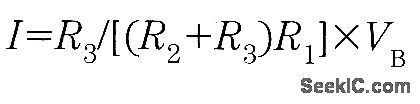
The required resistance value can be adjusted by potentiometer R3. In CC mode, the circuit sinks a current The sink current
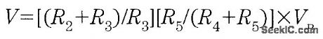
also can be adjusted by potentiometer R3 In CV mode,the voltane between theLerminals of the resistor is:
The required constant voltage can be adjusted by both R3 and R5 (View)
View full Circuit Diagram | Comments | Reading(5620)
SYMMETRICAL_LIMITER
Published:2009/7/15 23:22:00 Author:Jessie
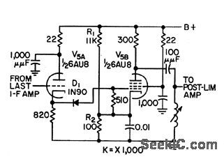
Used in visual receiver of microwave relay. Signal is fed through triode cathode follower and diode-coupled to grid of pentode. D1 cuts off on positive r-f swing above d-c bias set by R1 and R2, to prevent grid of V5B from going positive and provide clipping on negative swing.-T. G. Custin and J. Smith, Relay System Diplexes Audio and Color Video, Electronics, 31 :25, p 64-67. (View)
View full Circuit Diagram | Comments | Reading(739)
RADAR_NOISE_CLIPPER_LIMITER
Published:2009/7/15 23:21:00 Author:Jessie
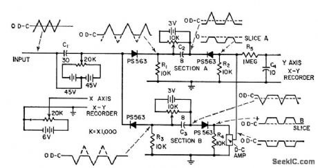
Used in plotting amplitude-distribution density of noise and vibration signals over range of 1 to 10,000 cps. Section A samples d-c biased input signal between zero and positive half of slice width. Section B similarly handles negative half. Output of B is inverted and biased in d-c amplifier to produce positive square wave. Recorder plots average of combined outputs from A and B sections.-D. J. Zoll, Simple Plotter Analyzes Radar Noise Rapidly, Electronics, 31:11, p 162-164. (View)
View full Circuit Diagram | Comments | Reading(779)
GEIGER_MUELLER_TUBE_CIRCUIT
Published:2009/7/14 2:21:00 Author:May
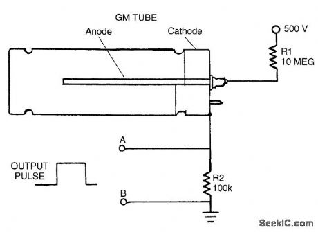
A GM tube is useful for detecting radioactivity. The tube is constructed with a cylindrical electrode (cathode) surrounding a center electrode (anode). The tube is evacuated and filled with a neon and halogen gas mixture. A voltage potential of 500 V is applied across the tube, through a 10-MΩ current-limiting resistor (R1). The detection of radiation relies upon its ability to ionize the gas in the GM tube. The tube has an extremely high resistance when it is not in the process of detecting radioactivity. When an atom of the gas is ionized by the passage of radiation, the free electron and positive ionized atom that are created move rapidly toward the two electrodes in the GM tube. In doing so, they collide with and ionize other gas atoms, which creates a small avalanche effect. This ionization drops the resistance of the tube, allowing a sudden surge of electric current that creates a voltage across the resistor R2, which can be seen as a pulse. (View)
View full Circuit Diagram | Comments | Reading(2831)
2_METER_FM_EXCITER
Published:2009/7/14 2:19:00 Author:May
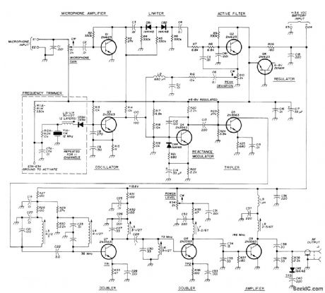
Includes both deviation and microphone gain controls. Low-pass filter following limiter eliminates raspy voice signal. Input takes either carbon or transistor-amplified dynamic microphones. Phase modulation used is suitable for multichannel operation and frequency synthesizers. Oscillator uses 12-MHz series-resonant crystals. Voltage regulator for oscillator, modulator, and audio stages minimizes effects of line-voltage variation and noise. Output power of 150-200 mW is enough to drive new TRW and Motorola RF power modules. Article gives construction and alignment details.-J. Vogt, High-Performance Two-Meter FM Exciter, Ham Radio, Aug. 1976, p 10-15. (View)
View full Circuit Diagram | Comments | Reading(1955)
OPTOISOLATOR_AS_SOLID_STATERELAY
Published:2009/7/14 2:09:00 Author:May
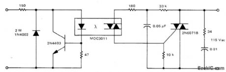

Circult provides input protection of LED from overvoltage and reverse polarity,along with snubber network for handling inductive AC loads. Triac should be chosen to handle load.Safe input voltage range is 3-30 VDC.-P.O'Neil, Applications of the MOC3011 Traic Driver, Motorla,Phoenix,AZ,1978,AN-780,p 6. (View)
View full Circuit Diagram | Comments | Reading(1201)
| Pages:159/471 At 20141142143144145146147148149150151152153154155156157158159160Under 20 |
Circuit Categories
power supply circuit
Amplifier Circuit
Basic Circuit
LED and Light Circuit
Sensor Circuit
Signal Processing
Electrical Equipment Circuit
Control Circuit
Remote Control Circuit
A/D-D/A Converter Circuit
Audio Circuit
Measuring and Test Circuit
Communication Circuit
Computer-Related Circuit
555 Circuit
Automotive Circuit
Repairing Circuit