
Circuit Diagram
Index 1404
HEADLIGHT_OFF_INDICATOR
Published:2009/6/19 2:37:00 Author:May
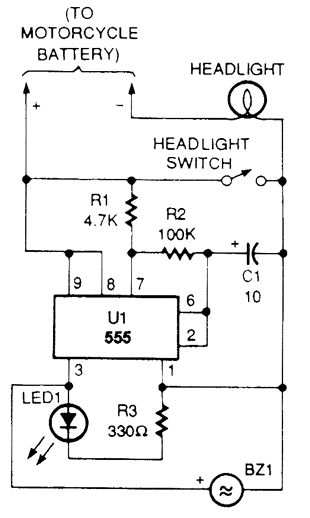
Increasing the value of R2 or C1 will lower the oscillator's frequency and decreasing one of those values will increase the frequency. The IC's output at pin 3 drives the LED through R3 and sends power to the piezo sounden Use a bright LED so that you will be able to see it in the daytime. (View)
View full Circuit Diagram | Comments | Reading(794)
MOTORCYOLE_HEADLIGHT_MONITOR
Published:2009/6/19 2:37:00 Author:May
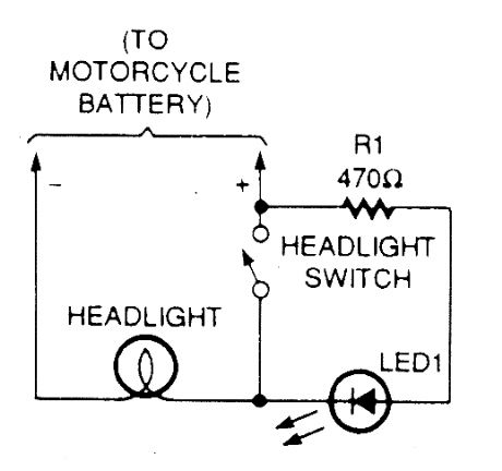
The headlight on most newer bikes is keyed on with the ignition switch to guarantee that you are never underway without your headlight be-ing on. However, many older bikes have a fac-tory headlight switch, and a growing number of the newer bikes are owner-modified in the same way.A simple headlight monitor circuit consists of just an LED and a current-limiting resistor wired across the headlight switch, as shown.When the ignition is on and the headlight switch is off, the LED will glow. (View)
View full Circuit Diagram | Comments | Reading(668)
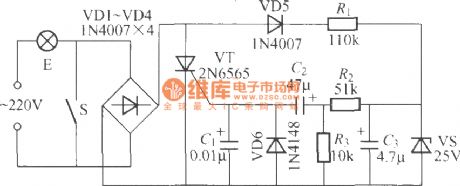
The subsonic remote control lamp switch circuit (1)
Published:2011/7/5 1:49:00 Author:zj | Keyword: The subsonic, remote control, lamp switch circuit
As shown, the remote control light uses 18kHz acoustic wave as remote control signal. The auditory range is from 20Hz to 20kHz. Ear inaudible ultrasonic is more than 20kHz. Although 18kHz wave is in audible sound wave range, it is in the audible sound wave end edge and is close to the lowest frequency. And human ear will not be sensitive. You can only hear the sound Ci Ci . So we call it The ultrasonic. (View)
View full Circuit Diagram | Comments | Reading(646)
SYNC_GATINC_CIRCUIT
Published:2009/6/19 2:36:00 Author:May
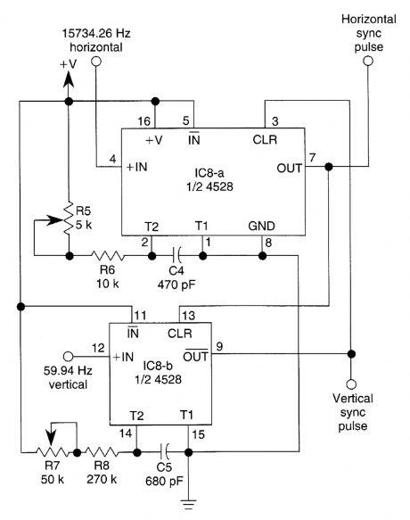
This circuit guarantees that only one type of sync pulse is generated at a time. During vertical sync periods, horizontal sync is disabled. (View)
View full Circuit Diagram | Comments | Reading(812)
CAR_AUDIO_POWER_SUPPLY
Published:2009/6/19 2:35:00 Author:May
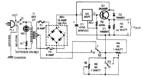
This supply has a variable output voltage feature and a dual voltage switch, S2. Q1 should be ad-equately heatsinked. (View)
View full Circuit Diagram | Comments | Reading(696)
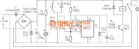
Delay light pull switch circuit (3)
Published:2011/7/5 1:52:00 Author:zj | Keyword: Delay light, pull switch circuit
View full Circuit Diagram | Comments | Reading(534)
ONE_OP_AMP_BANDPASS_FILTER
Published:2009/6/19 2:34:00 Author:May

View full Circuit Diagram | Comments | Reading(1)
Cycle timing lamp circuit
Published:2011/7/5 3:39:00 Author:zj | Keyword: Cycle timing, lamp circuit
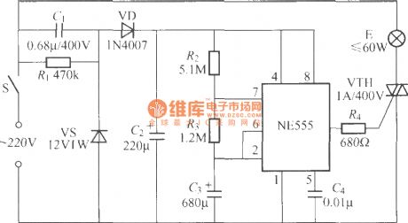
As the diagram shows it is a cycle timing lamp circuit. When the switch S is closed, the lamp will automatically light up for 50min and go out for 10min,and this process will go round and begin again and again. It can be used as reading and writing desktop lamp. It can force the student to relax for 10min after working for 50min. It is good for students' health. (View)
View full Circuit Diagram | Comments | Reading(684)
The main circuit block diagram of single phase conversion type UPS power supply
Published:2011/4/11 1:12:00 Author:may | Keyword: single phase conversion type, UPS power supply
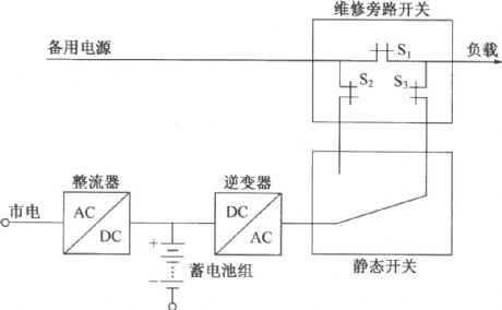
The main circuit block diagram of setting static switch single phase conversion type UPS power supply
UPS power supply can be divided into conversion type and parallel operation type according to compound mode of inverter. The main circuit block diagram of setting static switch single phase conversion type UPS power supply is shown in the diagram. From the diagram we can know that: when it’s in commercial power and normal work, adopt inverter as main power supply and energy supply to load. In order to let maintenance easy, it set a manual maintenance bypass switch, namely when maintaining, first let bypass switch S close, then let S2, S3 and static switch cut. The system changing to use back up supply to energy supply to load, then UPS system and bypass system separate, at this time can maintain to inverter, static switch. When adopting inverter as main power supply, first close static switch and bypass switch S2, S3, then cut S1. (View)
View full Circuit Diagram | Comments | Reading(2401)
Remote control type music color lamp circuit (2)
Published:2011/7/5 21:42:00 Author:zj | Keyword: Remote control type, music color lamp circuit
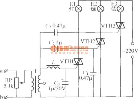
As shown in the diagram,the wire type music color lamp circuit candivide music signalinto high, medium and low three frequency bands, respectively drive the red, green, blue three colors lantern group with music flashing, can produce a riot of colours, colorful light. Available T transistor radio small input transformer ; inductance L homemade :use diameter of 1mm wire in a 25mmby 28mm insulating frame around the 200 windings. It will be fine. (View)
View full Circuit Diagram | Comments | Reading(839)
Remote control type music color lamp circuit (1)
Published:2011/7/5 21:49:00 Author:zj | Keyword: Remote control type, music, color lamp circuit

As shown in the figure it is a simple wire type music color lamp circuit. From the speaker at both ends of the audio frequency voltage through the wire connected to the A, B end, by the potentiometer RP partial pressure applied to the audio transformer T primary, audio voltage by T followed by a boost secondary to the bidirectional thyristor control VTH electrode and the second anode. When the audio frequency voltage is high, VTH opened, festoon lamp string E light; when the music stops or is weak enough to trigger the VTH, VTH in alternating current crosses zero is turned off. Therefore, the lamp string E brightness flickers with horn playing music rhythm. Regulating potentiometer RP value can modulate circuit wire sensitivity; T canadoptsmall input transformer in transistor radio. (View)
View full Circuit Diagram | Comments | Reading(774)
Five flash lamp string circuit (1)(M1500P)
Published:2011/7/5 22:08:00 Author:zj | Keyword: Five flash, lamp string circuit
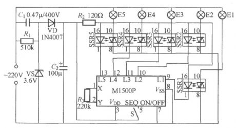
As shown in the figure itis five flash lamp string controller made by M1500P five flash integrated circuit produced by ShenzhenSkywave semiconductor limited Company. M1500P uses the CMOS process, it uses the power supply voltage standard values for 3V, L1 ~ L5 five output end can be directly driven LED blinking, flashing mode there are random and continuous two options are available. SSR1 to SSR5 uses TAC081 IC type solid state relay. Its maximum load currentis 1A. (View)
View full Circuit Diagram | Comments | Reading(675)
Four path lights with bird control circuit using BH9201
Published:2011/7/5 22:46:00 Author:zj | Keyword: Four path lights, bird twitter control circuit
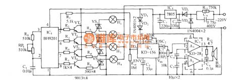
The circuit is shown above. It is composed of a lamp control circuit of SCR trigger control circuit, a sounding circuit, audio power amplifier circuit of birdsong and AC voltage reducing rectifier circuit. It can in the four path lights string strobe at the same time, a beautiful melodious birds toot cries. BH9201 is a special lantern control integrated circuit, it has four control signal output regulator connected in an external pins 2, 3 of RP1, can make the four path lights show jumping, running water, the light, the three state. R0, RP1, C1 inside the BH9201 oscillation circuit of an external resistor and capacitor. (View)
View full Circuit Diagram | Comments | Reading(773)
Practical delay lamp circuit (3)
Published:2011/7/6 20:58:00 Author:zj | Keyword: Practical, delay lamp
As the diagram shows, it is a delay light controllor with good performance. The connection betweenthe controller and the lamp is two wire type. The installation and the using is very convenient. And there is no special requirement for components. (View)
View full Circuit Diagram | Comments | Reading(716)
Practical delay lamp circuit (2)
Published:2011/7/6 21:02:00 Author:zj | Keyword: Practical, delay lamp circuit
View full Circuit Diagram | Comments | Reading(627)
AC 110V-DC 12V/8A switching power supply
Published:2011/4/23 3:59:00 Author:May | Keyword: AC 110V-DC 12V/8A, switching power supply
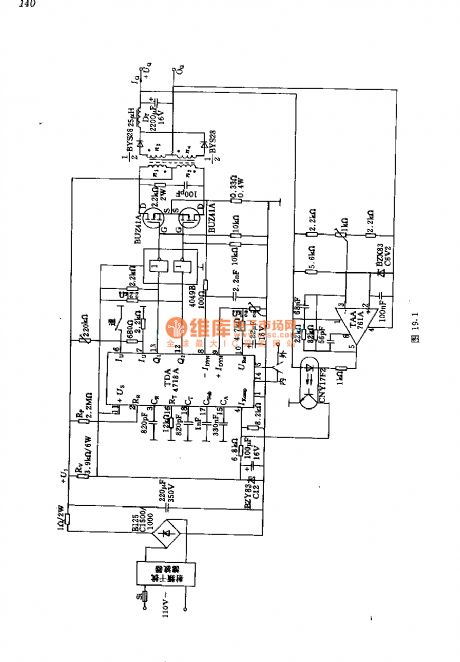
In this circuit, it generates about 150V DC voltage after the AC voltage passing bridge rectifying and capacitor filtering. It is chopped by two power MOS transistor BUZ41A with 50kHz. Then it changes to 18V AC voltage by transistor. Finally, it is full wave rectifying and filtering to output 12V DC voltage. Integrated circuit TDA4718 in the circuit can generate 100kHz high frequency oscillation. It can limit the voltage drop on total power supply resistor by utilizing its current limiting circuit. The output of integrated circuit TDA4718 can drive power transistor by CMOS six-inverter 4049.
Transformer data: n1=n2=67 turns, 30×0.1mm copper lacquered wire (double) ;
n3=n4=9 turns, 2×60×0.1mm copper lacquered wire (double) .
Choke data: 10 turns, 4×30×0.1mm copper lacquered wire. (View)
View full Circuit Diagram | Comments | Reading(3258)
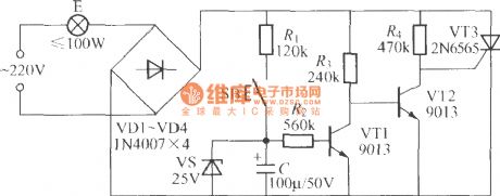
Practical delay lamp circuit (1)
Published:2011/7/6 21:13:00 Author:zj | Keyword: Practical, delay lamp circuit
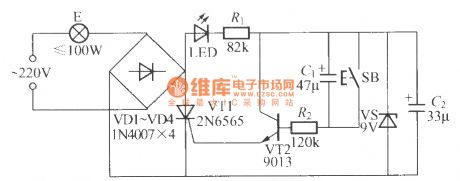
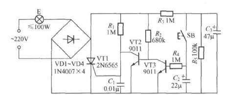
As the diagram shows it is a practical delay light controllor suitable for staircase aisle or toilet. When you press the switch SB down, it will light up for a few minutes. Then after that it will go out. (View)
View full Circuit Diagram | Comments | Reading(666)
Delay lamp circuit using relay (3)
Published:2011/7/6 22:50:00 Author:zj | Keyword: Delay lamp circuit, using relay
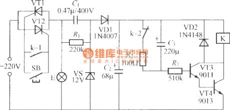
As shown in the figue, VT1, VT2 can adopt two 1A / 400V type unidirectional thyristors with the same properties. K can use JRX-13F, DC12V type miniature electromagnetic relay, which has two sets of switch contacts, and can meet the requirements. (View)
View full Circuit Diagram | Comments | Reading(649)
Delay lamp circuit using relay (2)
Published:2011/7/7 2:02:00 Author:zj | Keyword: Delay lamp circuit, using relay
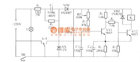
As the figue shows, it is a delay lamp circuit using relay with good perfomance. Press down SB to makelamp E light. At the same time,the 220V AC passes capacitance step-down half-wave rectifying and voltage-stabilizing circuit composed of VS, VD1,C1,C2.The C2 ends outputvoltage is 12V. Three transistor VT1 base is relay contact k-1 grounding and stop, so VT2 conductive, electric relay K. Contact k-1 backward often start, the key SB short circuit self-locking, so the release SB, light E can still be energized to emit light. The positive power supply by RP, R3 to C3 the VT1 capacitor charging base potential gradually raised, when raised to a certain degree, the VT1 conduction, VT2 VT1, VT2 cutoff, which consists of the Schmidt circuit turned back to the original state, the relay K release, contact k-1 reset lamp E power supply circuit is cut off and the lights went out. (View)
View full Circuit Diagram | Comments | Reading(1138)
SAW_FILTER_IMPEDANCE_MATCHING
Published:2009/6/19 2:34:00 Author:May
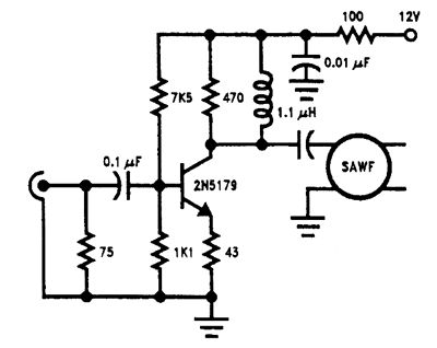
This circuit matches a saw ffiter to an IF amplifier. (View)
View full Circuit Diagram | Comments | Reading(1029)
| Pages:1404/2234 At 2014011402140314041405140614071408140914101411141214131414141514161417141814191420Under 20 |
Circuit Categories
power supply circuit
Amplifier Circuit
Basic Circuit
LED and Light Circuit
Sensor Circuit
Signal Processing
Electrical Equipment Circuit
Control Circuit
Remote Control Circuit
A/D-D/A Converter Circuit
Audio Circuit
Measuring and Test Circuit
Communication Circuit
Computer-Related Circuit
555 Circuit
Automotive Circuit
Repairing Circuit