
Circuit Diagram
Index 1409
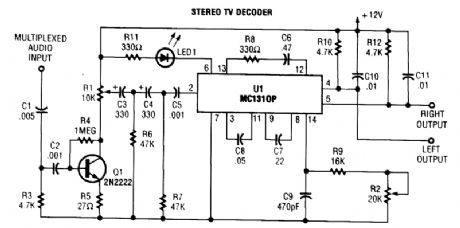
STEREO_BALANCE_METER
Published:2009/6/19 1:54:00 Author:May
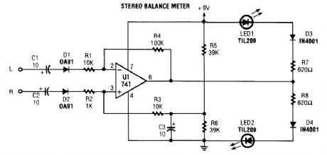
When L & R signals are equal, no output is present frorrt U1, and pin 6 is at a steady 4.5 V. Un-balanced audio causes the LEDs to vary in brightness, which causes a difference that corresponds to unbalance between channels. (View)
View full Circuit Diagram | Comments | Reading(0)
80_WATT_IC_AUDIO_AMPLIFIER
Published:2009/6/19 1:54:00 Author:May
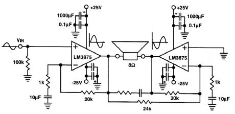
This audio power amp will deliver 80W of audio into an 8-Ω load The LM3875 IC devices shouldbe suitably heatsinked。Note that the amplifier IS a bridged circuit,with both speaker leads“hot.” (View)
View full Circuit Diagram | Comments | Reading(2038)
ACTIVE_BANDPASS_FILTER_CIRCUIT
Published:2009/6/19 1:52:00 Author:May
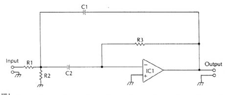
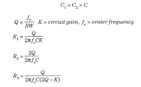
In this circuit, (View)
View full Circuit Diagram | Comments | Reading(729)
MINI_STEREO_AMPLIFIER
Published:2009/6/19 1:52:00 Author:May
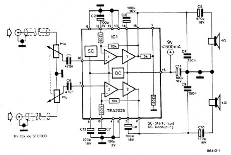
Using a Thomson TEA2025, this stereo amplifier provides 1 W per channel into 4 Ω with a 9-V supply. Input sensitivity is 25 mV p-p for full output. Note that pins 4, 5, 12, and 13 of IC1 should be effectively grounded to a ground plane and heatsinked. (View)
View full Circuit Diagram | Comments | Reading(1193)
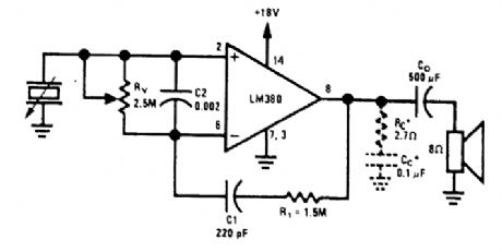
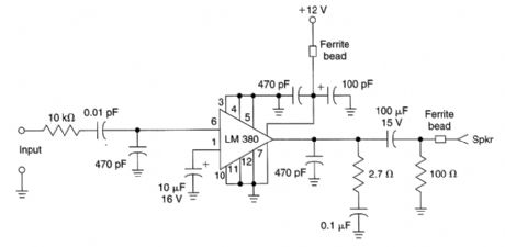
PHONO_AMP
Published:2009/6/19 1:51:00 Author:May
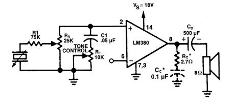
The figure shows the LM380 with a voltage-divider volume control and high-frequency roll-off tone control. (View)
View full Circuit Diagram | Comments | Reading(838)
BASIC_QUASI_COMPLEMENTARY_POWER_AMPLIFIER_CIRCUIT
Published:2009/6/19 1:51:00 Author:May
View full Circuit Diagram | Comments | Reading(925)
SALLEN_KEY_HIGH_PASS_FILTER
Published:2009/6/19 1:50:00 Author:May
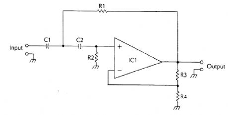

R3 and R4 set the circuit galn (View)
View full Circuit Diagram | Comments | Reading(805)
AUDIO_EXPANDER
Published:2009/6/19 1:50:00 Author:May
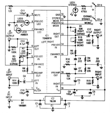
This audio processor is based on the Signetics/Philips TDA3810N stereo, spatial, pseudo-stereo processor, IC. This processor uses a Philips TDA3810IC device, and it functions as an expander, pseudo stereo processor, and audio enhancer. Pseudo stereo is obtained by routing various frequencies to each channel via active filters (View)
View full Circuit Diagram | Comments | Reading(6908)
STAET_VARIABLE_FILTER
Published:2009/6/19 1:49:00 Author:May
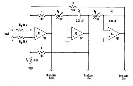
The state variable filter shown consists of only three op amps and a few passive components. It provides several key features. These include the ability to simultaneously provide low-pass, high-pass, and bandpass filter functions, and adjust bandwidth in a wide range by changing the values of Cf and Rf. The device also is easy to tune and simple to congtruct, while the quality factor (Q) of each filter is independent of each other. (View)
View full Circuit Diagram | Comments | Reading(1012)
RIAA_PHONO_AMPLIFIER
Published:2009/6/19 1:48:00 Author:May
View full Circuit Diagram | Comments | Reading(670)
ONE_CHIP_STEREO_PREAMP_WITH_TONE_CONTROL
Published:2009/6/19 1:48:00 Author:May

A Motorola TCA5500 or TCA5550 can provide a stereo preamplifier system with tone controls. This circuit provides a gain of about 10X, a 14-dB tone-control range, a 75-dB volume control range, and it can operate from 8 to 18 Vdc. IC2 provides 15 V for 101, and the input of IC2 can be supplied from the power amplifier's power supply (+) rail. D1 and R5 should be used if over 30 V input will be used. (View)
View full Circuit Diagram | Comments | Reading(4063)
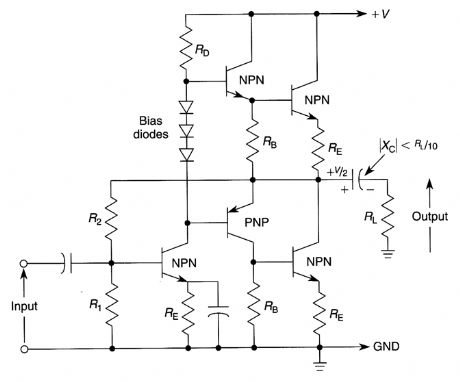
BASIC_QUASI_COMPLEMENTARY_POWER_AMPLIFIER_WITH_SPLIT_POWER_SUPPLIES
Published:2009/6/19 1:47:00 Author:May
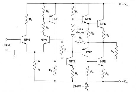
This is the basic circuit used in many audio power output stages where split supplies are used.This amplifier is inherently dc coupled and has high open loop gain and good dc stability if the feedback network is properly designed. (View)
View full Circuit Diagram | Comments | Reading(1215)
EXPERIMENTAL_FIBER_OPTIC_DATA_RECEIVER
Published:2009/6/19 1:47:00 Author:May
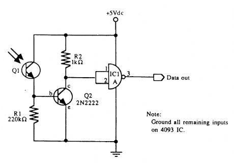
An infrared phototransistor acts as the sensor for this recelver IC1a is a section of a CD4093 CMOS NAND gate. (View)
View full Circuit Diagram | Comments | Reading(1748)
RFI_PROOF_AUDIO_POWER_AMPLIFIER
Published:2009/6/19 1:46:00 Author:May
This 1-watt audio amplifier was used in an FM repeater and proved to be immune to strong RE signal pickup. It functioned well in very strong RE fields. (View)
View full Circuit Diagram | Comments | Reading(742)
STRAIN_GAGE_SENSOR
Published:2009/6/19 1:46:00 Author:May
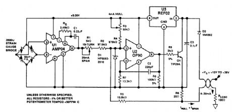
In this loop-powered strain-gage sensor application, a 50-mV full-scale(FS)bridge output is amplified and calibrated for a 4-20-mA transmitter output. Power is fumished by the remote loop sup-ply of 12 to 36 V. (View)
View full Circuit Diagram | Comments | Reading(3167)
EXPERIMENTAL_DATA_TRANSMITTER_FOR_FIBER_OPTICS
Published:2009/6/19 1:45:00 Author:May
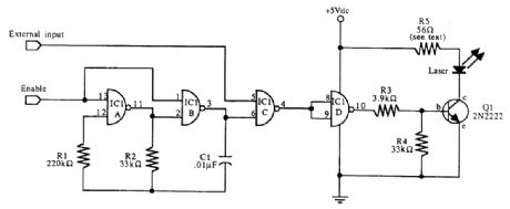
This schematic for an experimental data transmitter uses optical fibers and a laser diode. Trans-mission frequency of the free-running oscillator is approximately 3 kHz. R5 might have to be varied to suit your laser diode. IC1 is a CD4093. (View)
View full Circuit Diagram | Comments | Reading(2321)
16_W_BRIDGE_AMPLIFIER
Published:2009/6/19 1:45:00 Author:May

This circuit delivers 16 W RMS audio into a 4-Ωload (RL). The ICs are LM383s. (View)
View full Circuit Diagram | Comments | Reading(740)
SIMPLE_LOCK
Published:2009/6/19 1:44:00 Author:May
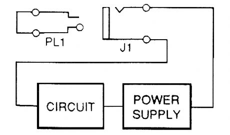
Only an appropriately wired plug of the right size will activate circuits with a nonshorting jack in their power supply circuit. (View)
View full Circuit Diagram | Comments | Reading(793)
POWER_SUPPLY_FOR_VACUUM_TUBE_AMPLIFIER
Published:2009/6/19 1:43:00 Author:May
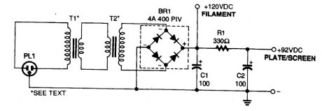
The power supply for the amplifier uses two low-voltage transformers connected back-to-back The full-wave bridge rectifier, BR1 provides dc for the filaments, plates, and screens. (View)
View full Circuit Diagram | Comments | Reading(967)
SIMPLE_VACUUM_TUBE_AMPLIFIER
Published:2009/6/19 1:43:00 Author:May
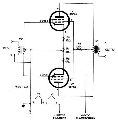
Using a pair of 60 FX5 tubes, direct operation from 120 Vac is possible. However, the use of a power supply with an isolation transformer is recommended. RI is adjusted for equal voltages at pin 1 of V1 and V2. The power output is about 2 to 3 watts. (View)
View full Circuit Diagram | Comments | Reading(1718)
| Pages:1409/2234 At 2014011402140314041405140614071408140914101411141214131414141514161417141814191420Under 20 |
Circuit Categories
power supply circuit
Amplifier Circuit
Basic Circuit
LED and Light Circuit
Sensor Circuit
Signal Processing
Electrical Equipment Circuit
Control Circuit
Remote Control Circuit
A/D-D/A Converter Circuit
Audio Circuit
Measuring and Test Circuit
Communication Circuit
Computer-Related Circuit
555 Circuit
Automotive Circuit
Repairing Circuit